Project - 2 - Meshing on the suspension Assembly
MESHING ON THE SUSPENSIONS ASSEMBLY
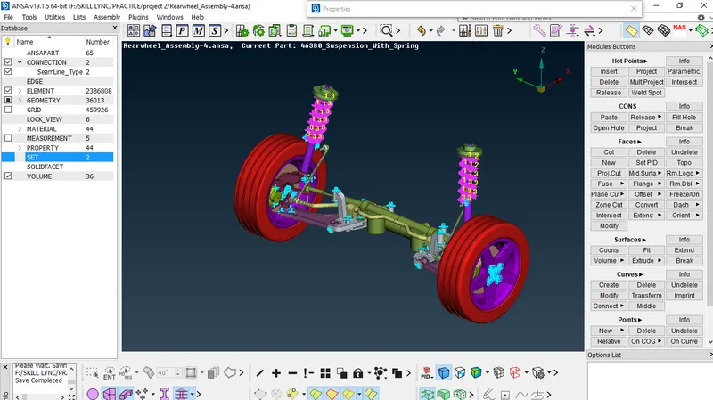
AIM: Meshing on the given suspension assembly according to the given quality criteria and mesh parameters. Use Appropriate connections to connect the suspension assembly and perform a Symmetry commands to reflect the half-finished model to the other side.
PROCEDURE:
STEP 1:
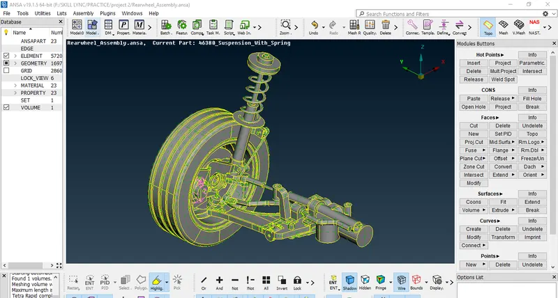
Import the suspension model to ANSA. The file has to be .ansa or.IGS file to import to ANSA software.
STEP 2:
The suspension model which we have consist of three PIDs
- TYRE.
- RIM.
- SUSPENSION SYSTEM.
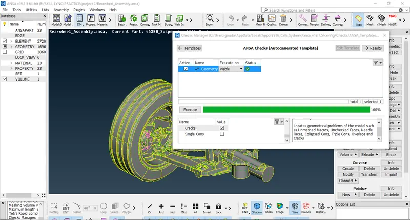
As per the given first, we need to check the geometry of the model by using the CHECK< geometry option in the TOOLS command.
We need to fix the geometrical errors if there are any.
STEP 3:
After the geometry cleanup, we need to set new PIDs for the model. In the given suspension assembly model we are already given 3 PIDs as I mentioned before.
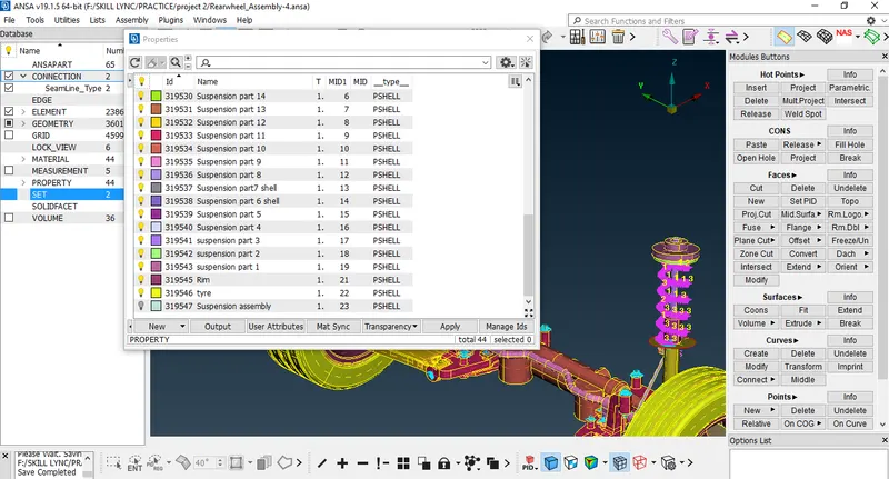
The Tyer and Rim are already given separate PIDs but the suspension part of the model has been given as a single PID so, we now have to use the PID region option and assign new PIDs for each part in the suspension.
we can see the new PIDs in the Properties option in the LIST command.
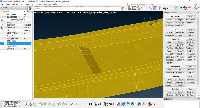
After the new PIDS is created we have to do some topological cleanup by using the CUT option and creating new faces by using the NEW option in the FACES command in the TOPO module on the model.
STEP 4:
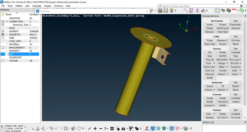
For some parts in the model which as a thickness below 5mm and have uniform thickness we have to get the MID SURFACE in order to mesh them. so to get mid surface use the OFFSET option in FACES which is in the TOPO module.
STEP 5:
As the PIDs for each part are given. Now we have to apply quality criteria and mesh parameters and model the suspension Assembly accordingly.
For assigning the quality criteria and mesh parameters for any model we have to go to the UTILITY command in which we can find the quality criteria and mesh parameters options.
Quality criteria as given in the question is attached below
|
S.No |
Quality Criteria |
Value |
|
1 |
Target/Average length |
6.5 |
|
2 |
Minimum Length |
5 |
|
3 |
Maximum Length |
10 |
|
4 |
Skewness |
45 |
- Quality criteria for Surface Meshing of Non Uniform thickness components other than Tyre and Rim (Element type: Tria) :
|
S.No |
Quality Criteria |
Value |
|
1 |
Target/Average length |
4 |
|
2 |
Minimum Length |
2 |
|
3 |
Maximum Length |
6 |
|
4 |
Skewness |
45 |
- Quality Criteria for Volume meshing of all Non Uniform thickness components (Element type: Tetra Elements):
|
S.No |
Quality Criteria |
Value |
|
1 |
Tet-collapse |
0.2 |
- Quality criteria for Mid surfacing of Uniform thickness part which has a thickness less than 5 mm (Element type: Mixed elements) :
|
S.No |
Quality Criteria |
Value |
|
1 |
Target/Average length |
4 |
|
2 |
Minimum Length |
2 |
|
3 |
Maximum Length |
6 |
|
4 |
Aspect |
3 |
|
5 |
Warpage |
15 |
|
6 |
Skewness |
45 |
|
7 |
Jacobian |
0.7 |
|
8 |
Minimum Quad Angle |
45 |
|
9 |
Maximum Quad Angle |
135 |
|
10 |
Minimum Tria Angle |
30 |
|
11 |
Maximum Tria Angle |
120 |
STEP 6:
First, apply the quality given to the tire and rim then by using the spot meshing option in the mesh generation which is in the mesh modules mesh the tire and rim. select the mesh type as TRIA.
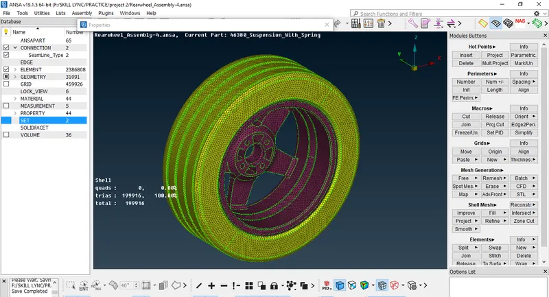
Use RECONSTRUCT option in SHELL MESH which is in MESH MODULE to improve the mesh quality and get rid of OFF ELEMENTS.
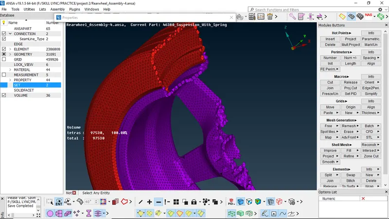
After completing the meshing on the tire and rim we have to do the volume mesh on them. for that we have to go to the VOLUME MESH module.
Fro working on Volume meshing on any part of the model first we have to define the volume to the part. To define we have to use the DEFINE option in VOLUMES which is in the VOLUME MESH module.
After the volume is defined.By using TETRA ELEMENTS in UNSTRUCTURED MESH which is in volume mesh module mesh the defined parts.
Repeat the same process for the Non Uniform thickness components other than Tyre and Rim by appling the given quality .
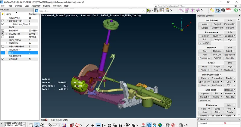
For the uniform thickness part which has a thickness of less than 5 mm we have to first obtain the mid by using offset after that the set the given quality criteria and mesh parameters and then set the element type to mixed in mesh parameters. After all, this meshes the mid surface by using the spot mesh option. and improve the mesh by using reconstruct option and get rid of off elements.
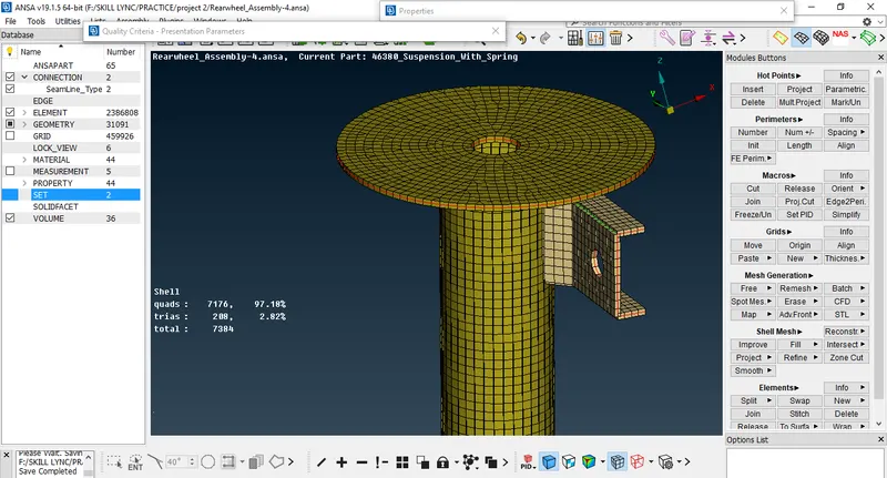
STEP 7:
After the meshing on the suspension model is done we have to connect the parts by using CONNECTIONS by NASTRAN in DECKS MODULE.
Most of the connections in the model are RBE2 connections which can be done by using the RBE2 option in ELEMENTs which is in DECKS MODULE. To perform RBE2 connections click on RBE2 and select the nodes in the place where u want to create the connection and then confirm it and the connection will be created. nodes can be selected in many ways by using NODES OR ENT options in the FEATURE SELECTION OPTION.
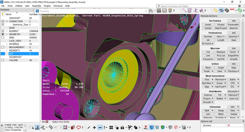
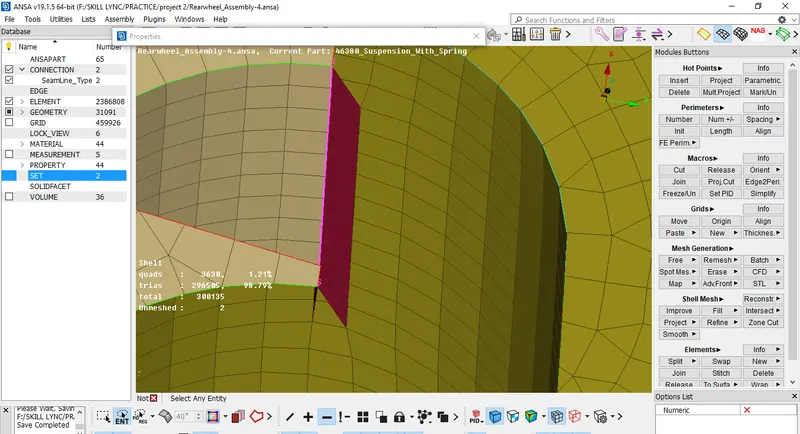
We also have some parts in which we have to perform the SEAM WELD CONNECTIONS. So to perform seam welding connections we have to first create a curve using the CONS.For creating curves by using cons we have to use the CONStoCURVES option in CURVES which is in the TOPO module.
Then the curve should be converted to SEAM LINE by using the CONVERT option in ASSEMBLY OPTION.(Assembly<convert<curve
After the SEAM LINE is created we have to go to ASSEMBLY<CONNECTIONS<(select the seam line created )<(select the two parts and assign them SHIFT+? when the seam connections need to be created)<(select OVERLAP SHELL to give the different info like distance, width and assign different PID.)
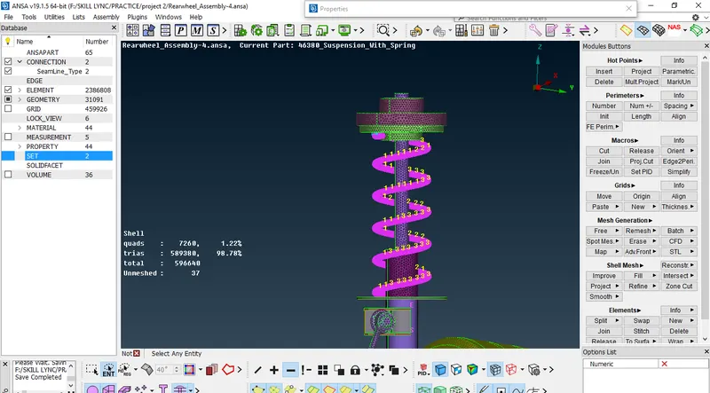
In the suspension assembly,we have a spring in which a PBAR connection needs to be created. So for creating the CBAR CONNECTION we have to first create a curve by using the CURVE MIDDLE option in CURVES in TOPO MODULE. and connect it by using CONNECT option.
After the curve is created we have to create the CBAR CONNECTION by using CBAR option in ELEMENTs which is in NASTRAN DECKS. NASTRAN DECKS<ELEMENTS<CBAR
STEP 8:
After all the meshing and connections are completed on the model we have to now REFLECT the model by using the SYMMETRY command to finish the model to the other side.
To perform symmetry first go to UTILITIES< TRANSFORM<COPY(entities)<SYMMETRY<(give 3 coordinates) and press finish to get the reflection of the model on another side.
LEARNING OUTCOMES:
- Learned how to import the model to ansa.
- Learned how to do geometry check by using the check geometry option in tools.
- Learned how to give new PIDs.
- Learned how to do the topological cleanup by using options like cut and new in faces.
- Learned how to apply quality criteria and mesh parameters to any model.
- Learned how to do meshing both mixed and tria by using spot mesh in mesh module.
- Learned how to improve the mesh by using reconstruct and smooth options in the mesh module.
- Learned how to do volume meshing by using tetra elements.
- Learned how to define a volume to any part in any model.
- Learned how to do mid-surfacing by using offset
- Learned how to assign thickness to the mid-surface.
- Learned how to do connections like RBE2 and seam weld connections.
- Learned how to do PBAR connection.
- Learned how to reflect the model by using the symmetry option.
CONCLUSION:
Finally, Meshing on the given suspension assembly according to the given quality criteria and mesh parameters. Use Appropriate connections to connect the suspension assembly and perform the Symmetry command to reflect the half-finished model to the other side is done.
Attachments:
A zip file containing the worked model is attached.