Introduction to FEA
1. What do you understand by FEA?
FEA stands for Finite element analysis which is a commonly used method for multiphysics problems. It can also be defined as a numerical process that provides solutions to problems that would be difficult to obtain. It uses software-based numerical methods to analyze and understand the practical behavior of parts that are subjected to any kind of internal or external load.
2. What are other similar techniques available & how are they different?
Similar techniques to solve engineering problems close to finite element analysis are 'Real-time solution', and; Analytical solution'. Both these are very different from FEA. The real-time solution technique is used to find a solution for any engineering problem that uses real-time data such as external forces practically applied on beams etc. This method is very time-consuming and expensive. The other method ' Analytical solution' solves the problem using an engineering formula that resembles the problem. Comparing FEA to these methods, FEA has better overall accuracy and is less time-consuming, and also involves less cost.
3. What do you mean by linear & nonlinear analysis?
Liner analysis- Linear analysis is a case where the load-Displacement response is linear. There is a Linear relationship between the applied forces and the response to the system. It is also known as a linear static analysis because the load does not change w.r.t time or load applied is constant and also there are no net forces or moments acting on a body.
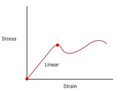
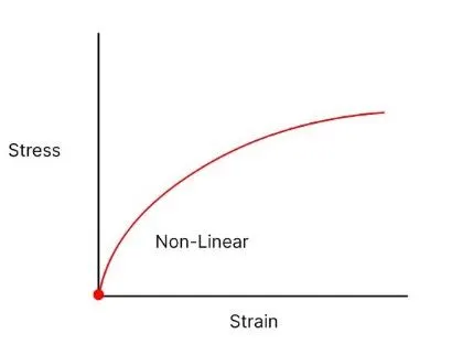
Non-linear analysis- A non-linear analysis is an analysis where a non-linear relation is between applied forces and displacements. The non-linear analysis is performed when stress and strain values are outside yield point. So for example it is basically performed on non-metals such as rubber or plastic as they do not have a relationship between stress and strain. It is a dynamic-based analysis.
4. Where is the nonlinear analysis needed?
The nonlinear analysis becomes necessary when the stiffness of the part changes under its operating conditions. The non-linear analysis is preferred when large deformations occur in a model due to dynamic loads and is also preferred when there is contact between the parts.
5. What is the existing type of nonlinearity?
The types of non-linearities are:
- Geometric nonlinearities: - They involve non-linearities in kinematic quantities such as strain-displacement relations in solids. such things can occur due to large displacements, large strains, large rotations, and so on.
- Contact Non-linearities:- These can also be classified as geometric nonlinearity because the area of contact is a function of deformation. So they occur due to the translation or rotation.
- Material Nonlinearities:- These occur when the stress-strain or force-displacement law is not linear, or when material properties change with applied loads.
6. What are Node and Elements?
NODE- A node is a coordinate location in space where the degrees of freedom are defined. The results of a finite element analysis such as deflections and stresses are usually at the nodes. These are the points where p[roperties are to be determined for an element.
ELEMENT- The entities joining nodes and forming a specific shape such as bar, triangle or quads is known as finite elelment. Every element has one or more nodes. The elements are connected to each other at the nodes only. The more the number of elements, the more accurate results can be obtained.
7. What type of elements are available in Hypermesh & application of the different type of elements?
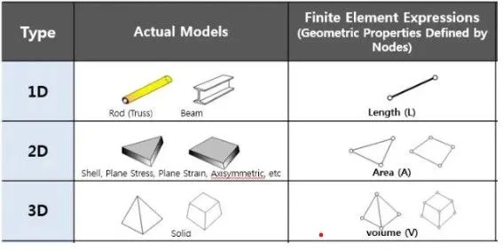
The different types of elements available in Hypermesh are 1D,2D, and 3D elements and special elements.
- 1D elements are used for modeling line-type members such as columns, beams, etc
- 2D elements are commonly used for plate-type members such as walls, slabs shells, etc
- 3D elements are used for structure with complex geometry which cannot be simplified for analysis.
- Special elements are used to apply boundary conditions to specify a gap between two pieces of geometry.
8. What do you understand by 1d element & what are its special engineering applications of it?
When configurations of elements are expressed in terms of one coordinate only, then the element is termed as a 1D element or line element.
1D elements have less number of nodes in the geometry compared to 2D and 3D elements. Each node has six degrees of freedom and hence 1D elements have fewer degrees of freedom compared to other elements. This results in the smallest stiffness matrix which in turn results in the smallest computational time.
9. How do you discretize a model?
Discretization is the process through which we can transform continuous variables, models, or functions into a discrete form. In the process of discretization, we take the original geometry and divide it into individual elements or volumes. Then the analysis is carried out for each of these elements.
10. How do you decide on element size & density?
In order to establish suitable finite element size:
- Perform chosen analysis for several different mesh sizes.
- Notice where high deformations or high stresses occur, perhaps it is worth refining mesh in those regions.
- Collect data from the analysis of each mesh: outcome, number of nodes in the model, computing time
Mesh density is the number of elements per unit area in a mesh. Higher density meshes usually produce more accurate analysis results, but take longer to analyze.
11. What do u mean by stress concentration & how will you mesh for such regions?
The stress concentration in a body happens because of sudden changes in the geometry of the body due to cracks, sharp corners, holes, decrease in the cross-section area. Due to these irregularities, there is an increase in the intensity of stress in the body. To mesh the stress concentrated areas, we can reduce the factors that cause the stress concentrations, such as fillet the sharp corners, etc. or we can choose a finer mesh density for stress concentrated regions.
12. What are 2D shell elements?
A 2D shell is a one-dimensional element that has a constant thickness and represents a shell. 2D shell elements are linear but can be curved or straight, much as a beam element would be in a 3D model. Basically, shell elements are used to model structures in which one dimension, the thickness, is significantly smaller than the other dimensions.
13. What are 3D elements?
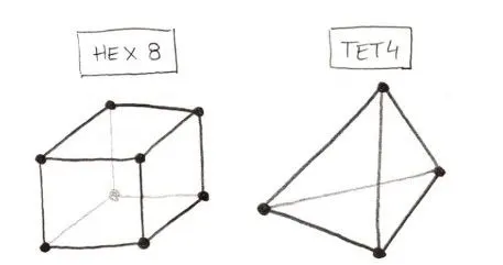
3D elements are usually used to mesh the volume of the part. They are derived from 2D elements and are used when the problem is unable to be simplified. A 3D solid element can be a tetrahedron or hexahedron in shape with either flat or curved surfaces.
14. What is the difference between BAR, ROD, and Beam?
Rod/Bar - The rods or bar is any member which is subjected to axial loads only. But rods are definitely circular cross-section whereas bars may or may not have a circular cross-section.
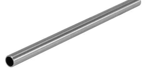
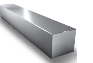
CIRCULAR BEAM SQUARE BEAM
A long structural member, mostly in a horizontal position, is supported on one (fixed) or more supports and a load is placed on it at one or more points then the member is called a beam. It could be any cross-section including circular, square, or anything. However, a specific cross section that has more material at the top and bottom gives better strength-to-weight ratio. Hence most common beam is an I beam.
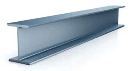
I BEAM