Week 6 - Creating connection for Rear door
OBJECTIVE:
- To give different types of connections for the rear door model of the car.
- These connections are given to the model using ANSA in the NASTRAN deck which will be used later for NVH simulation.
METHODOLOGY
- Import the meshed model
- Assign the property ID (PID) for different regions
- Identify different mechanisms and assign various connections for the rear door model.
PROCEDURE:
Step 1: Import the model. Before assigning connections for the model once observe the real car model as it gives an idea of the different types of connections used for various mechanisms.
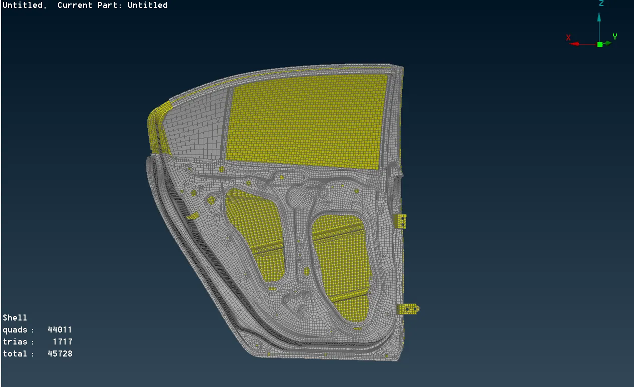
Step 2: Assign different PIDs for Glass and the parts which are needed to be welded.
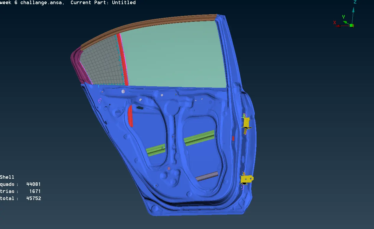
Step 3: In this challenge, we use different kinds of connections. The various connections are as follows:
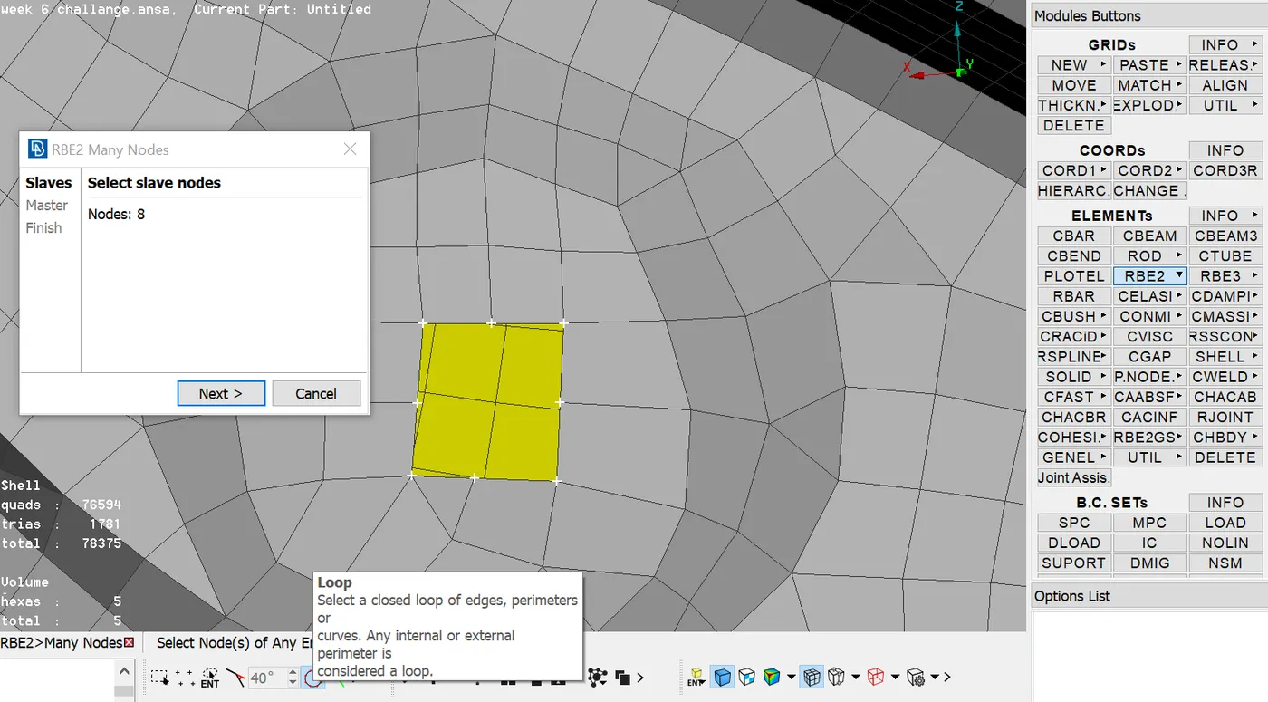
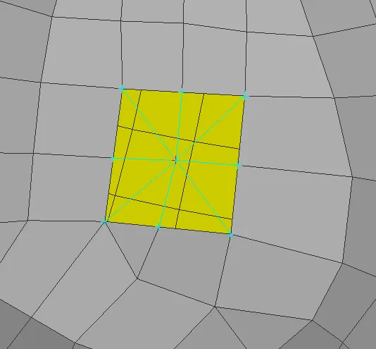
- RB2 Rigid is simply used to rigidize the hole. This type of connection is used where there are no bolts or washer elements. Use Elements --> RB2 --> Many nodes for connection, we can select all the nodes using loop selection. After selecting all the slave nodes a master node will be formed which connects all the slave nodes.
- Zone cut: It is used when an area must be rigidized at a particular region. This region acts as a washer element during simulation. Therefore, this type of connection is used where bolts exist. One must click on the edge of the circle using loop selection then the whole circle will be selected. Then specify the offset value. Now some areas will be reconstructed using the existing mesh parameters in order to form a zone cuts.
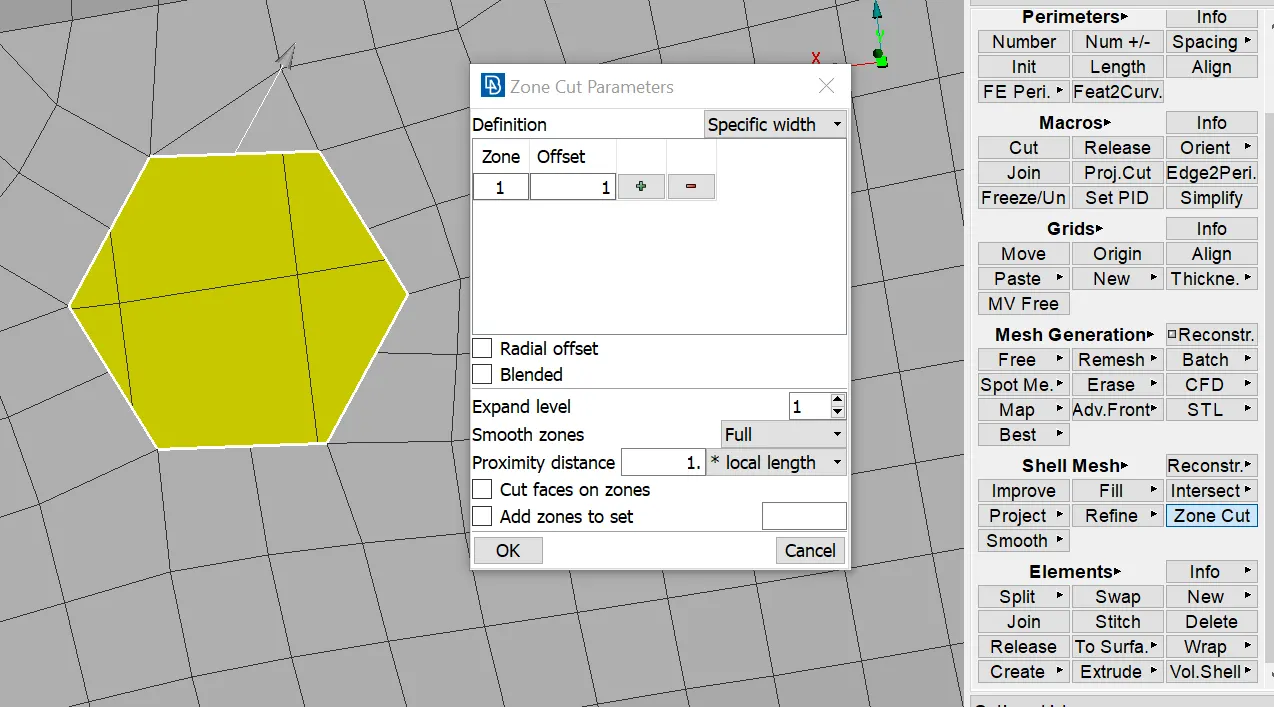
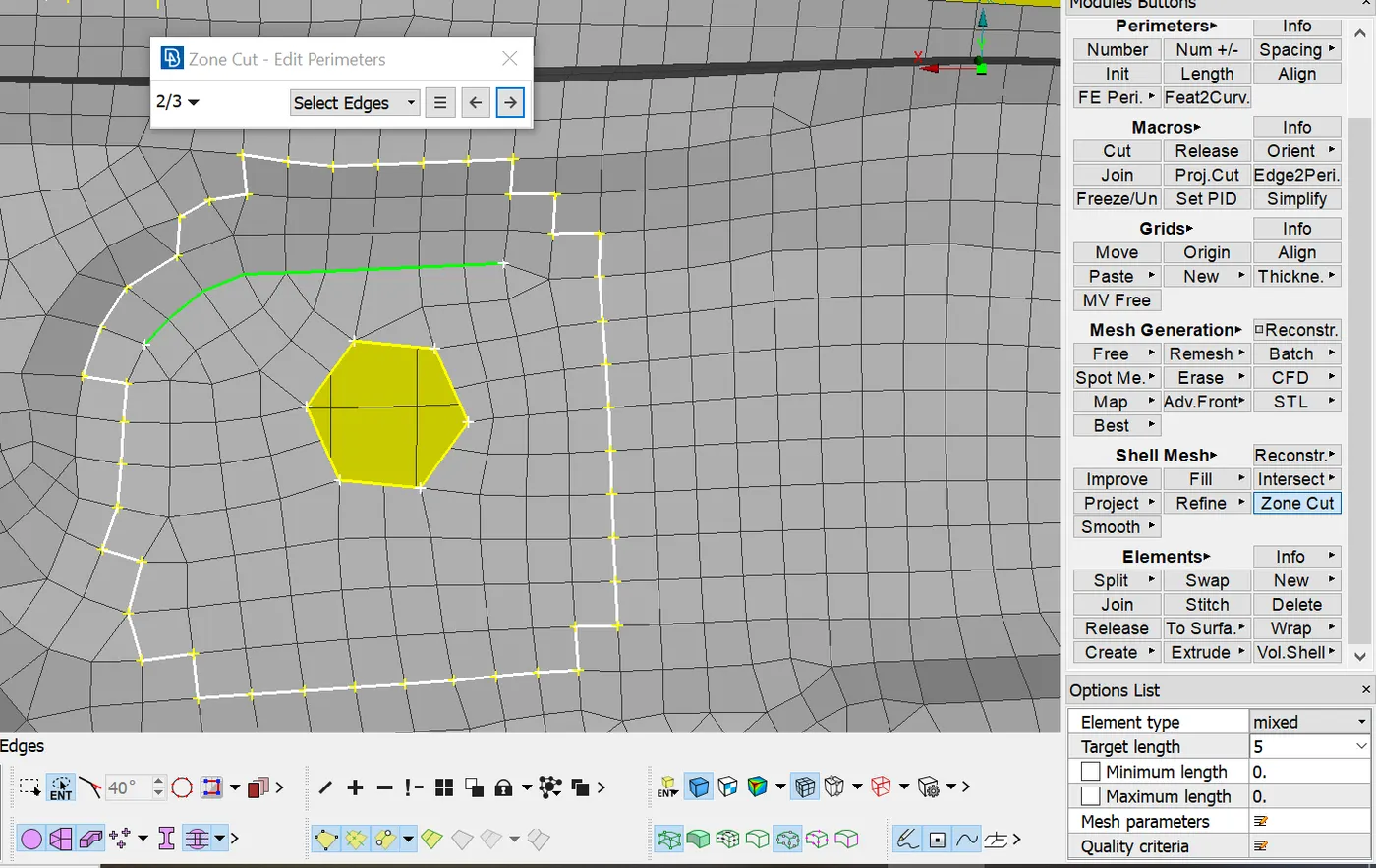
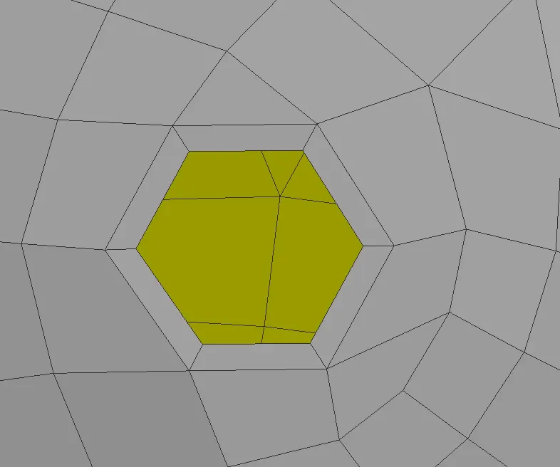
- Now use Elements RB2 for many nodes, and select the region using polyline selection in order to select all the slave nodes easily. Then RB2 connection is deployed along with the Zone cut.
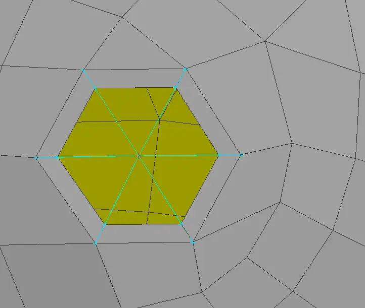
- Cluster or Spider RB2: This connection is used when a manual bolt connection must be deployed between two or more surfaces.
- For automatic bolt connection, one must follow these steps, Create COG for the hole --> COG is basically a 3D point, convert this 3D point to bolt --> Now open connections manager and select the bolt symbol which has created in the earlier step --> Then assign P1, P2, P3 --> Select FE type as Bolt and give the required values and constraints --> apply and then realize the connection.
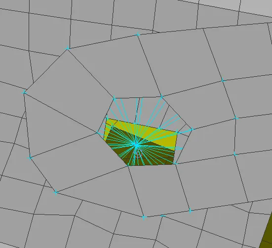
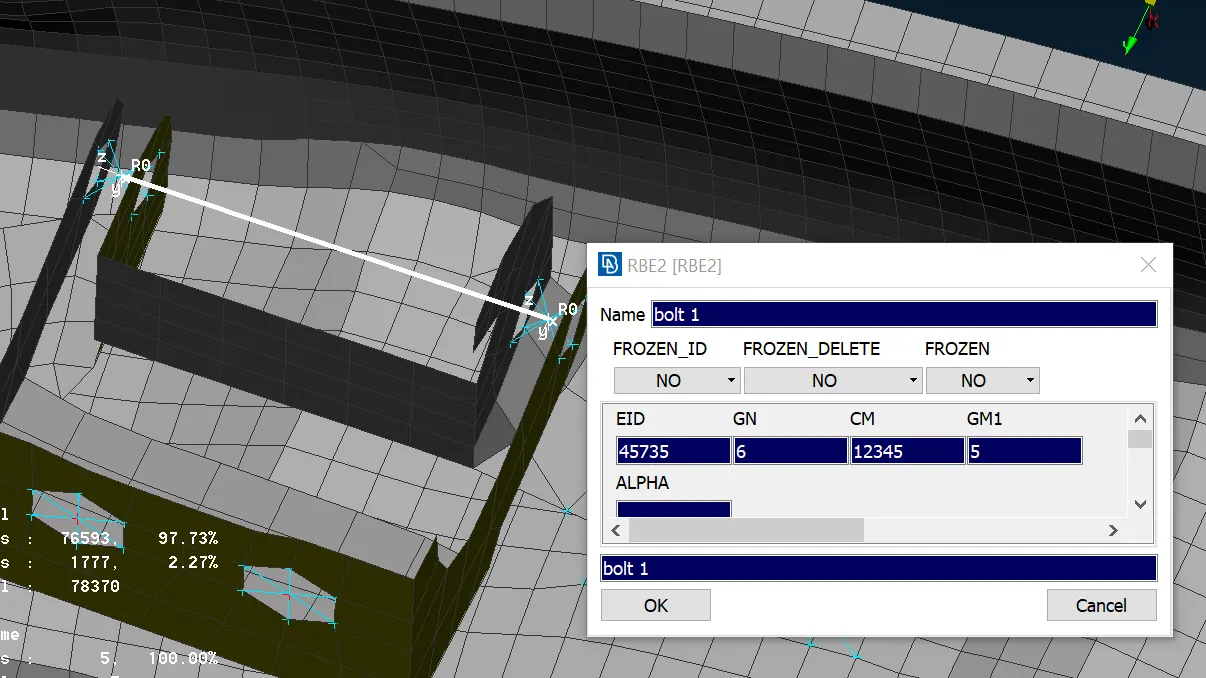
- Hinge connection must be constrained to only five degrees of freedom as this allows the door to open.
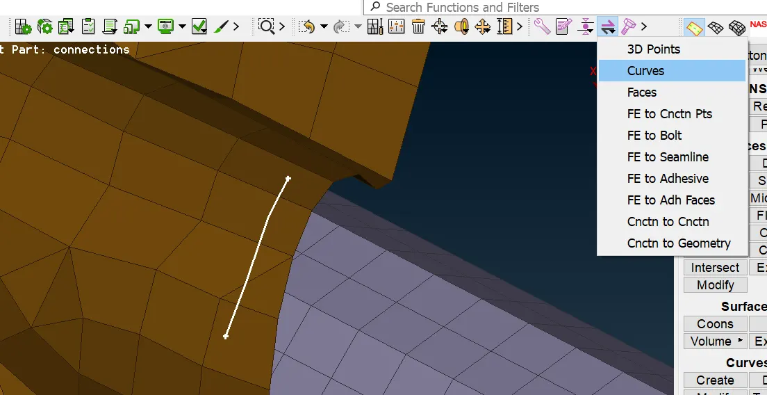
- Spot welds are also parts of connections. In ANSA spot weld can be deployed between different surfaces. Create curve --> convert the curve to spot weld --> Then open connections manager and select the spot weld curve and then assign P1, P2, P3.
- Mostly overlap shell is used when the surfaces are parallel and y joint shell is used in perpendicular surfaces.
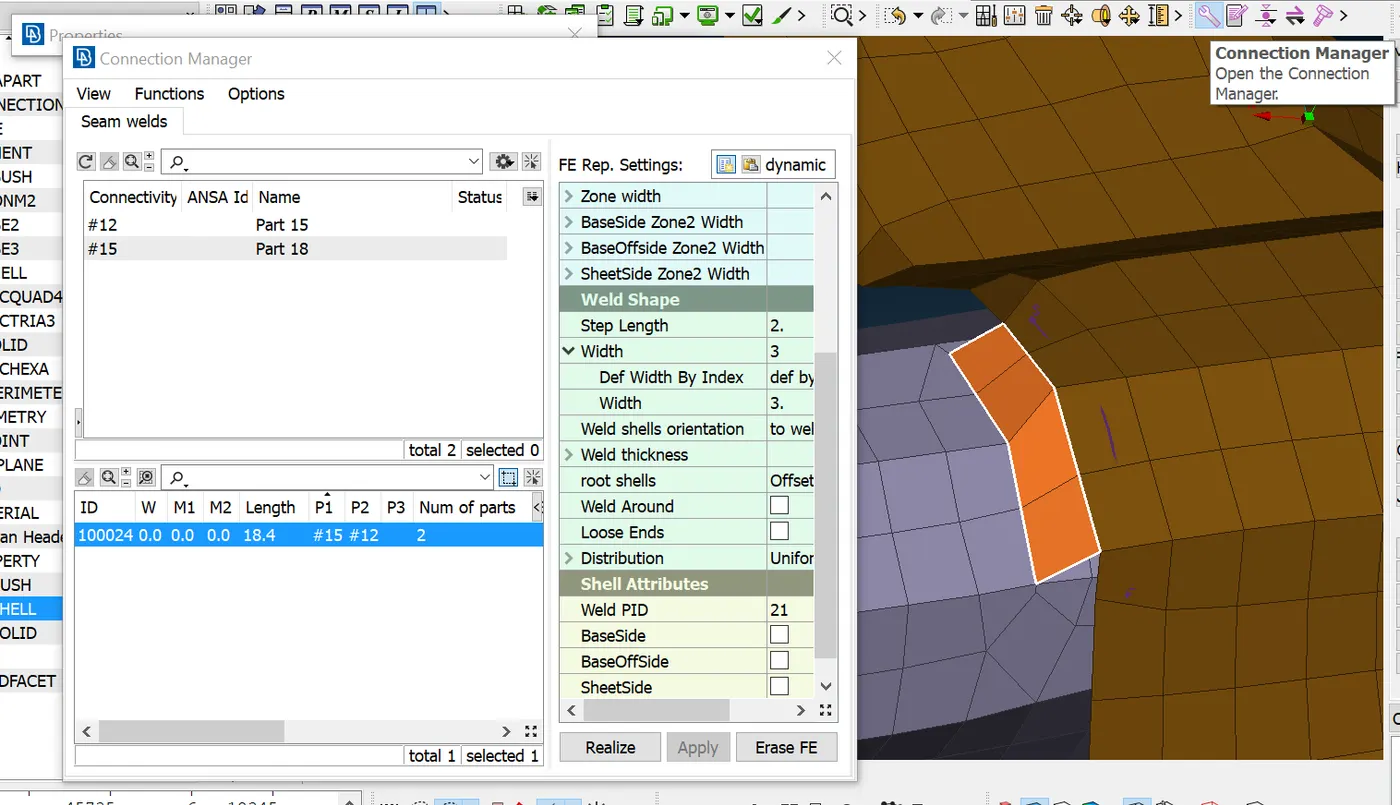
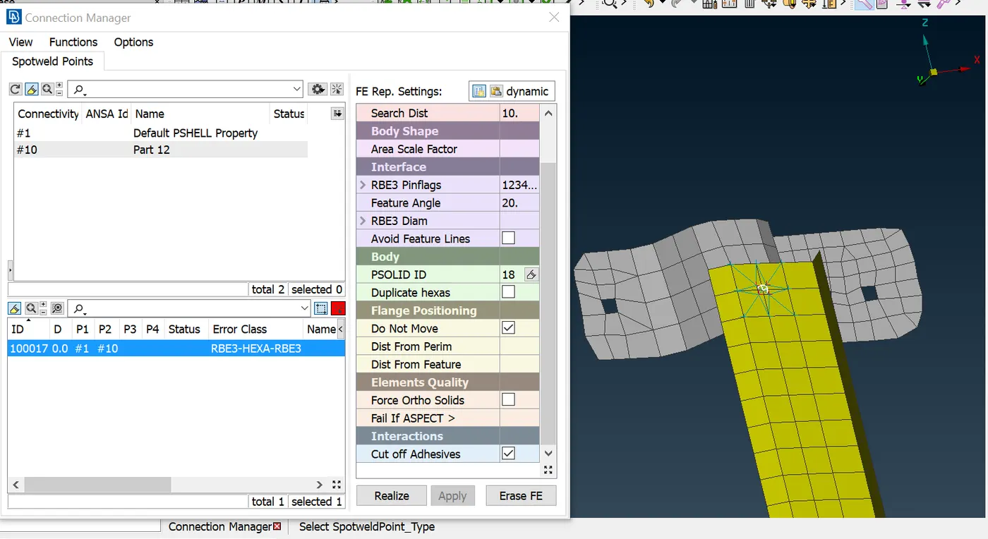
- Spot weld using RBE3-HEXA-RBE3: Create COG --> Convert COG to spot welding point -->Use connections manager to generate RBE3-HEXA-RBE3.
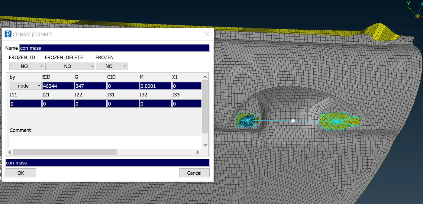
CONMi: It is referred to as con mass. It is basically a concentrated mass connection where a point is created for representing the weight of it. We must give the mass in tonnes. Here we gave the handle mass as 100 grams which is 0.0001 ton.
- CBUSH Connection: This connection for the glass is always given in closed. 1st create curves using Perimeter --> FEAt2Curve option which is available in mesh mode. Then convert those curves to Seam Lines. Now using the connections manager assign ‘P’, and ‘S’ values and select RBE3-CBUSH-RBE3 as the FE type for generating a CBUSH connection.
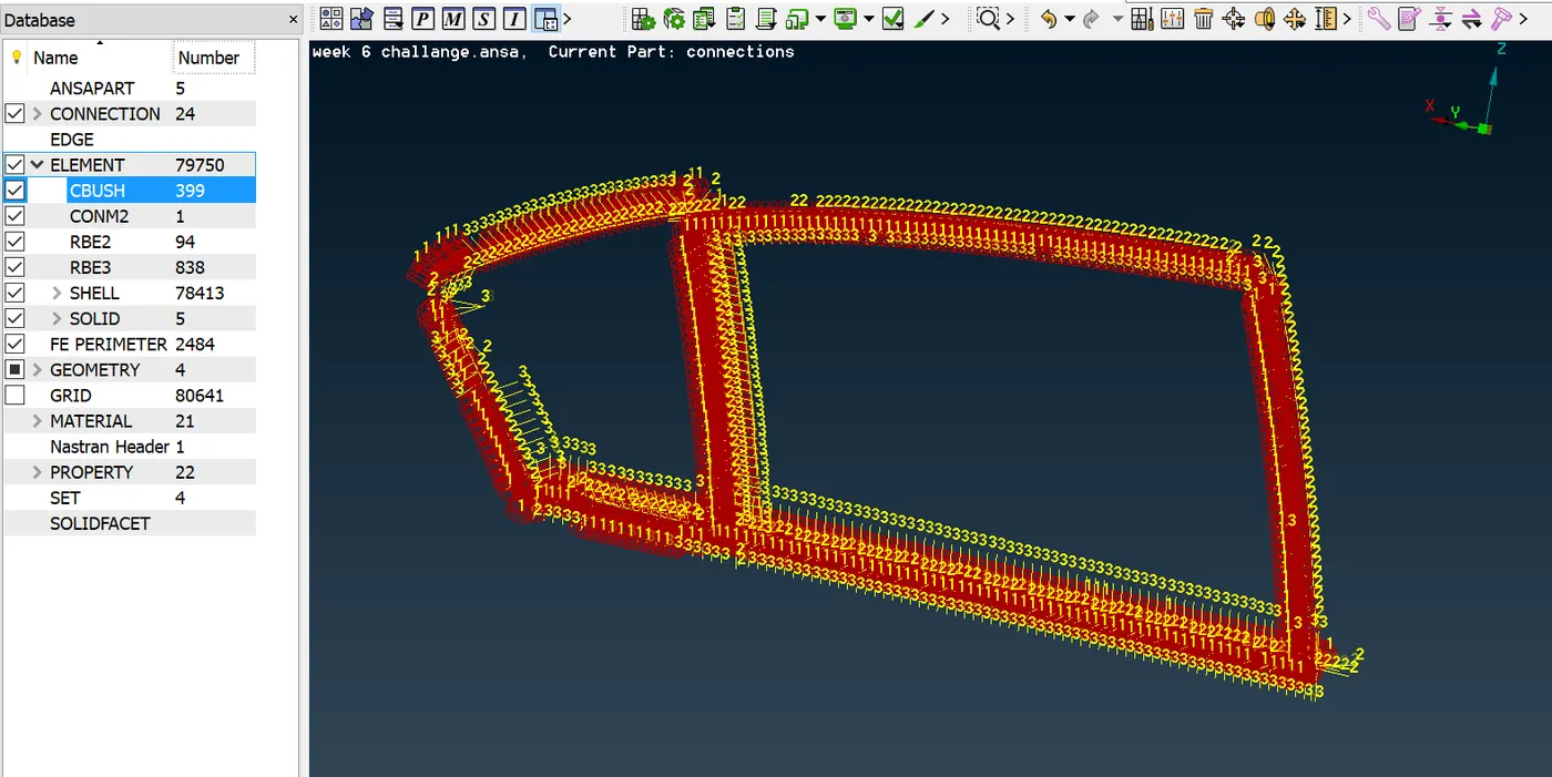
- Generated RBE3-CBUSH-RBE3 Connection has its own Local coordinates which are different from each other. This could create some disturbances during simulation. So, we need to convert all the CBUSH coordinates to Global coordinates. This can be done by changing the CID value to 0 in CBUSH properties.
- We can change all the CID values in a single shot using Modify option.
CONCLUSION:
In this challenge, I have deployed connections with RB2 and RB3 elements successfully. Learned all types of connections used in ANSA.