Project 2
introduction wiring harness is used to route the electrical bundle in an orgonised manner to meet the standards, it is also help wiring in understandable way.
wiring harness on given car body as it is a car backdoor it is recomended to follow the design guidelines.
Step1
Downloading the required connectors from te.com after defining the connectors electrically from the electrical part design workbench.
images are shown below.
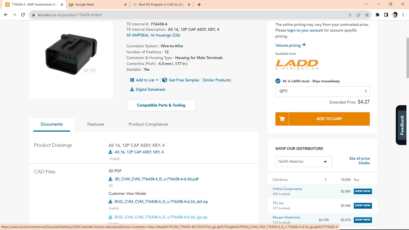
it represents downloading required cad data fropm te conectivity
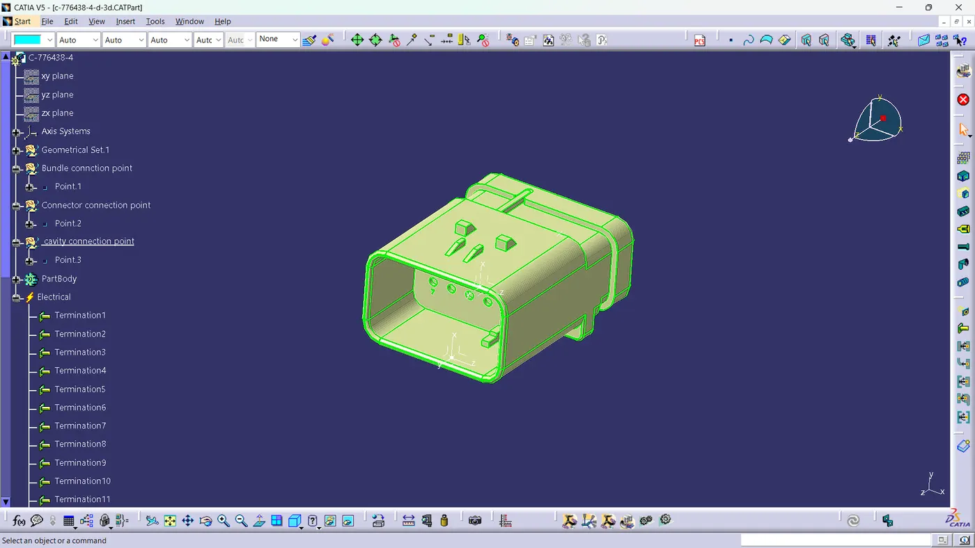
it represents electrical definition to the connectors.
on this way all other connectors are defined.
Step2
From design guidelines it is recomended to fix the interconnector firmly (positive fixations) in this wiring harness i chossen anti rotational connector mounting clip.
images are shown below.
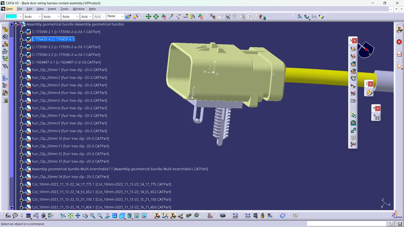
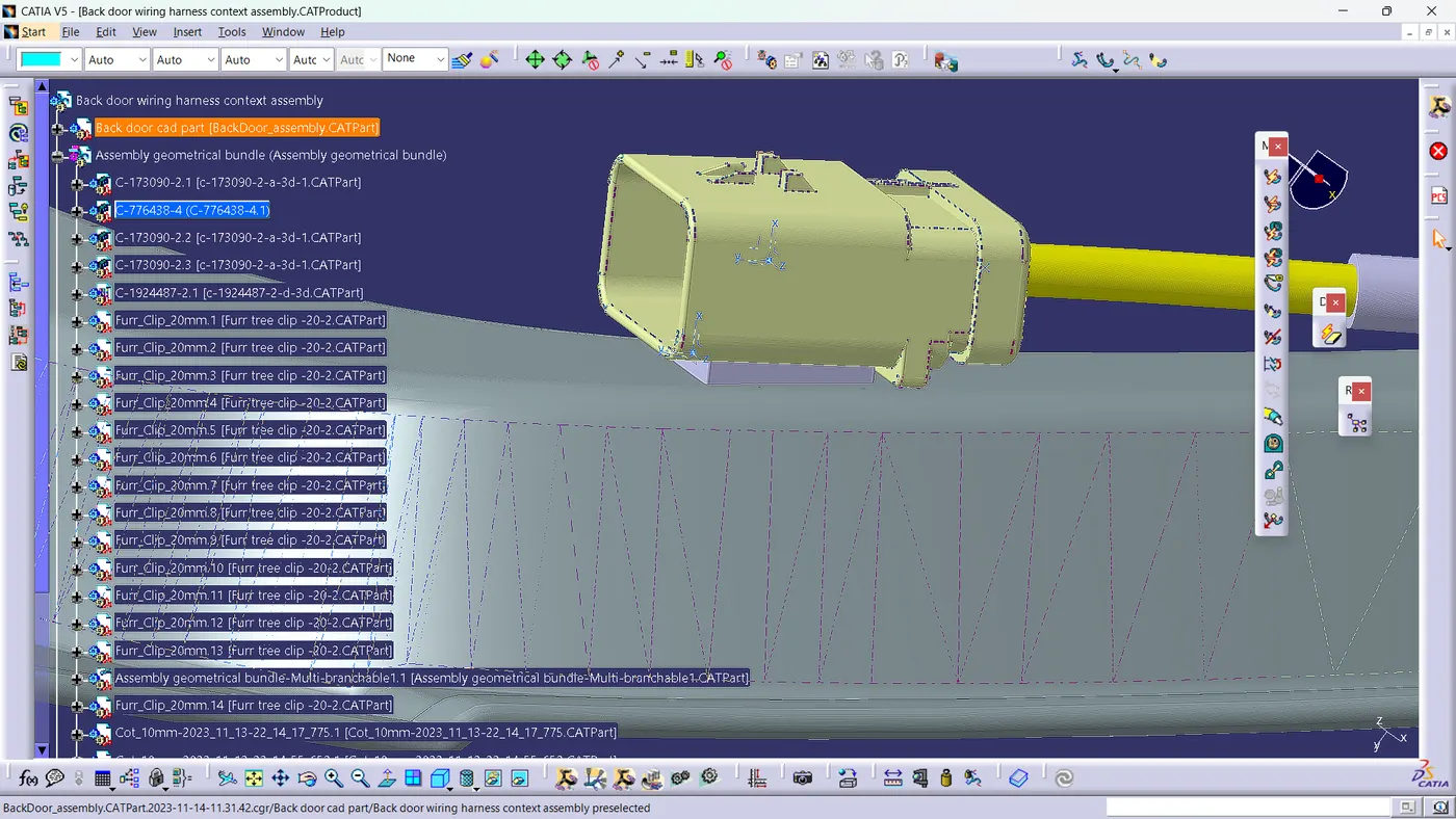
it represents positive fixation with the car body pannel.
Step3
Placing connectors on the car back door pannel. interconnector should be placed near to the top of the back door it should be placed to get connected with the main electric bundle. lighting connector should be placed near to the lighting cavity wiper motor connector should be placed near to the wiper motor emboss.
images are shown below.
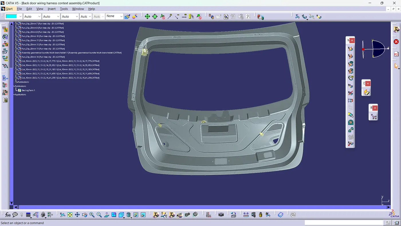
it represents positioning of connectors.
Step4
Placing of support as the wiring harness is placed inside the back door it is not visible from outside it is recomended to use firtree clips which are fixed to the body and zip is wraped around the harness , it is also a cost effective solution.
images are shown below.
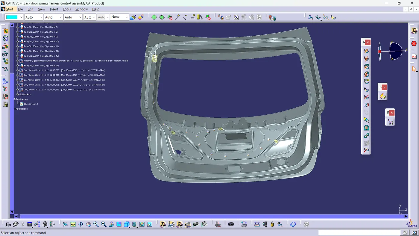
it represents position of support.
Step5
Routing is done from interconnector to the all locations following poka yoke it is recomended to keep the brach point near the location and limiting the branches morethan 4 from the same junction by following all these routing is done properly.
images are shown below.
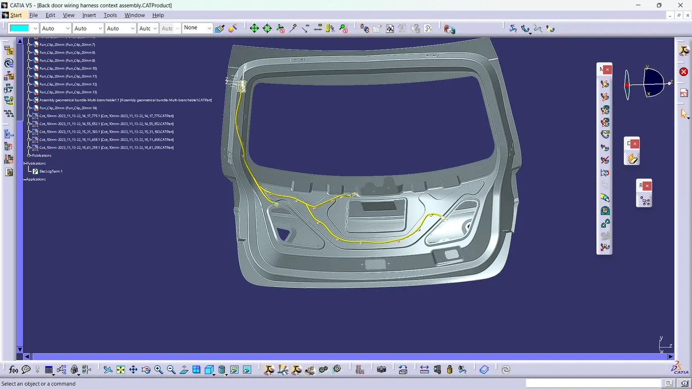
it represents proper routing of wiring harness.
Step6
Checking bundle continuity for the routed wirinhg harness before going to further steps. it heips to achieve manufacturability of wiring harness.
images are shown below.
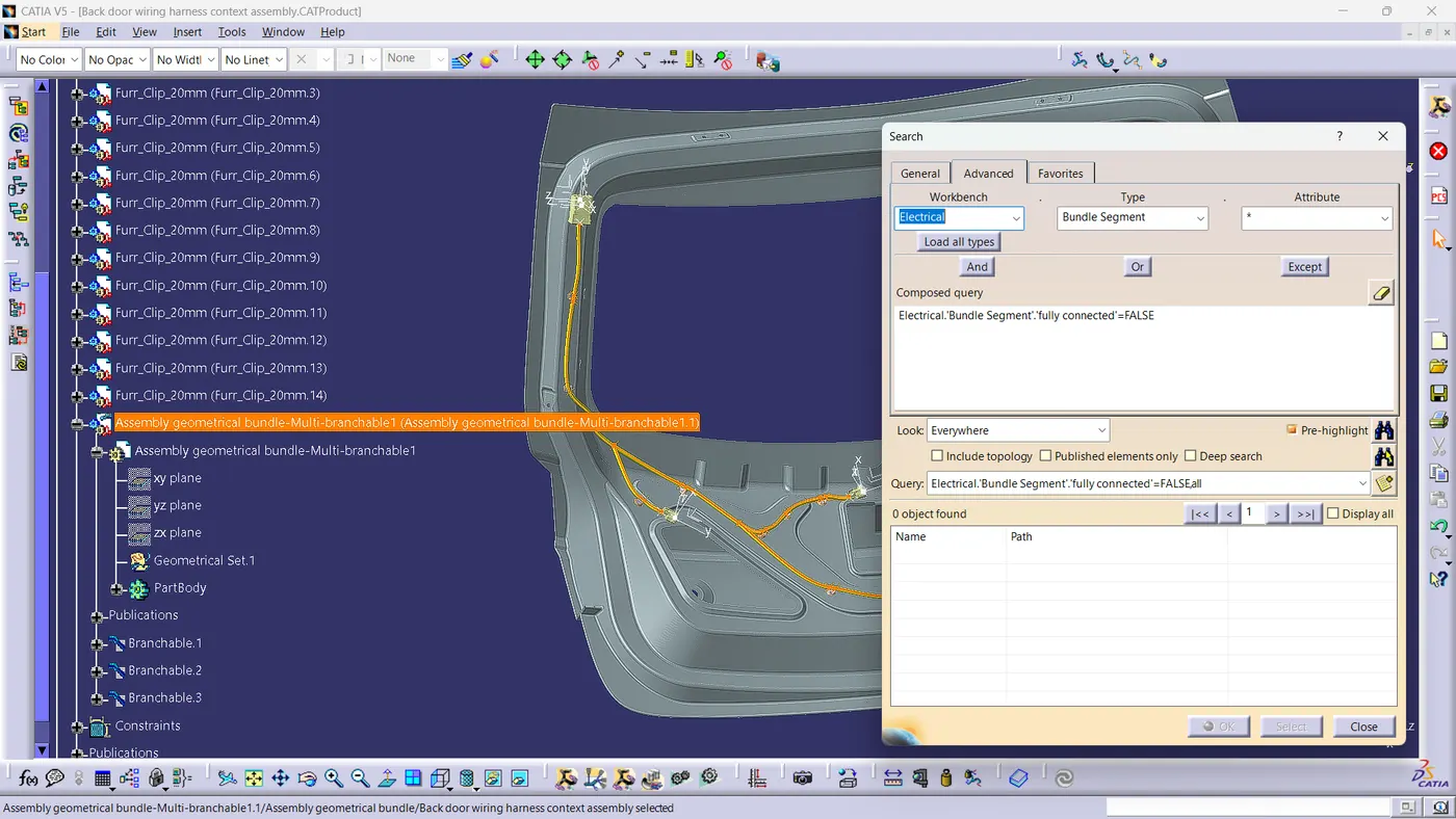
it represents wiring harness bundle continuity check.
Step7
After completing all the checks giving protective covering for the electric bundle. the protective covering will protect the bundle from the harsh environment which gives the durability of wiring harness.
images are shown below.
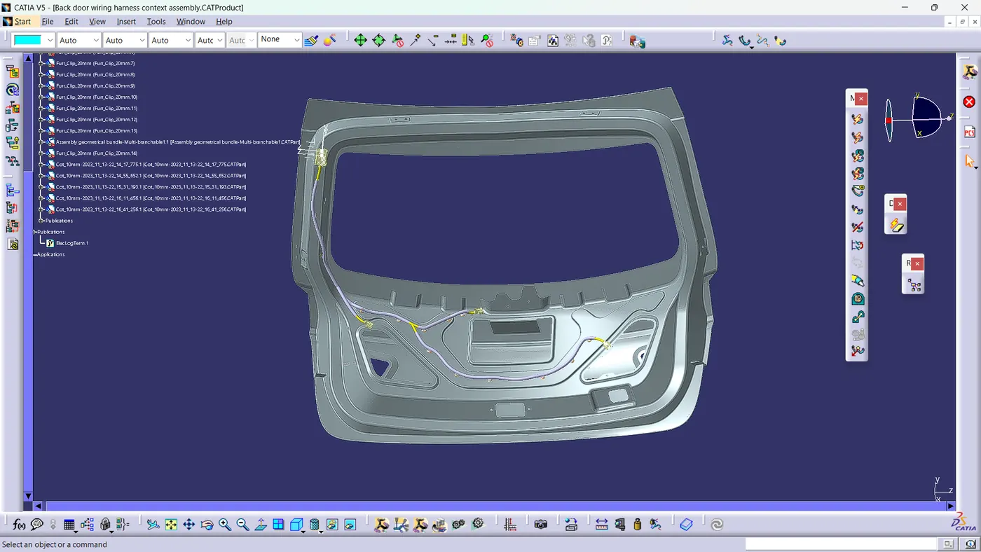
it represents protective covering of electric bundle.
Step8
Wiring harness flatening it will help a person to understand the concept and all topologic information from the flatening of wiring harness, flatening of wiring harness done from the flatening workbench in catia.later drawing file is converted from the flatend .catpart.
images are shown below.
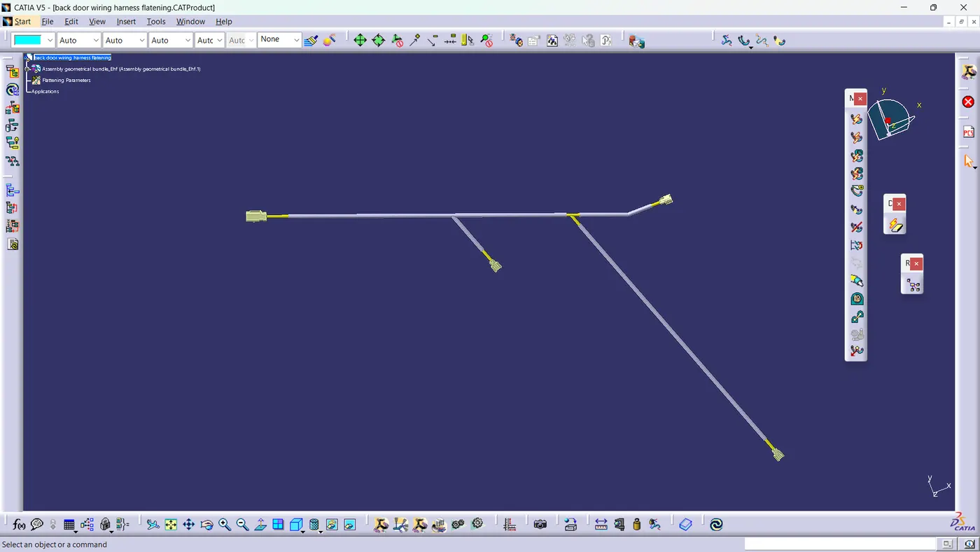
it represents flatrening of a electrical harness bundle.
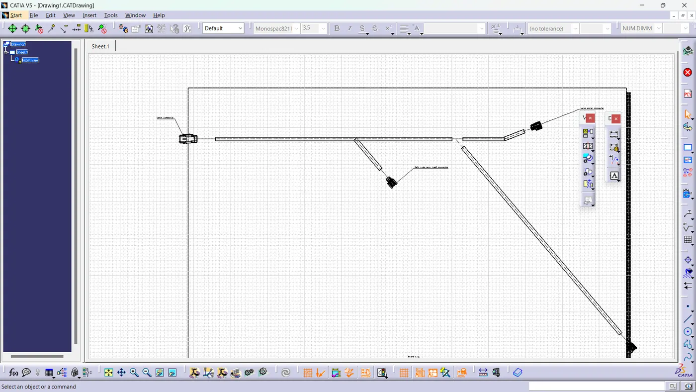
it represents 2D cad data.