Project 2
AIM:
The aim of this project is to create and implement an efficient Wire Harness Routing system for the designated Backdoor, adhering to established design and packaging guidelines.
Objective:
The objectives of this project are as follows:
- Establish electrical definitions for all connectors and catalog them appropriately.
- Precisely position connectors and cavities at their designated locations.
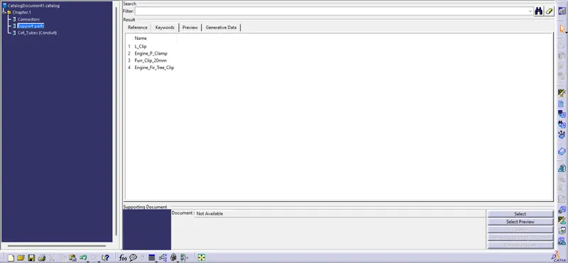
- Strategically position P Clamps and Fir Tree clips according to packaging guidelines.
- Develop the Wire Harness Routing by adhering to the specified requirements and packaging regulations.
- Integrate branch points in the routing as necessary, while maintaining adherence to packaging guidelines.
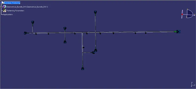
- Create a flattened representation of the Wire Harness Routing.
- Display the flattened view on the drawing sheet.
Design Methodology:
Step 1: Begin by creating a product file named 'Backdoor Wiring Harness Context.' This file will serve as the assembly point for all the necessary part and product files related to the wire harness routing.
Step 2: Next, establish another product file called 'Backdoor Geometric Bundle.' This file will contain the collection of connectors, with the final wire harness routing being a component within this product file.
Step 3: Integrate the Backdoor part, Geometric Bundle file, and any additional required parts or products into the main 'Backdoor Wiring Harness Context' product file.
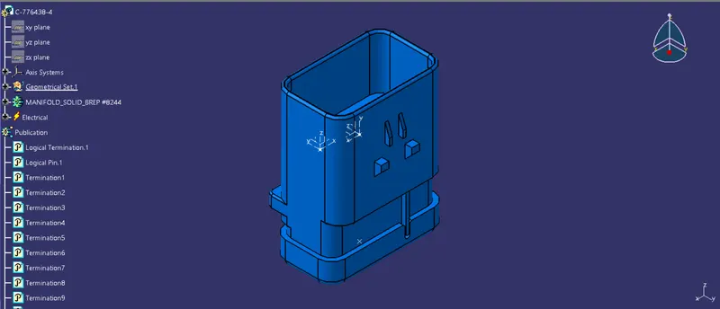
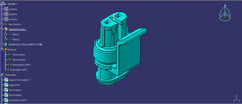
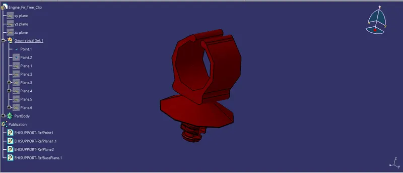
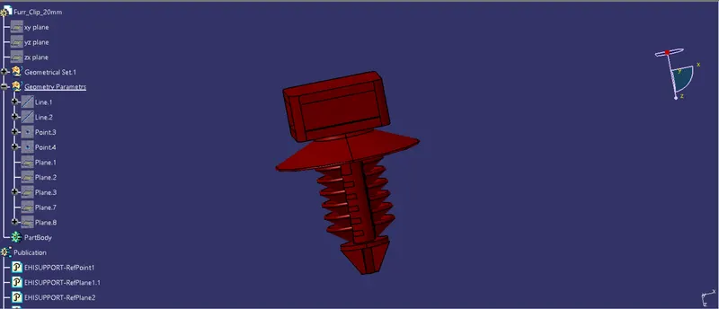
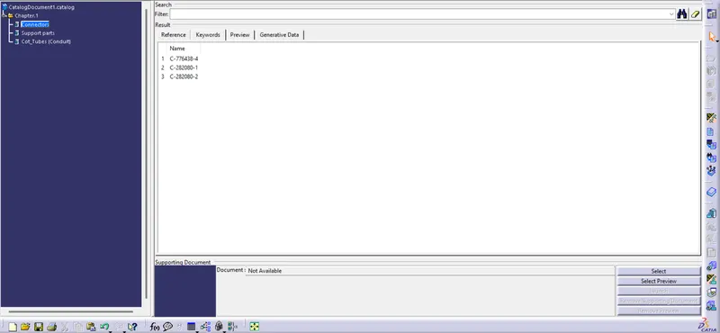
Step 4: Proceed to electrically define all connectors and cavity clips. Define the Connector Connection Point and the Bundle Connection Point, ensuring accurate electrical definitions. As each connector is defined, save it in the Connector catalogue for future reference.
By following this methodology, the design process will progress systematically, ensuring proper electrical definitions and cataloging of connectors for efficient wire harness routing.
ELECTRICALLY DEFINING CONNECTORS:
1. C-776438-4
2. C-282080-1
3. OMEGA FIR TREE:
4. FIR TREE:
SAVING IN THE RESPECTIVE CATALOGUE:
CONNECTOR CATALOGUE:
SUPPORT PARTS CATALOGUE:
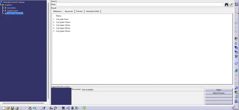
PROTECTION PARTS CATALOGUE:
Step - 5:
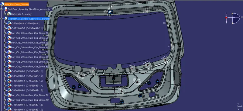
- Add all the connectors to the Geometric Bundle product file and place them using the 'Smart Move' or 'Manipulation Tool' command and the compass into their desired location.
- In this backdoor we need to place the connectors for various purposes like:
- Interconnection Connector (1)
- Brake Light Connectors (2)
- Indicator Light Connectors (2)
- Number plate light Connectors (1)
- Wiper Motor Connector (1)
- Door Lock connector (1)
- Rear camera connector (1)
- The Interconnection Connector is used to connect the wire harness of the backdoor with the vehicle body wire harness.
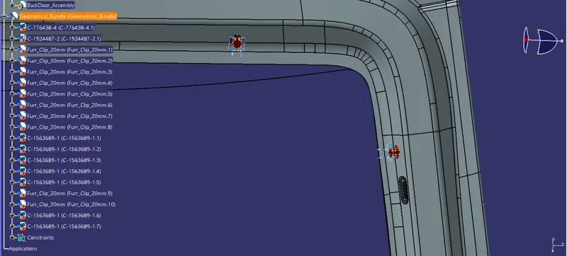
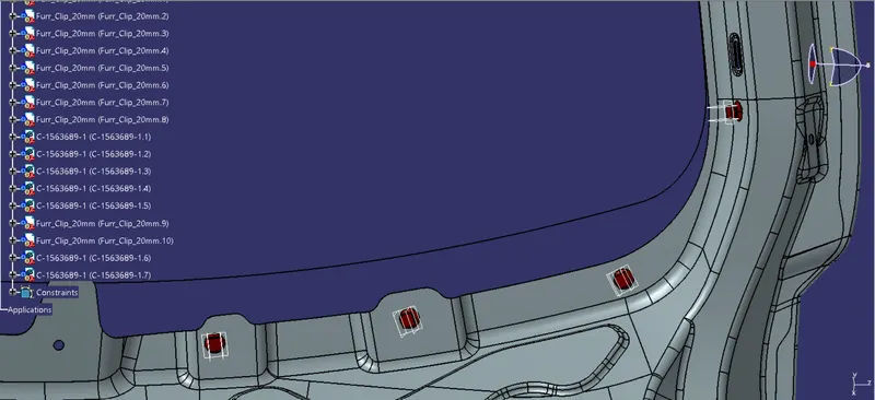
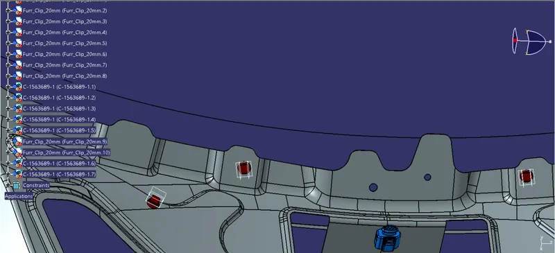
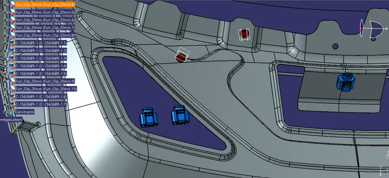
- While placing the Fir tree we must keep in mind that the fir tree cannot be placed in the sealing flange of the backdoor as it will create sealing issues during assembly process and also the wire routing will not be proper.
Backdoor Assembly
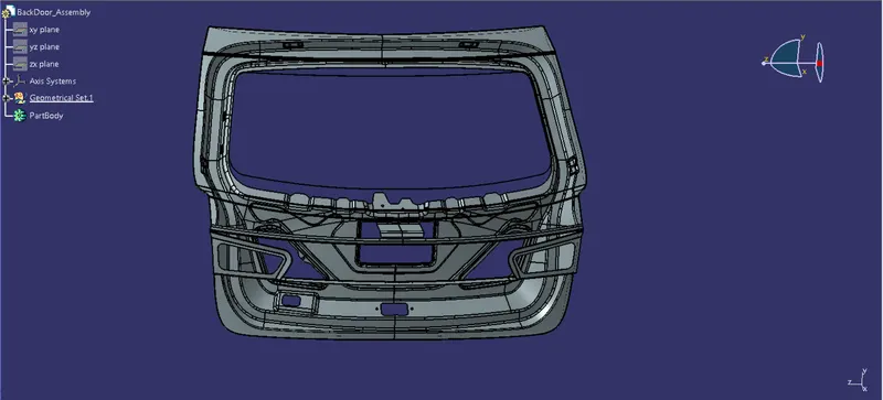
Position of Interconnection Connector
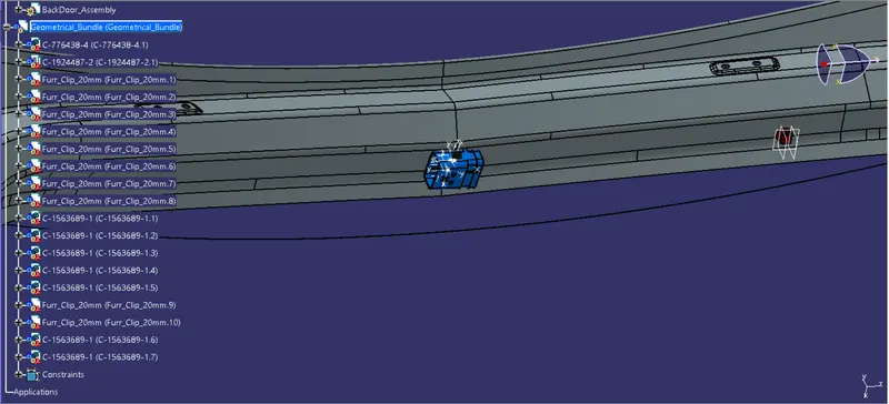
Position of firtree clip
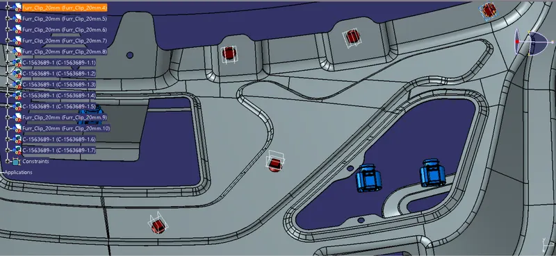
Position of brake light and Indicator sensor (Left)
Position of Brake light and Indicator sensor (Right)
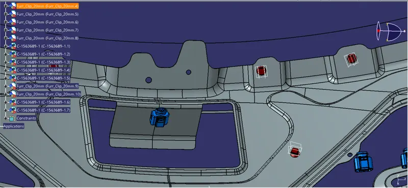
Registration plate connector
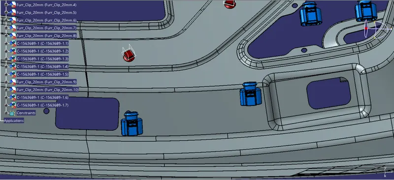
Door handle lock connector
SOME IMPORTANT PACKAGING RULES TO BE CONSIDERED DURING WIRE HARNESS ROUTING AND PLACING OF THE CLIPS AND CLAMPS:
- P - Clamps, Fir tree clips and other clips can be added to the Geometric bundle as they are electrically defined and are part of the Wire harness routing and should be provided with the Wire bundle package.
- The minimum bundle length should be 50mm.
- Enough slack should be provided so that the wiring harness does not get damaged during the Engine rocking or starting condition.
- The wire harness routing should be done in such a way that it is easy in manufacturing and serviceability.
- The wire routing should be done keeping in mind the cost effectiveness of the bundle package.
- To avoid the harness routing and clipping in blind zones of the operator during the assembly and the service.
- Additional slack should be given according to the surrounding and harness bending requirements.
- To avoid giving excess slack and avoid giving slacks wherever not necessary.
- To provide proper slack at end connectors so that there will be no tension on the wire bundle.
- To avoid sharp edges on the sheet metal parts and if it is not possible then provide protection parts to prevent damage of the wire bundle.
- The minimum distance between two straight connection points should be 200mm.
- The minimum distance between clip and the nearest branching point should be 25mm.
- The minimum distance between two breakout points should be 50mm.
- To limit the number of branches from a single branch point to 4.
- To provide separate branch points for separate connectors to ensure Poka-Yoke.
Keeping all the above packaging rules we can start the routing of the wire and provide clipping and clamping wherever necessary during the routing process.
Step - 6:
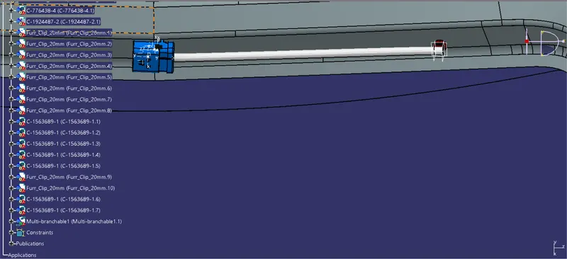
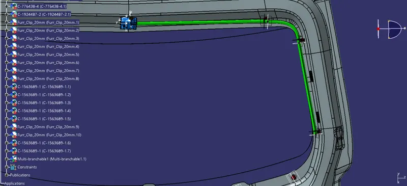
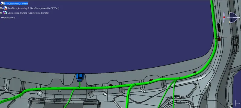
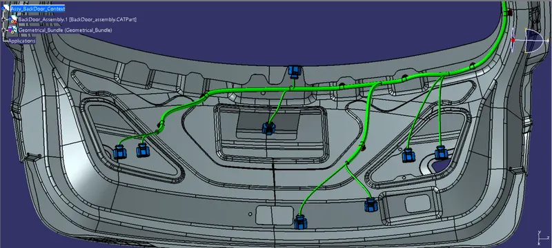
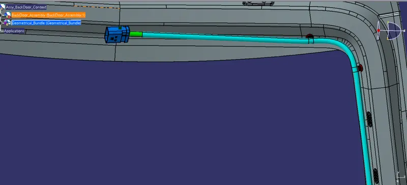
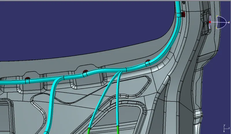
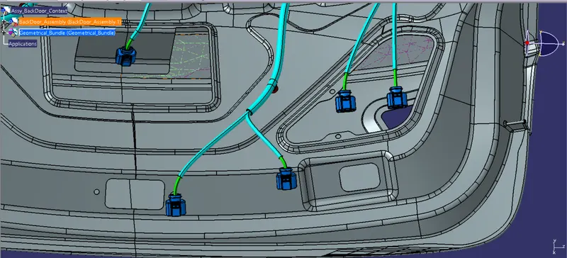
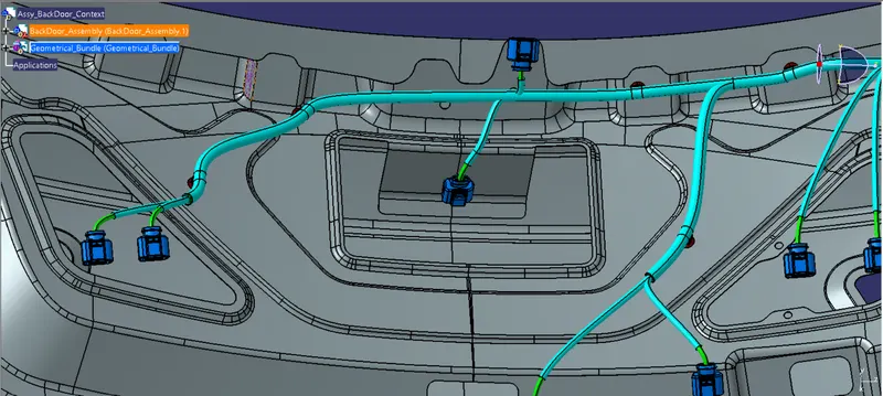
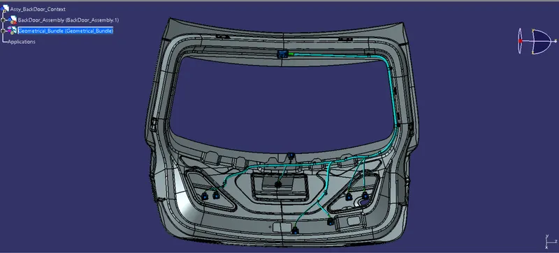
- After placing all the connectors and clamps at the desired location by following the packaging rules, the wire routing is started from the Interconnection connector.
- Further clips or clamps are added during routing depending upon the wire topology and in order to satisfy the design and packaging rules.
WIRE ROUTING:
Step - 7:
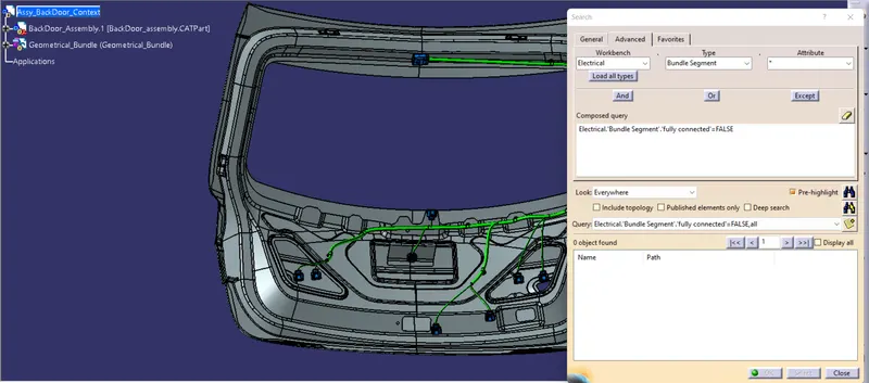
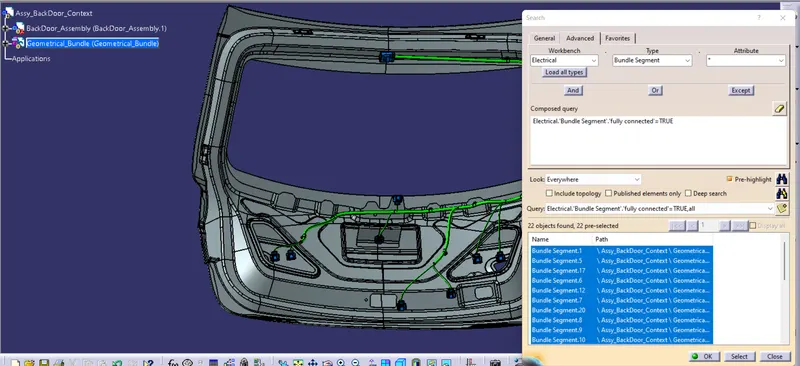
- After completing the routing check for the bundle continuity to ensure that all the bundle segments are fully connected so that there will be no problem during flattening of the wire.
False segments check
True segments check
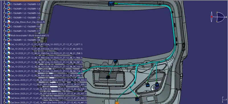
APPLYING PROTECTION PART TO THE REQUIRED BUNDLES:
Step - 10:
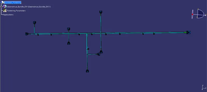
- After finally completing the wire harness routing by following the packaging rules we need to flatten our wire harness assembly.
- To create the wire harness flattening we need to create another product file and navigate to the 'Electrical Harness Flattening' workbench.
- In the workbench first we need to define the Harness Flattening Parameters and then Extract the geometric bundle from the wiring harness context product file.
- Then we can select all the branches and flatten the entire Geometric bundle.
- If all the bundles are fully connected then by selecting 'select all branches' the entire bundle can be selected and flattened.
- The bundles can be rotated and rolled with a proper radius in order to fit the drawing sheet.
WIRE HARNESS FLATTENING:
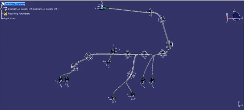
Now we need to flatten the routing using some commands
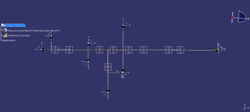
In conclusion, this project has provided valuable insights into the process of wire harness routing for a backdoor or tailgate of a car. We have gained knowledge about the various packaging rules that govern the routing process, ensuring optimal placement of connectors, P Clamps, and Fir Tree clips.
Additionally, we have learned how to flatten the wire harness routing and accurately represent it on a drawing sheet, enabling clear visualization and understanding of the routing layout.
As a result of this project, we now have a comprehensive wire harness routing design for the backdoor. Going forward, we can collaborate with the Engine design team to incorporate the necessary mounting holes for the Fir Tree clips, based on the finalized routing plan. This collaboration will ensure the seamless integration of the wire harness within the overall vehicle design.