Project-1: Powertrain for aircraft in runways
AIM:
POWERTRAIN OF AIRCRAFT IN RUNWAYS
OBJECTIVE:
- Search and list out the total weight of various types of aircrafts.
2. Is there any difference between ground speed and air speed?
- Why is it not recommended to use aircraft engine power to move it on the ground at Airport?
- How an aircraft is pushed to runway when its ready to take off?
- Learn about take off power, tyre design, rolling resistance, tyre pressure, brake forces when landing.
- With necessary assumptions, calculate the force and power required to push / pull an aircraft by a towing vehicle.
7. Design an electric powertrain with type of motor, it’s power rating, and energy requirement to fulfill aircraft towing application. Estimate the duty cycle range to control
the aircraft speed from zero to highest. Make all required assumptions. Prepare a table of assumed parameters. Draw a block diagram of powertrain.
THEORY:
1. Search and list out the total weight of various types of aircrafts.
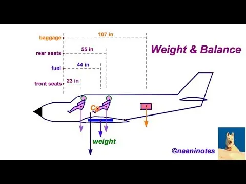
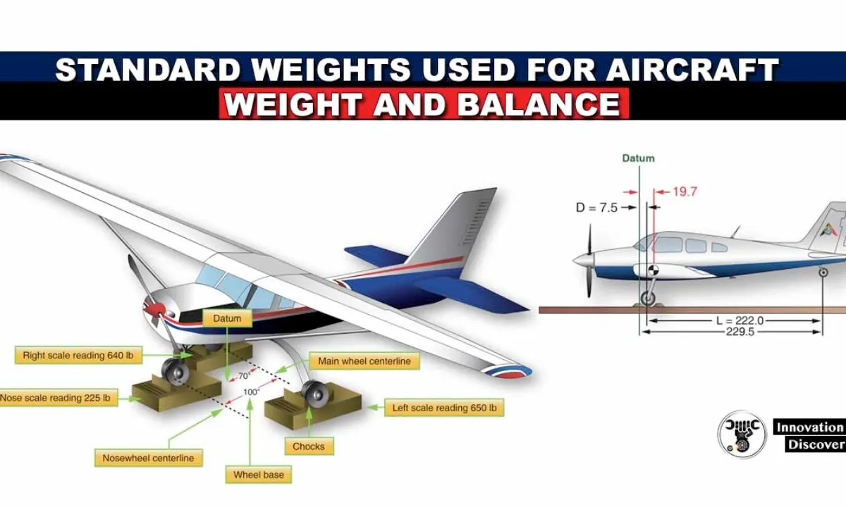
Design Weight Terminology:
Maximum Design Ramp Weight (MRW) :Maximum weight for ground maneuver (including weight of taxi and runupfuel) as limited by aircraft strength and airworthiness requirements.
It is also called Maximum Design Taxi Weight (MTW).
Maximum Design Landing Weight (MLW) :Maximum weight for landing as limited by aircraft strength and airworthiness requirements.
Maximum Design Takeoff Weight (MTOW) :Maximum weight for takeoff as limited by aircraft strength and airworthiness requirements.
(This is the maximum weight at start of the take-off run).
Maximum Design Zero Fuel Weight (MZFW) :Maximum permissible weight of the aircraft less usable fuel.
Operational Empty Weight (OEW) :Weight of structure, powerplant, furnishings, systems, and other items of equipment that are an integral part of a particular aircraft
configuration plus the operator's items.The operator's items are the flight and cabin crew and their baggage,unusable fuel, engine oil,
emergencyequipment, toilet chemical and fluids, galley structure, catering equipment, seats, documents, etc.
Maximum Payload :Maximum Design Zero Fuel Weight (MZFW) minus Operating Weight Empty(OWE).
Maximum Seating Capacity :Maximum number of passengers specifically certified or anticipated for certification.
Maximum Cargo Volume :Maximum usable volume available for cargo.
Usable Fuel :Fuel available for aircraft propulsion.
Types of aircrafts:
Tubro prop aircraft:
The turboprop aircraft has one or more gas turbine engines. They are both connected to a gearbox which turns the propellers. This is contrary to the pistons
or jet engines that are found in the other types of small aircraft. The turboprop airplanes are usually much bigger than the piston aircraft that they resemble and can fly at
much higher altitudes of 35,000 feet. They are well suited to flying for 600 to 1000 miles in a single flight, and a much cheaper option to private jets.
These resemble turboprop aircraft but are much smaller. They have one more piston-powered engines that are connected to the propellers. They are also incapable
of flying at the high altitudes that the turboprop aircraft fly at (15,000 feet) and can cover much less distance (300 to 400 miles). The typical piston aircraft can seat around
one to six people, which seats that are in rows of two. Piston aircraft don’t need long runways to fly and don’t need traffic control towers to navigate.
Narrow body aircrafts:
Narrow body aircraft are also known as single-aisle aircraft since they allow seating in a single row and have a cabin with a diameter of about three to four meters.
This allows for up to 6 abreast seating and down to 2-abreast.The highest seating capacity is 295 passengers. This only occurs with the Boeing 757-300. The size of the
fuselage in a narrow body airplane allows passengers to stand and walk around, but not with much autonomy. There is also room for lavatories and for flight attendants to
attend to the travelers.There are many executive airlines that utilize narrow airplanes with luxury interiors like the Airbus 318 and the Airbus 319.
Airbus is a European manufacturer of airplanes that is registered in the Netherlands but has its services registered in other countries such as France, Germany, and Spain.
It has been operational since 1970 and deals in large planes that can carry a large number of passengers. The first Airbus was the A300, and it was the world’s first twin-aisle
aircraft with twin engines. A smaller version of the A300, the A310, came into existence shortly after.Variations of the aircraft exist such as the A318, A319, A350, A220, and
the A321. These range from airplanes with 2 engines and 2 aisles, to 4 engines and double deckers with twin aisles.

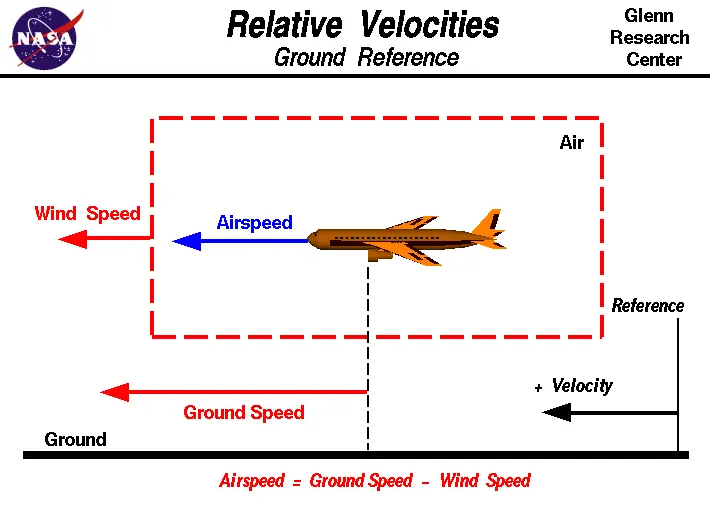
Ground speed on the other hand, is the aircraft’s speed relative to the ground. One thing that should be noted here is that it’s its horizontal rather than vertical speed – an
aircraft climbing completely vertically would have a ground speed of zero.
In other words, while airspeed is what determines whether there is enough airflow around an aircraft to make it fly, ground speed is what determines how fast an aircraft
will get to its destination.
Wind’s Effect on Ground Speed:The relationship between airspeed and ground speed is fairly simple. Ground speed is simply the sum of airspeed and wind speed.
If the aircraft is flying in the same direction as the wind is blowing, the aircraft experiences tailwind, and its ground speed is higher than its airspeed. On the other hand,
if the wind is blowing against the direction the aircraft is traveling in, the aircraft experiences headwind, and its ground speed is lower than its airspeed.
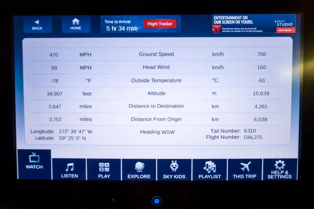
If there is no wind at all, then both the aircraft’s airspeed and ground speed would be the same 500 miles per hour, and the aircraft would reach its destination in four hours.
If there was a 100 miles per hour headwind – wind blowing against the aircraft’s direction of travel – the aircraft would still be traveling at an airspeed of 500 miles per hour.
However, its ground speed would be just 400 miles per hour (100 miles per hour slower than its airspeed). And as such, it would take the aircraft five hours to reach its destinations.
If we consider that there is no wind component then,ground speed = air speed
If wind is blowing in the tail direction of the aircraft then, (air speed > ground speed)
airspeed = ground speed + wind component
If the wind is blowing in the head direction of the aircraft then, (air speed < ground speed)
airspeed = ground speed – windcomponent
Also the gravity too plays a mojor role in increasing the aircrafts speed while it is decending.
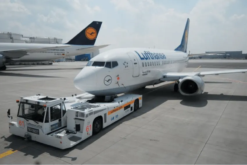
Although many aircrafts are capable of moving in backward using reverse thrust, as result the jet blast or prop wash might cause damage to the terminal building or
equipment. Engine close to ground may also blow sand and debris forward and then suck them into the engine, causing damage to the engine. Therefore there are pushback trucks
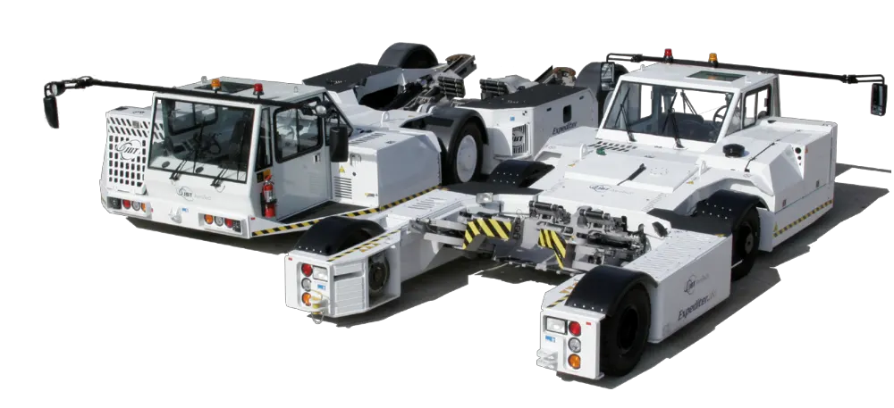
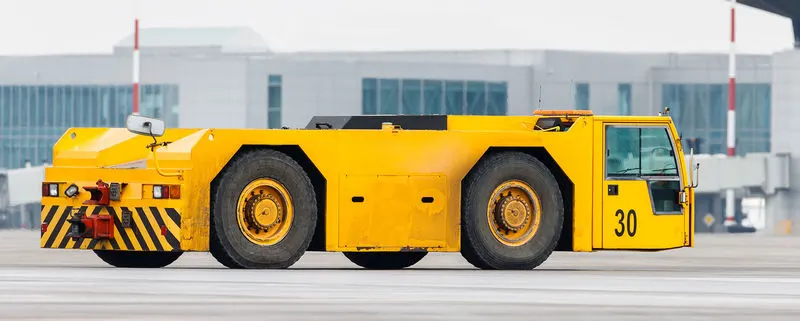
in the airport. A pushback truck lifts the front weel of the aircraft, their role in most airports is to move the aircraft away from the parking spot on to the taxiways, which is called
towing.
Unwanted consequences mainly arising from the unintended movement of the aircraft during engine running.
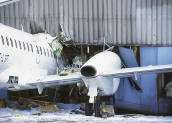
1.Effectively a loss of control can happen, especially during high power engine running. Damage can occur to the aircraft itself, other aircraft nearby or to airside structures.
2.There is a risk of injury to ground support personnel who may be in relatively close proximity to the aircraft.
3.It is easier for truck driver to see the surroundings better than the pilot sitting in the cockpit with limited window. The pushback driver knows the airport better than the pilot.
4.It also saves fuel. virgin Atlantic had proposed a new system in which pushback truck will move the aircraft all the way to runway to save fuel and reduce impact of environment.
5.The plane engines are very loud. When more than one plane will add up their sound, than it will not be pleasent for passangers and others near airport.
4. How an aircraft is pushed to runway when its ready to take off ?
TAXIING: Taxiing is the movement of an aircraft on the ground under its own power while on the suface. The aircraft always moves following the yellow lines, to avoid collision with
the surrounding buildings, vehicle or other aircrafts. The taxiing motion has a speed limit. Before making turn the pilot reduces speed further to prevent tire skids just like other vehicles.
The reason for taxing is to reach the vehicle into runway or from runway to terminal.
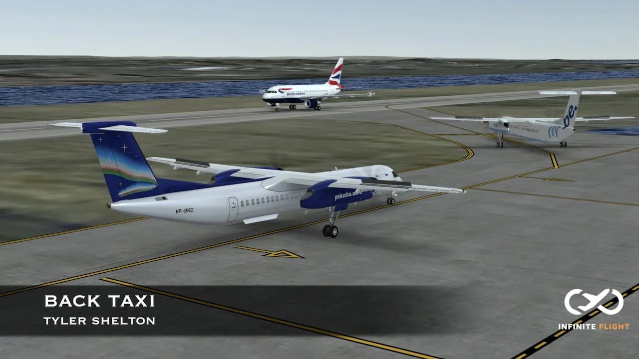
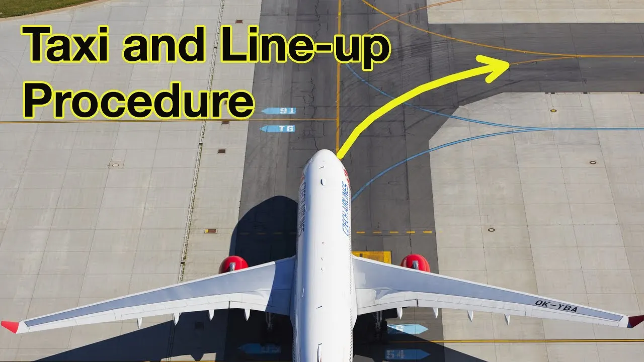
Following the taxiway aircraft reaches the runway. Takeoff is the phase of flight in which an aircraft goes through a transition from moving along the ground (taxiing)
to flying in the air, usually starting on a runway. Usually the engines are run at full power during takeoff. Following the taxi motion, the aircraft stops at the starting line of the runway.
Before takeoff, the engines, particularly piston engines, are routinely run up at high power to check for engine-related problems. This makes a considerable noise. When the pilot
releases the brakes, the aircraft starts accelerating rapidly until the necessary speed for take-off is achieved.
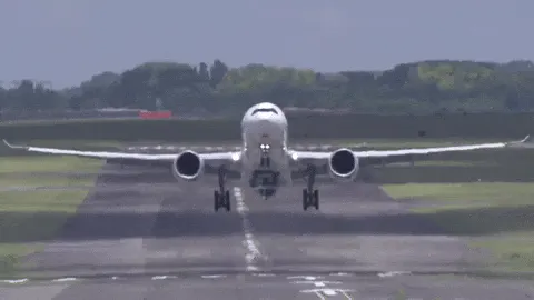
The takeoff speed required varies with air density, aircraft weight, and aircraft configuration (flap and/or slat position, as applicable). Air density is affected by factors such as
field elevation and air temperature.
5.Learn about take off power, tyre design, rolling resistance, tyre pressure, brake forces when landing.
Take off power:
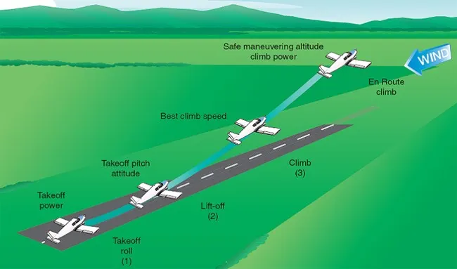
1.Takeoff is the phase of flight in which an aerospace vehicle leaves the ground and becomes airborne.
2. For aircraft that take off horizontally, this usually involves starting with a transition from moving along the ground on a runway
3. The takeoff speed required varies with air density, aircraft gross weight, and aircraft configuration
4. The power from the engine of the aircraft used to achieve the flight is called take off power
5. For light aircraft, usually full power is used during takeoff.
6. Large transport category (airliner) aircraft may use a reduced power for takeoff, where less than full power is applied in order to prolong engine life, reduce
maintenance costs and reduce noise emissions
Tyre Design:
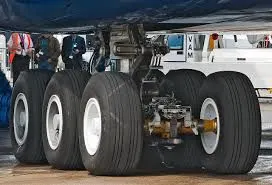
1. The aircraft tyre is usually specially designed as the tyre has to withstand more load and also higher speed at the same time.
2. The number of tyres required for any aircraft increases with aircraft's weight, as the weight of the aircraft needs to be distributed more evenly.
3. Aircraft's tread pattern are designed to facilitate stability in high crosswind conditions, to channel water away to prevent hydroplaning and for braking effect. some of the
tyre design is listed below.
Bias Ply Tyre:
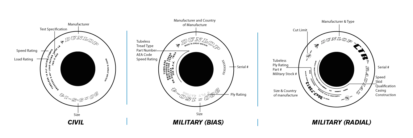
The bias ply tyre consists of casing plies running diagonally at approximate right angles to one another.
The number of plies and the angles at which they are laid dictate strength and load capacity.
High-performance bias aircraft tyres feature inter-tread reinforcing fabric (ITF). This provides additional high-speed stability, reduces tread distortion under load,
protects the casing plies from damage and can act as wear indicators on retreadable tyres.
Radial Tyre:
1.Radial tires are the most modern design of aircraft tyres. It is a design that is similar to that of car tyres.
2.Typically, the radial tyre offers more landings per tread and lighter weight than a bias tyre, though sometimes at the expense of retread lives.
3.Radial aircraft tyres differ to bias aircraft tyres in that the plies all run radially from bead to bead at approximately 90° to the centre-line of the tyre. Angled belt plies
are laid between the tread and the top casing ply, resulting in a flatter tread and adding strength to the tyre.
4. These are some of the common types of aircraft tyres and also there are three key metrics that are used regarding aircraft tyres
Ply Rating:
1.The ply rating of an aircraft tire is used to identify the maximum static rated load capacity and corresponding inflation pressure applicable to specific operational requirements.
2.The ply rating is an index of airplane tyre strength and does not necessarily correspond to the actual number of casing plies within that tyre.
Load Rating:
1.The load rating denotes the maximum static rated load capability of the tyre in lbs.
Speed Rating:
1.The speed rating denotes the maximum rated ground speed in miles per hour to which the tyre has been tested and approved.
2.These are some information about the aircraft tyres.
Rolling Resistance:
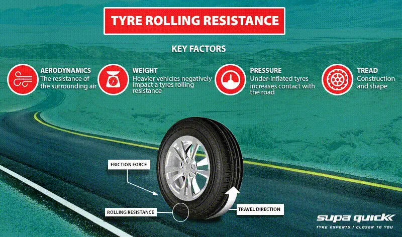
The Rolling resistance force is mainly Experienced by the Tyre when the vehicle moves over any surface.
The rolling resistance force is given by the expression,
Frr = urr * (m.g) ,where (m.g) is the weight in Newton and (urr) is the coefficient of rolling resistance.
The coefficient of rolling resistance (urr) depends on many factors like the ,Tyre pressure,Tyre Temperature, Material of the Tyre, Thread pattern of the Tyre and
also the Road Roughness and Liquids on the Road.
These factors determine the rolling resistance force.
Tyre Pressure:
The pressure generally is very high in an aircraft tire to reduce the rolling resistance and to withstand the weight. Usually it will be around 200 to 300 psi of pressure
and they change based on the type of the aircraft.
Tests of airliner aircraft tyres have shown that they are able to sustain pressures of maximum 800 psi.
Aircraft tyres are usually inflated with nitrogen to minimize expansion and contraction from extreme changes in ambient temperature and pressure experienced during flight.
Brake force while Landing:
The brake force while landing is done by three different process and they are,
Aircraft disc brakes: Aircraft has disc rotors in the landing gear, used to brake the wheels while touching the ground. These brakes are operated hydraulically or pneumatically.
Trust reversers: Thrust reversers allows thrust from the engines to be used to slow the aircraft. This is also very effective in bringing down the speed of the aircraft.
By using a negative angle plane, we are turning the wind that is coming into the propeller to flow in the opposite direction
Air Brake: Air brake dedicated flight control surface that work by increasing the drag force, air brakes are designed to increase drag while making little change to lift,
resulting in a higher stall speed.
These are some of the types of braking methods used to bring down the aircraft's speed while landing the flight.
6.With necessary assumptions, calculate the force and power required to push / pull an aircraft by a towing vehicle.
The power required to push/pull an Aircraft can be estimated by the fillowing three steps,
The forces acting on the aircraft should be analysed
↓
The operating speed should be analysed
↓
The required power can be estimated
1. The forces acting on the aircraft should be analysed:
The forces that will be involved in moving the aircraft with the towing tractor is studied and there are mainly two forces acting in this condition.
1.Rolling Resistance Force
2.Air drag force
The greadability and acceleration forces will not be there that much because the towing tractor operates in such a working environment, so we neglect those two forces.
Rolling resistance force
The Rolling resistance force is mainly Experienced by the Tyre when the vehicle moves over any surface.
The rolling resistance force is given by the expression,
Frr = urr * (m.g) ,where (m.g) is the weight in Newton and (urr) is the coefficient of rolling resistance.
The coefficient of rolling resistance (urr) depends on many factors like the ,Tyre pressure,Tyre Temperature, Material of the Tyre, Thread pattern of the Tyre and
also the Road Roughness and Liquids on the Road.
Here we are taking the heaviest flight as a reference to design our electric powered towing tractor because if we design for heavy application all the light aircrafts
can be push/pulled too.
Calculation:
Weight of the Aircraft (Antonov AN-225) = 640000 Kg
Weight of the towing tractor = 50000 kg (To provide Enough Traction)
Rolling resistance coefficient of towing vehicle (Urr) = 0.001 (Assume)
Rolling resistance coefficient of an aircraft tire (Urr) = 0.006 (Assume)
Rolling resistance force of tow tractor = Urr * (m.g) = 0.001 * (50000*9.81)
Rolling resistance force of tow tractor = 0.49 KN
Rolling resistance force of Aircraft = Urr * (m.g) = 0.006 * (640000*9.81)
Rolling resistance force of Aircraft = 37.67 KN
The total Rolling Resistance Force = Rolling Resistance force of aircraft + Towing tractor = 0.49 + 37.67
The total Rolling Resistance Force = 38.16 KN
Air Drag force
The air drag force is the force that occurs due to the Air striking effect on the vehicle when it moves.
The vehicle moves through a Air medium of particular density value with certain speed ,this causes the air to strike against the vehicles body and it causes a drag force on the vehicle
The Aerodyanamic drag is given by the expresssion,
Fad = 1/2*rho*A*v^2*c_d
Here (Rho) gives the density of air medium,(A )is the frontal area of the vehicle which strikes the air, (v) is the veocity with which the vehicle moves and (c_d )is the
coefficient of drag which varies for different shapes of the frontal area.
The above expression gives the Drag force experienced by the vehicle at particular speed.
Calculation:
The velocity of the Aircraft while Towing = 25 KMPH = 6.95 m/s (Assume)
Density of Air medium (rho) = 1.225 (Assume)
The Frontal area of the Aircraft = 20 m^2 (Assume)
The coefficient of Drag of the Aircraft = 0.026 (Assume)
Air drag force = 0.5 * rho * A * v^2 * cd = 0.5 * 1.225 * 20 * 6.95^2 * 0.026 = 0.015 KN
The Air Drag Force Acting = 0.015 KN (Which is very minimum in Magnitude)
Therefore the total force that the motor needs to overcome = Rolling resistance of the aircraft + Drag force acting on the Aircraft.
Total forces acting = 38.16 + 0.015
The Total Force that the motor needs to overcome inorder to Push/pull the Aircraft = 38.175 KN
The Power Requiered:
The power requireded by the motor is given by the velocity with which the towing operation takes place.
The average speed of Push/Pull = 20 kmph = 5.5 m/s
Power required by the motor = Total forces * velocity = 38.175 KN * 5.5
Power required by the motor = 210 Kw
The torque output of the towing tractor can also be calculated by the below steps,
Fte = T . G / r
where,
Fte – The Total Tractive force (Rolling resistance force + Air drag force) ; T – Torque output ; r – Radius of tire ; G – Gear ratio
For a Heavy Duty Towing tractor we assume,
G – 11 (For delivering high torque) ; r – 25 inches = 0.635 m
T = Fte * r / G = 38200 * 0.635 / 11
The Torque requiered to Push/pull for the above stated condition = 2205 Nm
Now for pushing or pulling the aircraft our electric towing tractor requires the following power and torque figures,
1. Power = 210 Kw
2. Torque = 2.2 KNm
7. Design an electric powertrain with type of motor, it’s power rating, and energy requirement to fulfill aircraft towing application. Estimate the duty cycle range
to control the aircraft speed from zero to highest. Make all required assumptions. Prepare a table of assumed parameters. Draw a block diagram of powertrain.
Energy required to be delivered
↓
Motor selection based on Power requirements
↓
Power Converters To upscale the armature voltage as required
↓
Switching Techniques With Duty Cycle ratio For speed Control Of the Motor
Energy is the capacity to do work. Energy is power integrated over time.
Assuming the operational time of the Towing truck is around 10 minutes for one cycle
10 minutes = 0.16 Hour
Energy (KWh) = Power (KW) * Time (h) = 210 * 0.16
Energy (Kwh) = 33.6 KWh
Therefore the battery must be able to store the energy of 33.6 KWh and should deliver the energy throughout the run time in order for the motor to produce the 2.2KNm of
torque instantaneously.
Thus the storage of energy in batteries with high performance ultracapacitors are selected to fulfill the required power delivery.
Motor Selection:
Here we have selected a BrushlessDC Motor type that has a power rating of 210 KW and with the gear ratio and the transmission it should be able to deliver 2.2KN.m of
torque instantaneously.
The Battery armature voltage (V) = 400V (Assume)
The Battery armature current (A) = 400A (Assume)
For getting the maximum power output from the motor (210 KW), the voltage applied to the motor terminals must be 800V (Assume) at the motor's positive and negative terminals.
Powerconverters:
1. Here we use a DC-DC Boost converter to upscale the voltage level from the battery to the required level so that when supplied to the motor we can get the desiered power
output from the motor.
2. Bidirectional DC-DC converters find applications in places where battery charging, regenerative braking, and backup power are required.
3. The power flow in a bidirectional converter is usually from a low voltage end such as a battery or a supercapacitor to a high voltage side and is referred to as boost operation.
4. During regenerative braking, the power flows back to the low voltage bus to recharge the battery (buck mode). As a backup power system, the bidirectional DC-DC converter
facilitates the safe operation of the vehicle when ICEs or electric drives fail to drive the motor.
5. The boost converter converts the 400V of the armature voltage to a high voltage level of 1000 V.
Speed control of the vehicle:
The electric vehicle uses power from the battery source to drive the motor and then further to drive the wheels in order to move the vehicle.
The speed and torque generated from the motor is very important to drive the vehicle as per the Driver's desire.
If we connect the battery directly to the motor the motor will spin with a speed and torque characteristics which will be based on the full power of the battery voltage.
We does not require full power in all the driving conditions so we need to adopt a power controller between the battery and the motor so that the motor speed may be controlled
by the driver to drive the vehicle as desired.
For controlling the vehicle power we use the soft switching operation technique here.
The amount of power can be controlled by changing the duty cycle value.
Considering the losses we take 80 % of the duty cycle to deliver the maximum power of the motor
Motor terminal voltage = Armature voltage * Duty cycle = 1000 * 0.8
With 80% Duty Cycle the Voltage @ Motor Terminals = 800 V , Which gives the full power with all the gearings, instantaneously.
Thus by varying the Duty Cycle value the speed of the vehicle is controlled.
CONCULSION:
By answering the first five questions the need for Aircraft towing tractor is known and the rest of the project deals with the design of the towing tractors.
The reference Aircraft Taken here is the Heaviest Aircraft ever build and so our designed towing tractor is a heavy duty operational vehicle.
The power requirements are calculated for the particular load to be pushed/pulled and to achieve this power at the motor output, the motor type and its voltage at the terminals
are discussed.
Then the power converters are used to upscale the battery armature voltage to the desiered high voltage value so that the motor may spin at full power and requiered torque
can be achieved using a Bidirectional DC - DC Converter.
Finally the speed control of the vehicle is done with Switching techniques where the duty cycle adjustment can change the motor speed from minimum to maximum.
- The parameters assumed for designing this vehicle is taken from onine references and are listed below
S.No Assumed Parameters Assumed Values
1. Weight of the Aircraft 640000 kg
2. Weight of the Towing Tractor 50000 kg
3. Rolling resistance coefficient of aircraft
tyre Urr (@200 psi in New Asphalt ) 0.006
4. Rolling resistance coefficient of towing tractor
tyre Urr (in New Asphalt ) 0.001
5. The velocity of the Aircraft while Towing 6.95 m/s
6. Density of Air medium (rho) 1.225 Kg/m^3
7. The Frontal area of the Aircraft 20 m^2
8. The coefficient of Drag of the Aircraft 0.026
9. Towing tractor Gear ratio "G" (for high Torque output) 11
10. Towing Tractor tyre radius "r" 0.635 m
11. Operational time of the Towing for one cycle 0.16 Hour
12. The Battery armature voltage 400 V
13. The Battery armature current 400 A
14. The motor terminal voltage for full power output
(Taken with reference from Tesla cars) 800 V @ motor terminals
15. Power converters used Bidirectional DC - DC Boost converter
16. The maximum duty ratio for achieving full power 80%
- The Electric powered Heavy Duty Towing Tractor for Aircraft is designed for opeating in extreme load conditions.