Project-1: Modelling an electric Car with Li-ion battery
Block Diagram for an EV:
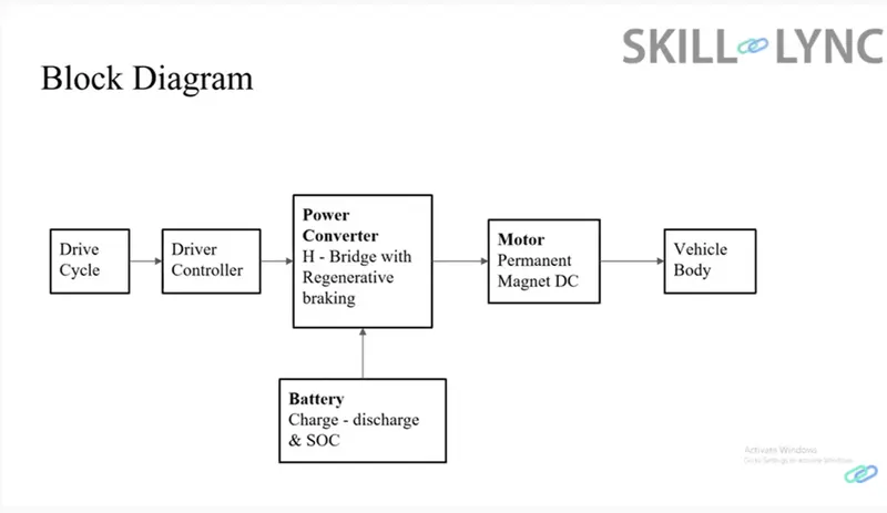
Main components of an EV:
- Tire
- Vehicle Body
- Motor
- Motor Controller
- Power Converter
- Battery
- Transmission System
The electric power required to run the EV's many systems and requirements is stored in batteries. Power converters transform the battery's energy into a form that the motor can use. This conversion may be made from DC to AC or vice versa. The motor is used to propel the vehicle forward or backward while it is moving. The car can produce electricity while braking and send it back to the battery to charge it (regenrative braking). The vehicle's ability to alter speeds as it accelerates and decelerates depends on the transmission system. Tires provide traction for acceleration and braking and limits the transmission of road vibrations to the automobile body.
System level configurations:
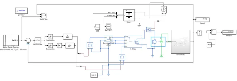
Simulink model-
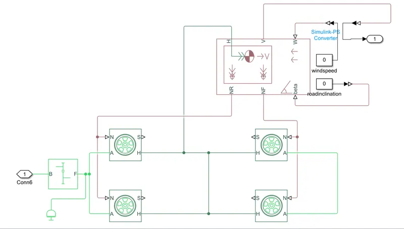
Vehicle body subsystem-
Model parameters:
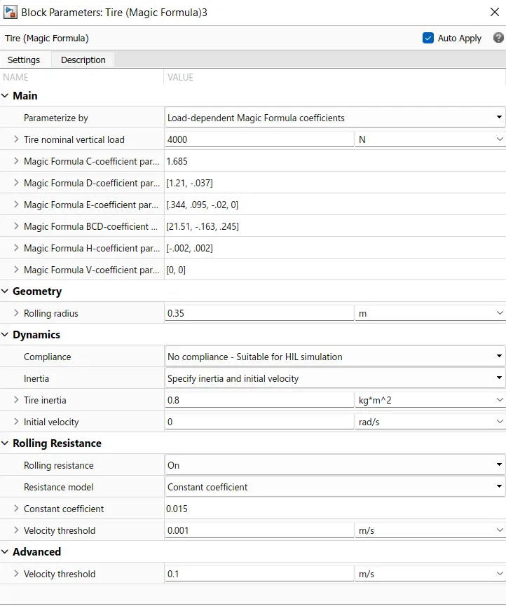
Tires-
Represents the longitudinal behavior of a highway tire characterized by the tire Magic Formula. The block is built from Tire-Road Interaction (Magic Formula) and Simscape Foundation Library Wheel and Axle blocks. Optionally, the effects of tire inertia, stiffness, and damping can be included.
Vehicle body-
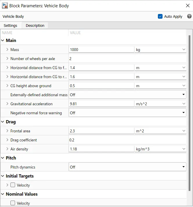
Represents a two-axle vehicle body in longitudinal motion. The block accounts for body mass, aerodynamic drag, road incline, and weight distribution between axles due to acceleration and road profile. The vehicle can have the same or a different number of wheels on each axle. Optionally include pitch and suspension dynamics or additional variable mass and inertia. The vehicle does not move vertically relative to the ground.
Connection H is the mechanical translational conserving port associated with the horizontal motion of the vehicle body. Connections V, NF, and NR are physical signal output ports for vehicle velocity and front and rear normal wheel forces, respectively. Connections W and beta are physical signal input ports corresponding to headwind speed and road inclination angle, respectively. M represents the additional mass. If both variable mass and pitch dynamics are included, the physical signal port J accepts the inertia of the additional mass about its own CG.
Gear-
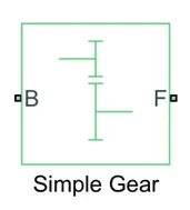
A Simple Gear block with a set gear ratio and no inertial effects to streamline the transmission system of the EV model.
DC Motor(Brushed Type)-
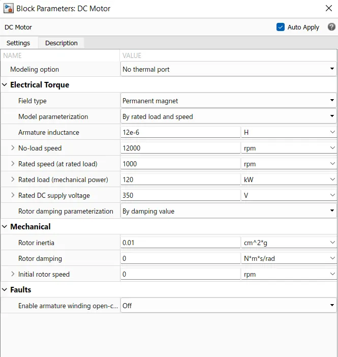
The block assumes that no electromagnetic energy is lost, and hence the back-emf and torque constants have the same numerical value when in SI units. Motor parameters can either be specified directly, or derived from no-load speed and stall torque. If no information is available on armature inductance, this parameter can be set to some small non-zero value.
When a positive current flows from the electrical + to - ports, a positive torque acts from the mechanical C to R ports. Motor torque direction can be changed by altering the sign of the back-emf or torque constants.
Inertia-
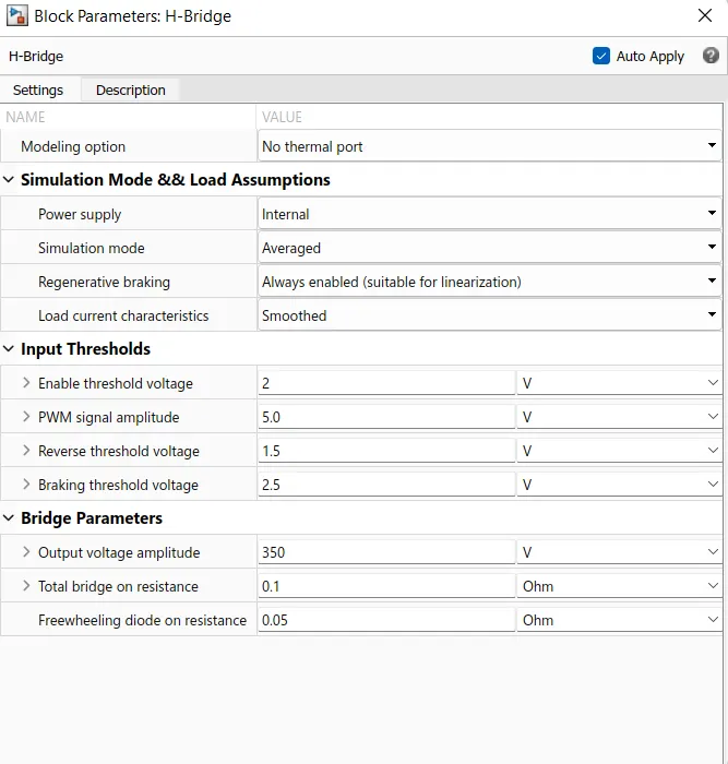
H-Bridge-
This block represents an H-bridge motor drive. The block can be driven by the Controlled PWM Voltage block in PWM or Averaged mode. In PWM mode, the motor is powered if the PWM port voltage is above the Enable threshold voltage. In Averaged mode, the PWM port voltage divided by the PWM signal amplitude parameter defines the ratio of the on-time to the PWM period. Using this ratio and assumptions about the load, the block applies an average voltage to the load that achieves the correct average load current.
For this model, Averaged mode is selected.
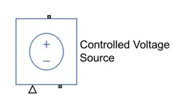
Controlled Voltage Source-
The block represents an ideal voltage source that is powerful enough to maintain the specified voltage at its output regardless of the current passing through it. The output voltage is V = Vs, where Vs is the numerical value presented at the physical signal port.
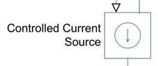
Controlled Current Source-
Converts the Simulink input signal into an equivalent current source. The generated current is driven by the input signal of the block.
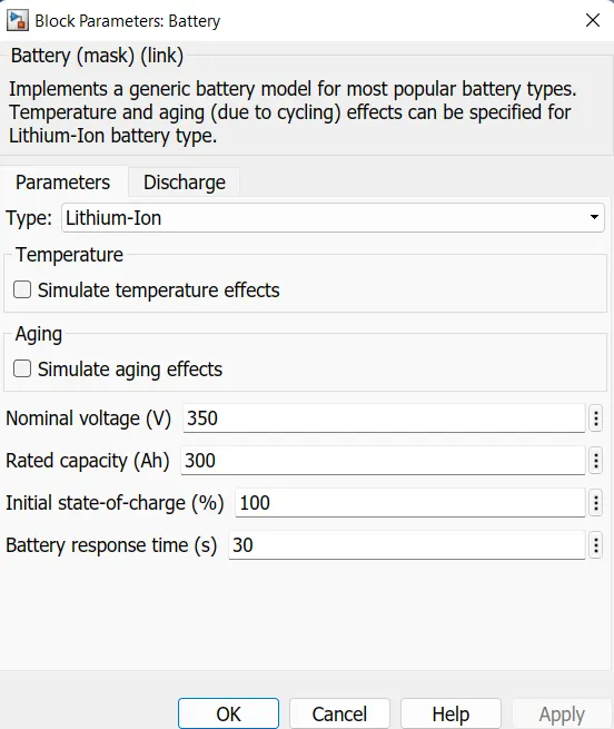
Battery-
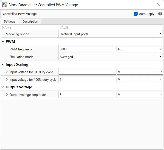
Controlled PWM Voltage-
PID Controller-
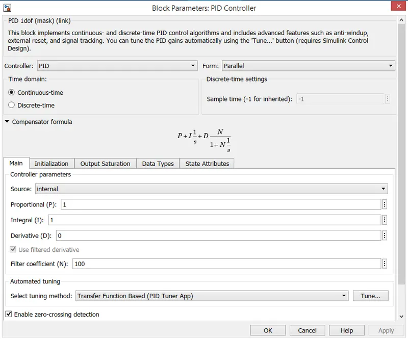
The EV model's speed control depends on the PID controller block. The PID controller block attempts to reduce the error data between the drive cycle data and the actual speed of the vehicle (which it receives from the sum block).
Drive Cycle Source-
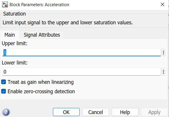
Acceleration-
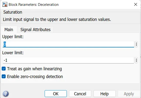
Deceleration-
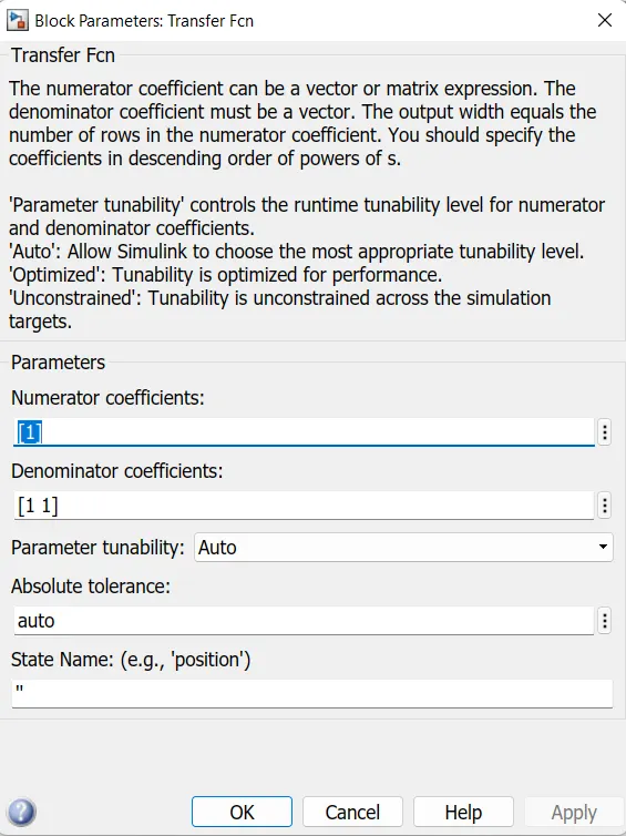
Transfer Function-
The transfer function block is used when we want to insert a transfer function. A transfer function is defined as the ratio of the Laplace transform of the output of a system to the input of a system.
Results:
For WOT Cycle-
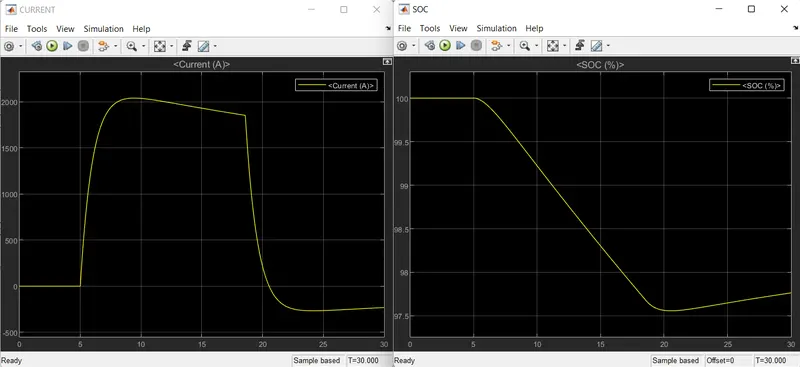
- SOC and Current
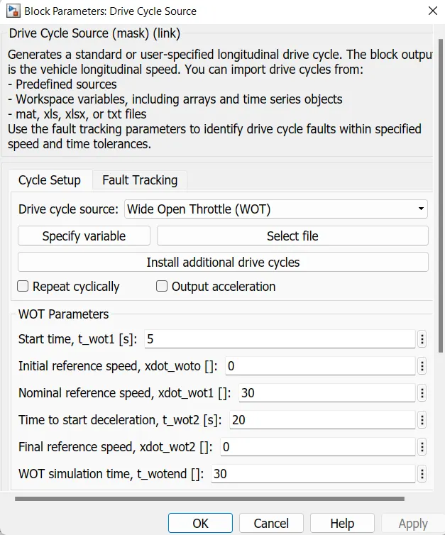
Following are the plots for current and battery SOC respectively. The SOC is reduced from 100 to approximately 97.5 for the given drive cycle.
- Distance Travelled
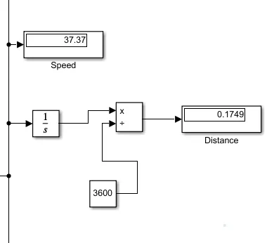
The total distance travelled by the vehicle is 0.17 km with a speed of 37.37m/s.
- Speed
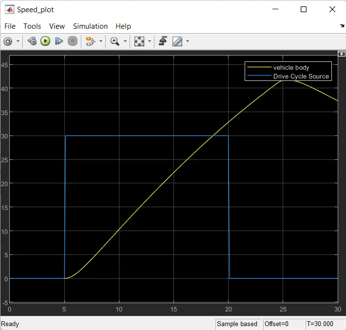
- Untuned System
The result below is for the untuned system where PID Controller is kept with default value of Kp=1 and Ki=1.
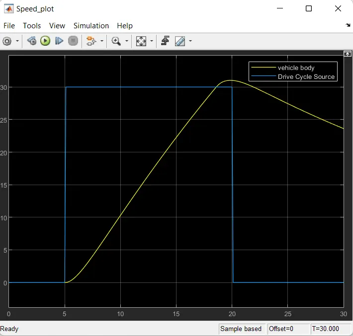
- Tuned System
The result shown is for the controlled system with better response with Kp=20,Ki=1.
For FTP75 Cycle-
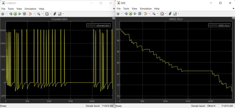
- SOC and Current
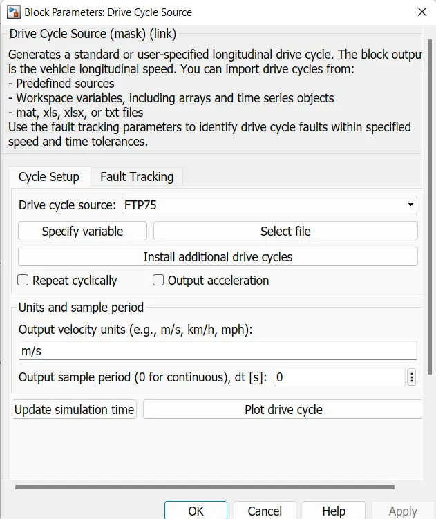
Following are the plots for current and battery SOC respectively. The SOC is reduced from 100 to approximately 72 for the given drive cycle.
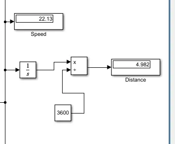
- Distance Travelled
The total distance travelled by the vehicle is 4.98km with a speed of 22.13m/s.
- Speed
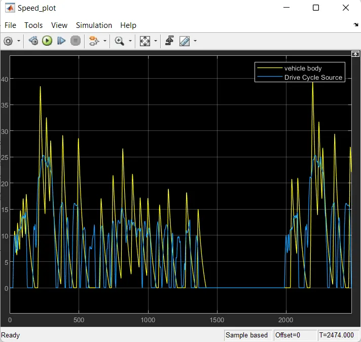
- Untuned System
The result below is for the untuned system where PID Controller is kept with default value of Kp=1 and Ki=1.
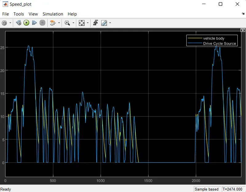
- Tuned System
The result shown is for the controlled system with better response with Kp=20,Ki=1.
Conclusion:
- A simple and low run-time vehicle model using PI controller, brake and accelerator commands avoidng readymade driver block for speed control.
- The SOC, current in the vehicle battery is observed.
- The design for an electric vehicle is modelled. Further, the controlling part can be optimised with improved with control gains.
- The travel distance of the vehicle can be increased by increasing the motor rated load,battery capacity and depending on the forces acting on the vehicle.