Week-7 Challenge: DC Motor Control
Ans 1(A)
Pulse Generator : Generate square pulses of 50% duty cycle i.e On duration having amplitude 1 and for the simulation time interval of 50 second (Amplitude, pulse wieth, phase delay, period).
Controlled voltage source : Regardless of the current flowing through it,the source maintains the output voltage.
Controlled PWM Voltage source : Calculate Duty cycle based on reference voltage across + vref and - vref.
a)output voltage parameter: Determines the amplitude of the output voltage
100∗Vref−Vmin/Vmax−Vmin *100%
Vref+ and Vref- voltage across the ref+ and ref- ports respectively
Vmax and Vmin are max and min reference voltages.
Solver configuration : It is used to specify simulation options for your physical system, such as the type of solver to use, initialization options, and the sample time for the simulation
H-Bridge:It consists of load at the centre and 4 mosfets Q1,Q2,Q3 and Q4 are connected in a bridge manner with diode connected across them each pair of them conduvct for +ve and -Ve half cycle of square wave resulting in forward and reverse motor rotation.
Note: Duty cycle is directly proportional to the speed and current
Simulink PS converter: Converts simulink signal to physical signal
PS Simulink converter: Converts physical signal to simulink signal
DC Motor : Block consists of parameters like Back emf, Armature resistance,Armature inductance,Torque, No load and Rated speed
Ra:1 ohm
La:0.01 H
Wnl : 1500 rpm
Wfl: 4000 RPM
Ideal rotational motion sensor: a device that converts an variable voltage between two nodes into a control signal proportional to acceleration, angular velocity, or position (angle).
Ans 1.B)
please find detailed explination for armature current in pdf form
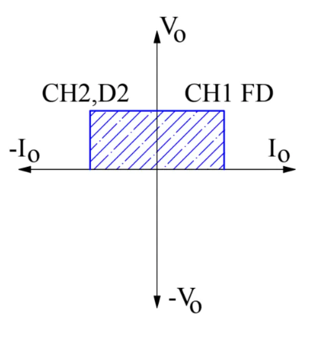
Ans 1.C) Comparison between the Four-Quadrant Chopper DC Drive (DC7) block and H-drive
4 quadrant chopper is used for forward and reverse motoring and breaking operations however H- Bridge is used for forward and reverse motor rotation and not for regenerative braking.
Regenerative braking is possible in case of 4 quadrant chopper.
H-bridge circuit are used in Robotics and other applications for forward and backward rotations of motor.Four-Quadrant Chopper circuit is used for electronic sitching devices and circuits used in power control and signal applications.
For system stabilization and armature current control PI regulator is used in case of 4-quadrant chopper which is not used in H-drive
4- quadrant chopper is better than H-bridge in terms of power storage and Efficiency
Heat losses are less in 4 quadrant chopper as compared to H-bridge
Ans 3)
BLDC motor working
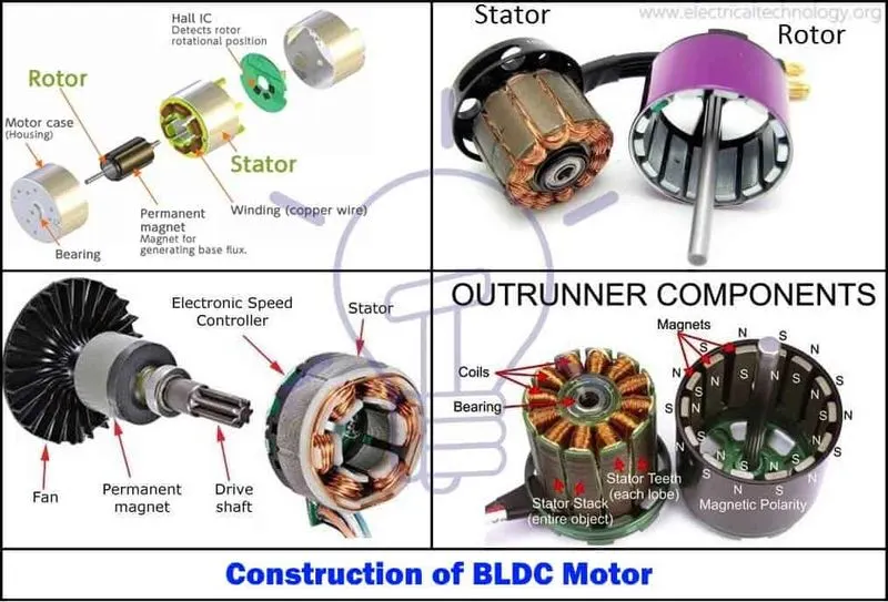
working principle as follows:
3 phase supply is given to the stator winding causing uniform mangnetic field that links with rotor and there is interlocking between stator and rotor ehich results in rotation of motor
It follows lorentz force principle that is when current carrying conductor placed in magnetic field it experiences the force
Force between electromagnet stator and permenent magnet rotor results in motor rotation
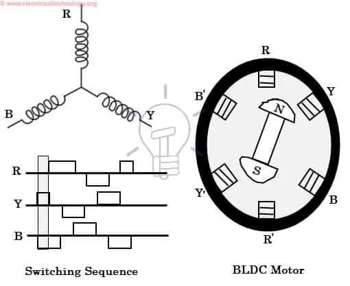
Above figure shows that for given pulses of deired duty cycle motor follow clockwise rotation for North-south and south-north allignment (attraction) and north-north and south-south allignment (Repulsion)
The motor continuous rotation depends on the switching sequence around the coils.
Hall sensors give shaft position feedback to the electronic controller unit.
Based on this signal from sensor, the controller decides particular coils to energize. Hall-effect sensors generate Low and High level signals whenever rotor poles pass near to it. These signals determine the position of the shaft.
2.Ans
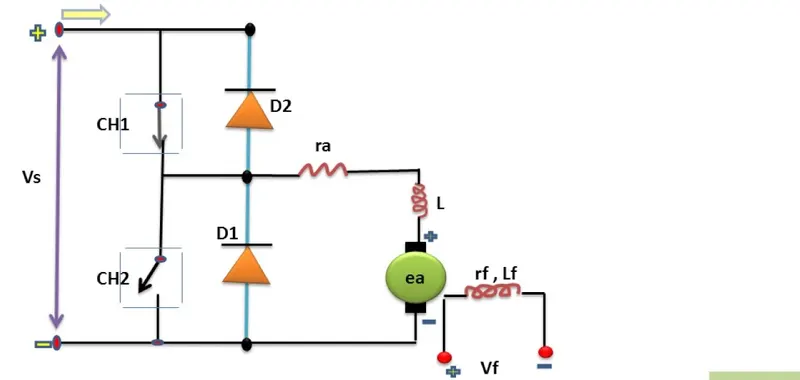
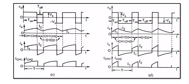
1) When DC voltage applied across CH1 and CH2 for +ve Pulse input Load voltage gets equal to source voltage
vs-CH1-ra-Load-vs
The direction of load current is from source to load
2)When CH1 switched of freewheeling action takes place through D1 I0 changes exponentially due the effect of inductance as it dosent allow sudden change in current and lie down ot zero
3)When CH2 is made off E drives the circuit and current fow is from E-load-CH2-Load
current obtain is exactly opposite to that previous Vo/p is 0.
4) Once CH2 turned off, D2 gets forward baised Vo/p is VS
Path of current as follows E-drive-LA-Ra-D2 and Vs