Project 1
Design a DC-DC SEPIC converter with input voltage = 10 V, output voltage = 0-20V
Take f = 50 kHz, ΔI1=ΔI2 =0.2 A, , Δv1=Δv2 =0.2V.
Find the state space model of the converter
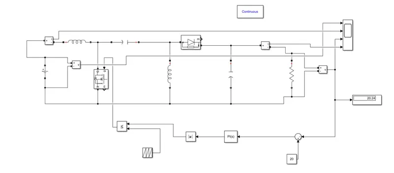
Construct the converter in MATLAB and simulate
Obtain the waveforms for input and output voltage, inductor current and capacitor voltage
Repeat the above for Cuk converter
Compare the results
The single-ended primary-inductor converter (SEPIC)
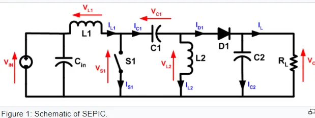
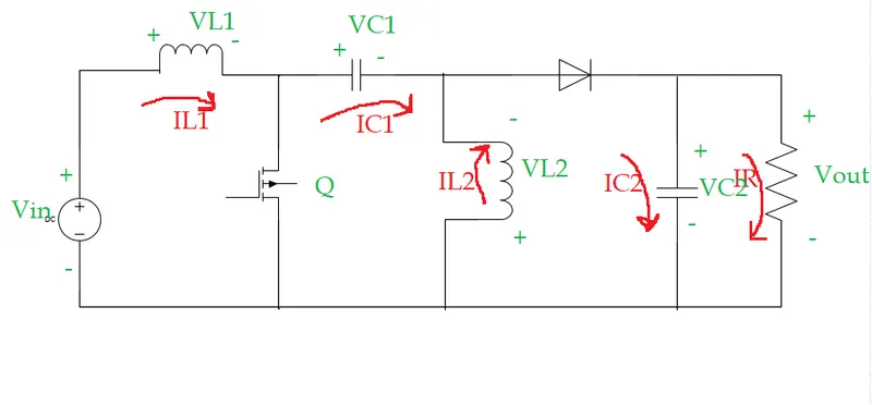
The SEPIC converter allows a range of dc voltage to beadjusted to maintain a constant voltage output.
For the SEPIC, when the pulse is high/the MOSFET is on, inductor 1 is charged by the input voltage and inductor 2 is charged by capacitor 1. The diode is off and theoutput is maintained by capacitor 2. When the pulse is low/the MOSFET is off, the inductors output through the diode to the load and the capacitors are charged. The greater the percentage of time (duty cycle) the pulse is low, the greater the output will be. This is because the longer the inductors charge, the greater their voltage will be. However, if the pulse lasts too long, the capacitors will not be able to charge and the converter will fail .
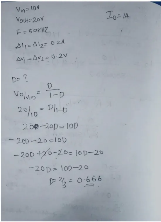
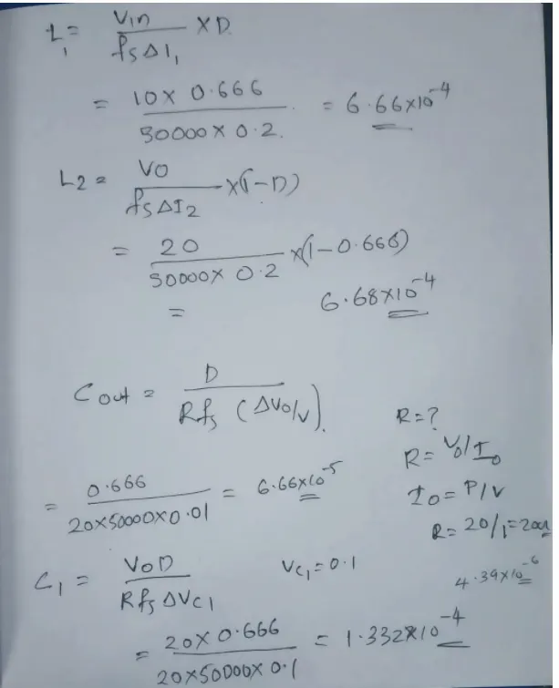
Calculation:-
Simulink model:-
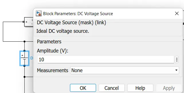
DC voltage
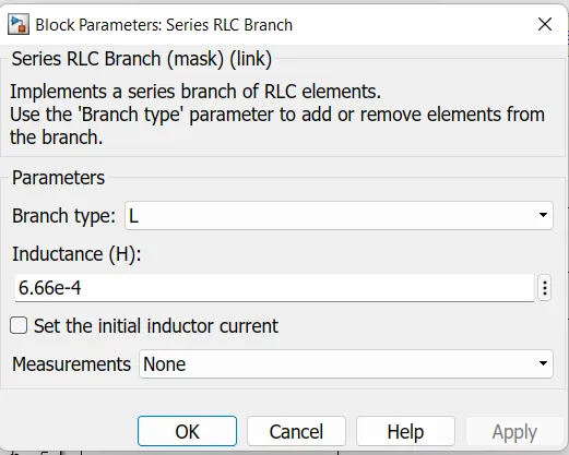
L1
L2
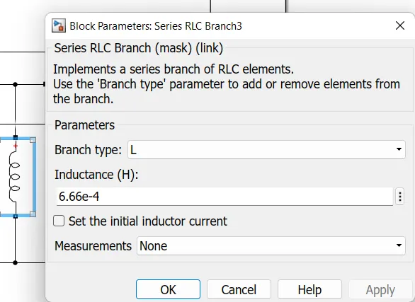
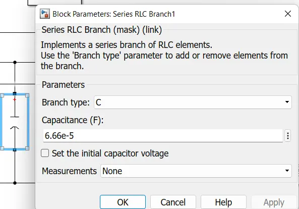
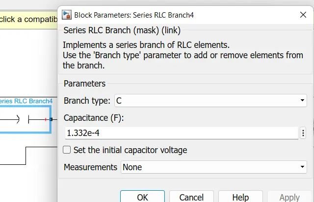
C1 and Cout
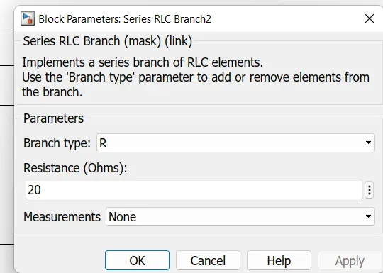
R
OUTPUT VOLTAGE
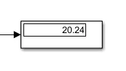
Results

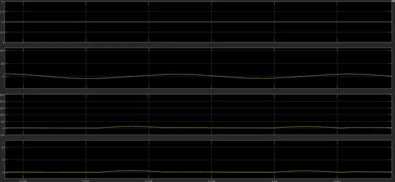
Mosfet current and voltage
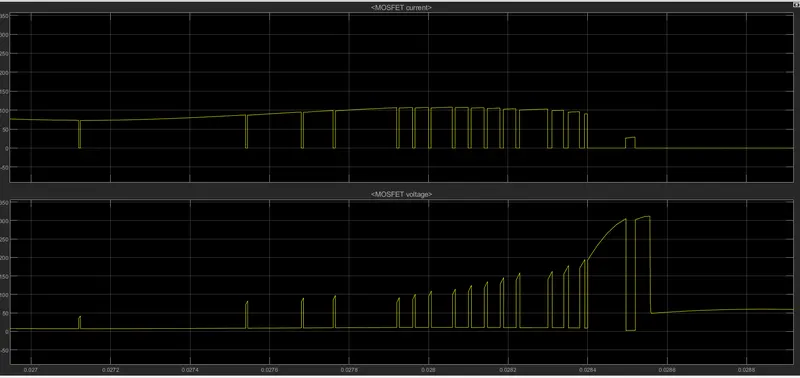
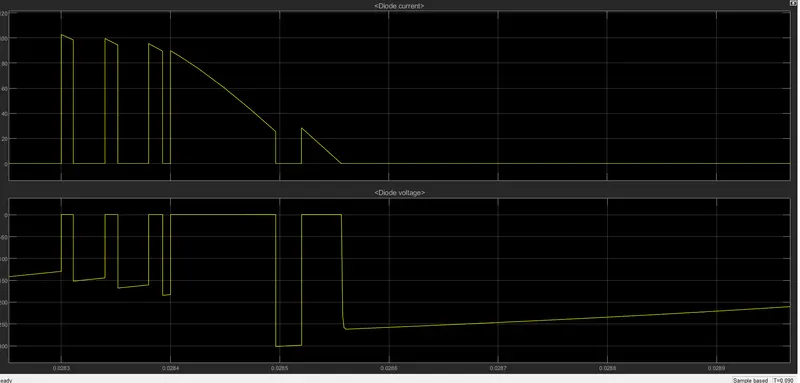
Diode voltage and current