PLANETARY GEAR TRAIN
AIM: To design a Planetary Gear Train using following inputs:-
MODULE = 2.5
INPUT SPEED OF THE GEAR = 200 rpm
NUMBER OF PLANET GEARS = 4
|
GEAR |
NUMBER OF TEETH |
|
RING GEAR |
46 |
|
SUN GEAR |
14 |
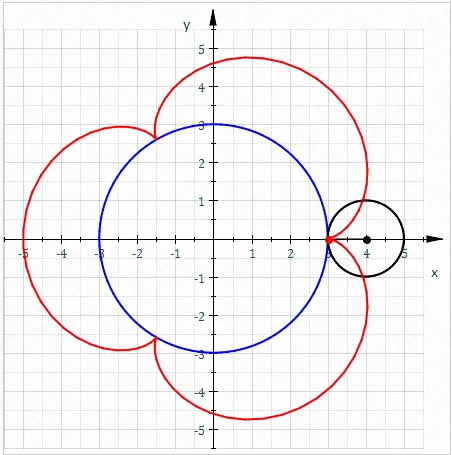
EPICYCLIC GEAR TRAIN: An Epicyclic gear train (also known as planetary gear) consists of two gears mounted so that the center of one gear revolves around the center of the other. A carrier connects the centers of the two gears and rotates to carry one gear, called the planet gear or planet pinion, around the other, called the sun gear or sun wheel. The planet and sun gears mesh so that their pitch circles roll without slip. A point on the pitch circle of planet gear traces an epicycloid curve. In this simplified case, the sun gear is fixed and the planetary gear(s) roll around the sun gear. An epicyclic gear train can be assembled so the planet gear rolls on the inside of the pitch circle of a fixed, outer gear ring, or ring gear, sometimes called an annular gear. In this case, the curve traced by a point on the pitch circle of the planet is a hypocycloid.
The combination of epicycle gear trains with a planet engaging both a sun gear and a ring gear is called a planetary gear train. In this case, the ring gear is usually fixed and the sun gear is driven.
EPICYCLOID: In geometry, an epicycloid or hypercycloid is a plane curve produced by tracing path of a chosen point on the circumference of a circle called an epicycle which rolls without slipping around a fixed circle.
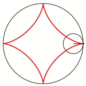
HYPOCYCLOID: In geometry, a hypocycloid is a special plane curve generated by the trace of a fixed point on a small circle that rolls within a larger circle. It is comparable to the cycloid but instead of the circle rolling along a line, it rolls within a circle.
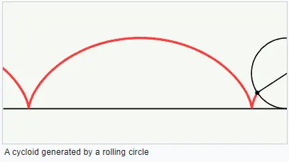
CYCLOID: In geometry, a cycloid is the curve traced by a point on a circle as it rolls along a straight line without slipping.
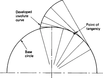
INVOLUTE: An involute (particular type of curve) of curve is the locus of a point on a piece of taut string as the string is either unwrapped from or wrapped around the curve.
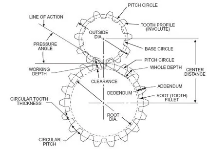
PITCH CIRCLE: It is an imaginary circle drawn in such a way that a pure rolling motion on this circle gives the motion which is exactly similar to the gear motion. These pitch circles always touch each other for the correct power transmission.
PRESSURE ANGLE: It is the angle between common normal at a point of contact at a pitch point. The standard values of pressure angle are 14.5⁰, 20⁰,25⁰.
MODULE: It is defined as the ratio of pitch circle diameter in mm to the number of teeth.
PROCEDURE:-
- Open design library and go to toolbox.
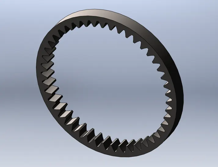
- Select ANSI metric. Go to transmission, select gears and drag ring gear to model workspace.
- Enter the required parameters like module (2.5 mm), face width (12 mm), outside diameter (130 mm) etc. Save the part.
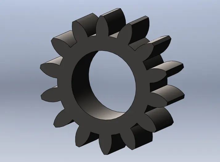
- Similarly select spur gear for sun gear and enter its parameters like nominal hole dia. 20 mm, face width 12 mm etc.
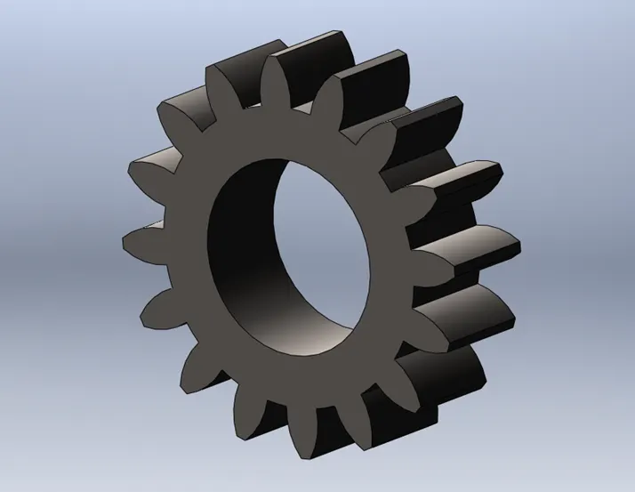
- Select spur gear again for planet gears and enter the number of teeth equal to 16. The number of teeth of planet gears can be calculated using pitch circle diameters of ring gear and sun gear and using formula of module m=D(mm)/T. The PCD of planet gear is 40 mm, nominal hole dia. Is 22 mm and the numbers of teeth are 16.
|
GEAR |
NUMBER OF TEETH |
PCD (mm) |
|
RING GEAR |
46 |
115 |
|
SUN GEAR |
14 |
35 |
|
PLANET GEARS |
16 |
40 |
- Design a carrier of planetary gear mechanism according to the nominal hole diameter of the sun and planet gears.
RING GEAR
SUN GEAR
PLANET GEAR
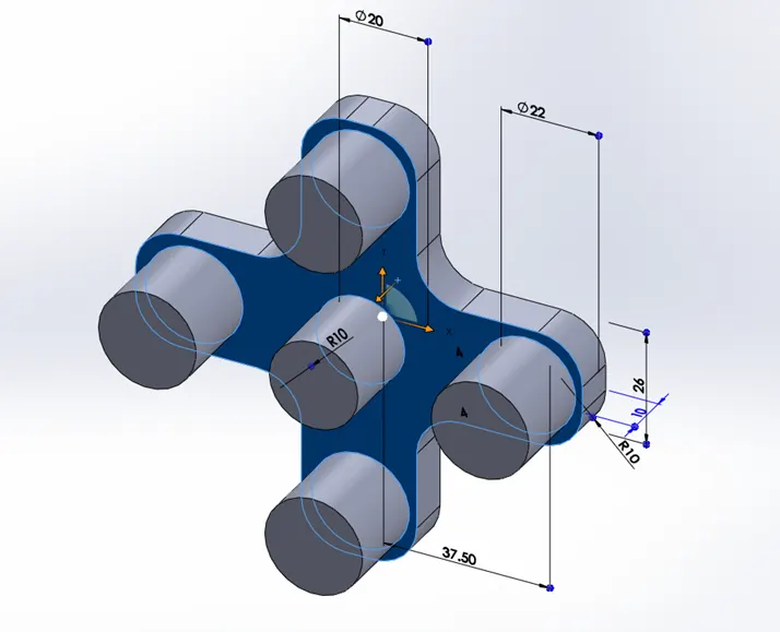
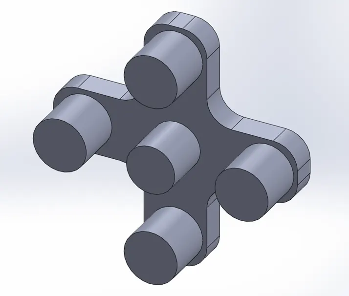
CARRIER
- Go to assembly to assemble the parts and to make a planetary gear mechanism.
- First of all coincide the origin of assembly and origin of carrier, and then make front plane of assembly and front plane of carrier coincident.
- Then insert spur gear and planet gear and make them first concentric to the shafts of carrier by selecting inside surface of gears and cylindrical surface of carrier. Add planet spur gear four times.
- Add ring gear to the assembly. Make the axis of sun gear and ring gear coincident and then make the surface front planar surface of ring gear and planet gear coincident. This completes the assembly.
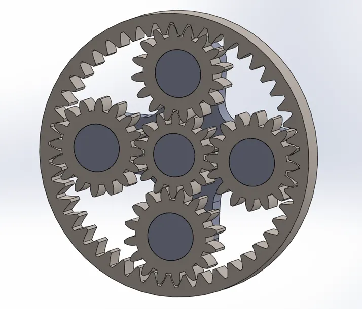
PLANETARY GEAR MECHANISM ASSEMBLY
- Go to motion analysis and fix the carrier so that there is no relative motion in the carrier when input is sun gear and output is in ring gear.
- Select the axis of sun gear for the motor.
- Select planet gears, sun gear and ring gear in contact surfaces. Select material, steel (dry) for all gears.
- Use 200 frames per second for the motion analysis.
- Go to graphs and select angular velocity for the output i.e. ring gear. Select the planar face of ring gear.
- Similarly set up motion analysis for ring gear and carrier by fixing sun gear, and by fixing ring gear when input is sun gear and output is carrier.
SIMULATION
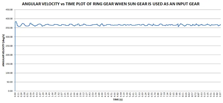
OBSERVATIONS: The above plot of angular velocity and time show that when the sun gear starts rotating and meshes with planet gears which in turn mesh with ring gear, the angular velocity of ring gear rises from zero to 378.16 deg/s at t=0.003 s. As the motion of gear mechanism progresses the angular velocity of gear mechanism rises, falls and remains between 350 deg/s to 400 deg/s. The maximum angular velocity attained by the ring gear is 382.69 deg/s at t=0.04 s and minimum angular velocity is 356.61 deg/s at 7.88 s.
SIMULATION
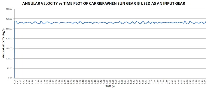
OBSERVATIONS: The above plot of angular velocity and time show that when the sun gear starts rotating and meshes with planet gears which rotate the carrier as the ring gear is fixed, there is rise in angular velocity of carrier from zero to 97.24 deg/s at t=0.001 s. The maximum angular velocity attained by the carrier is 287.82 deg/s at t=0.015 s. The maximum angular velocity attained by the carrier is 288.63 deg/s at 8.84 s and minimum angular velocity is 97.24 deg/s at 0.001 s.
SIMULATION
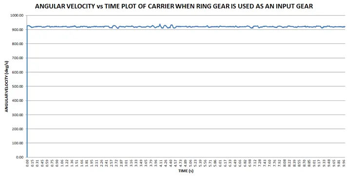
OBSERVATIONS: The above plot of angular velocity and time show that when ring gear starts rotating and meshes with the planet gears, the angular velocity rises to 924.65 deg/s at 0.005 s from zero angular velocity. The maximum angular velocity is 937.93 deg/s at 4.09 s and minimum angular velocity is 907.29 deg/s at 2.785 s.
CONCLUSION: The angular velocity of carrier is more (907.29 deg/s to 937.93 deg/s) when ring gear is used as an input gear as compared to the angular velocity of carrier when sun gear is used as an input gear (288.63 deg/s to 97.24 deg/s). There is a difference in angular velocities of ring gear and carrier when sun gear is used as an input gear in both the cases.
REFERENCES:-
WIKIPEDIA
GOOGLE IMAGES