Photo Realistic Rendering
Modeling of American Chopper in Solidworks
Objective:
The main objectives of this project are:
- To create individual parts of chopper using Solidworks
- To assemble all the individual parts into a chopper
- To know the application of decals, lights, cameras, etc.
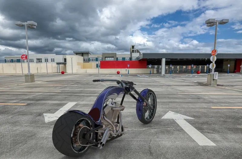
- To create the photorealistic model and render it using photo view 360 / Solidworks Visualize.
Introduction
This report contains a detailed part modeling, assembly, final rendering of a custom-designed American chopper in SOLIDWORKS. In part modeling, we first sketch the part/ component and create the 3D part using different features. Each part of assembly can be modeled separately and they can be assembled together with the application of mates in assembly.
Design methodology
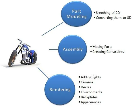
The following flowchart depicts the sequence of part modeling and assembly for American chopper in SOLIDWORKS:
Details of Features Used
A brief explanation of tools used in designing the Chopper Bike
Sketch
The sketch is used to create the 2D representation of the model. In Solidworks there are different entities are available as follows:
- Line
- Circle
- Arc
- Spline
- Rectangle
- Polygon
- Fillet
- Ellipse
2D Commands
1. Offset
The offset command create parallel line, curve, and concentric circles through a point or at a specified distance.
2. MirrorThe mirror is used to create the remaining half of a sketch/ copy of a selected sketch about a specified line.
3. Convert entity
It is used to project the last sketch into the current sketch plane.
4. Trim and extend entity
The trim command is used to remove the selected extra line/parts of an object. And the extend command is used to extend the selected boundaries or edges.
5. Linear sketch pattern
It is used to create multiple instances of features that can be uniformly be specified along one or two linear paths.
6. Dynamic mirror
Select the dynamic mirror feature to mirror pre-existing sketch. First select line, centerline, and linear model edge about which to mirror, and then create a sketch to mirror.Path - Tool> Sketch Tools>Dynamic Mirror
7. Smart dimension
It allows you to dimension the part which is created.
3D Commands
1. Extruded boss/base
It is used to convert the 2D sketch into a 3D model in one or both directions from the sketch plane. Here you have to specify direction up to the surface, vertex, value, body from the sketch plane.
2. Extrude cut
It helps to remove material from the created 3D model by using the 2D sketch. It is the opposite of extrude boss/bass feature. Here also you have to specify direction up to the surface, vertex, value, body from the sketch plane.
3. Revolved boss/base
It is used to revolve a 2D sketch (one or more profiles) along an axis, line, or centerline.
4. Revolved cut
This feature is just the opposite of revolve boss/base. The revolved cut allows to cut a profile around an axis, plane, and line to create complex geometry.
5. Swept Boss/Base
A swept feature is used to create a solid body by moving a closed entity/ profile along a specified sketch/path. In order to complete a feature, two sketches are necessary. One will be the closed profile and the second will be the path.
6. Swept Cut
A swept cut feature allows cutting a 3D model by sweeping a closed sketch profile along a specified path sketch. The path sketch will control the direction of the cut. Profile sketch should be connected to the path sketch.
7. Lofted boss/base
The loft feature creates a solid body by making transitions between multiple profiles and guide curves. It helps to generate complex geometry in one feature.
8. Lofted cut
The loft cut is allowed to remove the material between two sketch profiles. Make sure that selections are must under the profile selection box and not the guide curve selection box
9. Fillet
It is used to create a rounded shape at the internal or external faces of the part. There are different types of fillet:
- Constant Size fillet
- Multiple radius fillet
- Round corner fillet
- Setback fillet
- Variable size fillet
- Face fillet
- Full round fillet
- Asymmetric fillet
10. Chamfer
This feature creates a cut on a selected edge, face, or vertex. Types of chamfer:-
- Angle –Distance- Enter the values of distance and angle in the chamfer parameter box.
- Distance- Distance- Enter the values for both distances in the chamfer parameter box or on the side of selected edges.
- A vertex- Enter values for the three distances on each side of the selected vertex
11. Patterns
- Linear pattern – To create multiple instances of one or more features that can be space uniformly along a specified path, plane.
- Circular pattern – To create multiple instances of one or more features that can space uniformly along an axis, line.
- Curve Driven Pattern – To Curve creates multiple instances of one or more features that can be spaced uniformly along the 3D curve (open or closed curve).
12. Shell
It is used to define the thickness of the wall, hollows out a part, leaves open the selected faces. Shell may be with uniform or multiple thickness faces.
13. Dome
A dome is a curved formation or structure. It is shaped like half of a sphere. Select one or more planar or non-planar faces. This allows you to apply domes to irregularly shaped contours.
- Face to the dome - Used to apply dome to faces whose centroid lies outside the face.
- Elliptical Dome -Used to apply dome for cylindrical/ conical model.
Path- Insert>Feature>Dome
14. Split
The split feature is used to create multiple bodies or surfaces from one part/ surface. In the trim toolbox, we need to select sketch and click on the cut part. In this feature, we can create multiple bodies or consume cut bodies.
Path- Insert>Feature>Split
15.Combine
There are three different options are available to use the combine feature.
- Add- To merge multiple bodies together into one.
- Subtract- To remove multiple bodies from the main body.
- Common- To add two bodies together and keep the area that is common to them.
Path- Insert>Feature>Combine
Surface Modelling Features :
Surface modeling is used to build out a representative of solid objects exterior and its contours. Following features are used in the design of the seat, gas tank of the chopper.
1. Swept Surface
The surface is created by sweep profile and sweep path.
2. Surface Trim
It is used to cut away material from a surface.
3. Boundary Surface
The boundary surface creates surfaces that can be tangent or curvature continuous in both directions. In most cases, we get high-quality results as compare to lofted surfaces.
4. Surface Knit
The surface knit feature combines multiple faces and surfaces into one. Surface edges must be adjacent and not overlapping.
5. Lofted Surface
The surfaces are generated by multiple 3D curves / existing edges. There should be a tangency between the selected curve/edges.
6. Extend Surface
This feature extends the surface by selecting an edge, multiple edges, or a face.
7. Filled Surface
The feature creates a surface to fill the gap in a model.
Appearance
An appearance defines the visual properties of the model which include color and texture. We can apply appearance to the individual to the complete model/one or more face /edges. It does not affect the physical property which is defined by material.
TRANSMISSION BELT
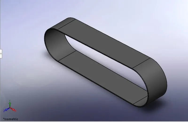
The transmission belt is used to transfer the power from engine to gearbox and designed through the following features
- Sketch
- Offset
- Extrude
- Fillet
PROCEDURE
- The front plane was used to create the sketch for the transmission belt.
- Using line command a horizontal line is drawn from the origin to the right and an arc, tangent to the line drawn was sketched continuously.
- From the end of the first arc, another line was drawn horizontally towards the left.
- Another arc was drawn to connect both the horizontal lines.
- The connecting points of the arcs are made to be tangent to the horizontal lines.
- The starting point was made to be coincident with the origin and the required dimensions were applied using Smart dimensions tool.
- Now the sketch was fully defined and then offset the sketch inwards in such a way that it creates a thickness for the transmission belt.
- Then the sketch was extruded from the sketch plane using the blind option and the required fillets were added along the edges of the belt on both sides.
- Now the part was saved by adding the matte rubber appearance.
KICKSTAND
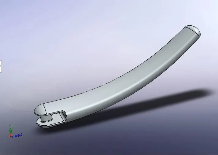
The kickstand is used to support the Chopper and designed through the following features
- Loft
- Dome
- Extrude Boss
- Extrude Cut
- Split
- Fillet
PROCEDURE
- An ellipse was sketched on the front plane and made its center point coincident with the origin.
- Then a spline was created from the origin on the Mid Plane and applied the required dimensions.
- A new plane was generated normal to the spline using a plane tool from reference geometry.
- Using the reference plane another ellipse was sketched and its center point must be made pierced with the endpoint of the spline.
- Then by using the Lofted Boss/Base tool a loft was created between the two ellipses and then it was made to align with the spline using centerline parameters.
- Then two domes were created on either side of the lofted model by using the dome feature for the required dimensions.
- Now on the bottom right side, a rectangular extruded cut was made on the midplane using Extruded Cut with Through All-Both option for making a clamping socket.
- Then a circular holder was extruded in between the clamping socket by sketching a circle on the top plane.
- Then a small portion of the part from the lower side of the kickstand has been split away using the split tool for having a perfect ground clearance.
- Finally, the part was saved by adding the fillets for the required edges and applying the chrome appearance.
Front Fender
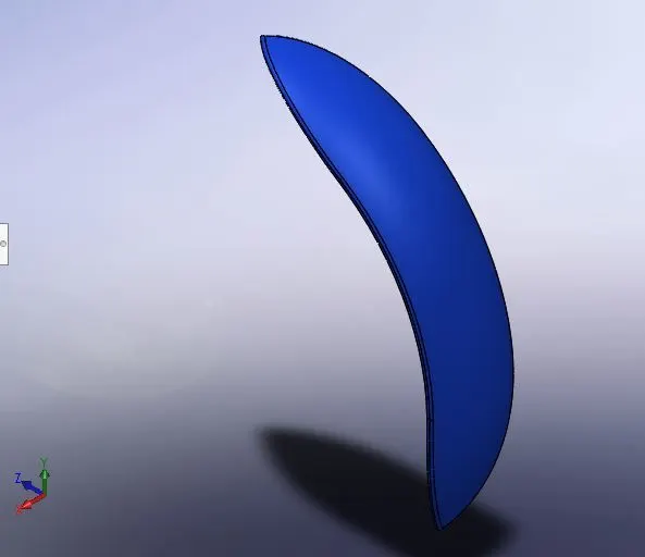
The front fender is used to protect the front wheel from foreign particles and dust which is mointed above the wheel in the fork.
Features Involved
- Sketch
- Offset Entities
- Trim Entities
- Revolve
- Split
PROCEDURE
- For modeling the Front Fender the required sketch was drawn on the front plane and revolved using Revolved Boss/Base.
- Then by using the Split option the unwanted portion has been removed and then the fillets were added around the edges to get a smooth edge for the fender.
- A Shell was created on the inside face of the fender.
- Now the part was saved by adding an appropriate appearance.
REAR FENDER
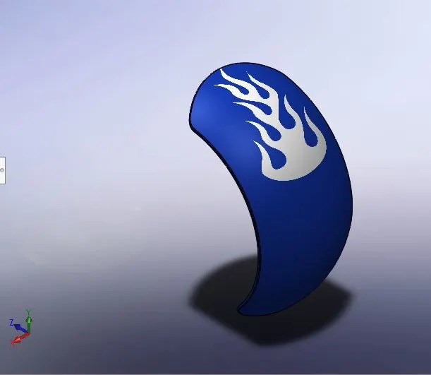
The Rear Fender is mounted above the Rear Wheel and has customized paintings based on the theme of the chopper.
Features Involved
- Sketch
- Offset Entities
- Trim Entities
- Revolve Extrude
- Split
PROCEDURE
- A 3 Point Arc was sketched on the front plane and applied the required dimensions using the Smart Dimensions tool.
- Then offset the arc towards inward using the Offset Entities tool and join the two arcs by sketching a line on both sides.
- Then a construction line was drawn horizontally from the origin and the required sketch relations were added for creating a revolve using Revolved Boss/Base.
- Now for giving a smooth edge for our fender a curve was drawn on the top plane and split the portion which was not required.
- Then a shell was created on the inside face of the fender and the fillets were added throughout the edges.
- Now the part was saved by applying an appropriate appearance.
OIL TANK
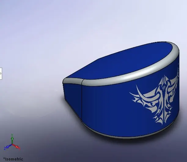
Oil Tank is Hollow Solid Model created using following features
- Boss Extrude
- Combine
- Fillet
- Shell
PROCEDURE
- First, a horizontal construction line from the original was drawn on the top plane then a midpoint line was drawn vertically connecting the construction line on the left side.
- Then two lines from either end of the vertical line were drawn with required sketch relations. Then the lines were connected by drawing a 3-Point Arc which is tangent to that line
- Now the fully defined sketch was extruded and another sketch was drawn on the front plane and extruded.
- Now the Combine option is used to combine both the extruded parts with the common operation type and a shell was created using the Shell feature.
- Finally, the part was saved by adding the proper fillets along the edges and applying an appropriate appearance.
CHAIN
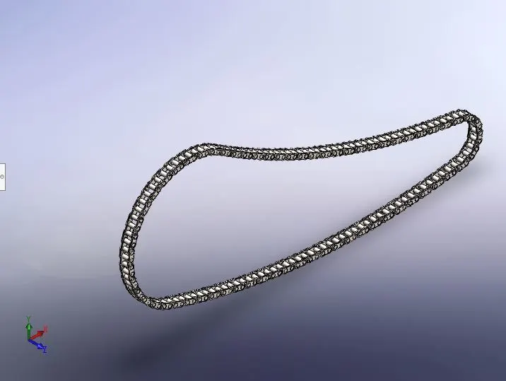
This model is approached through creating Sketch blocks and Linear Pattern and mirrored along the Frontplane
Features Used:
- Sketch Blocks
- Extrude
- Curve Driven Pattern
- Mirror
PROCEDURE
- For modeling the chain first a pathway for the chain was created using arc command.
- Then the outside chain link and the inside chain link have been sketched on the midplane using the circle, line, and arc commands and saved it as blocks.
- Then both the links were extruded to the midplane by using the insert block command and Extruded Boss/Base.
- Now the pins were created and the fillets were applied as required.
- Then by using the Curve Driven Pattern copy the chain links and pins along with the pathway we created for the chain.
- Now the chain links are mirrored parallel to the current links of the chain using the Mirror command.
- Now the part file was saved by adding proper fillets as required and applying the chrome appearance.
PEDAL
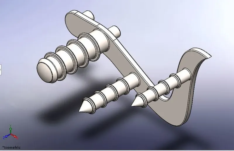
The Pedal model is mounted external to the chassis on both sides which provides a footrest to the riders and is designed through the following features
- Extrude
- Fillet
- LinearPattern
PROCEDURE
- First, the required sketch to model the pedal has been drawn and dimensioned it using Lines, Arcs, and Splines.
- Then the footrest part was sketched and extruded using Extruded Boss/Base and applied the proper fillets.
- Now using construction line and normal line the required sketch was drawn on the top plane and then the sketch was revolved with respect to the construction line.
- Now the dome has been created over the face of the footrest.
- Then the circular extrude was created using Offset, Fillet, Chamfer, and Linear Pattern options.
- Finally, the part was saved by adding Chrome appearance
REAR-WHEEL
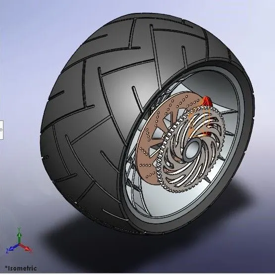
Rear Wheel are broad and are one of the most customed made components in the chopper and has various rim styles but the chopper is famous for its spider-webbed design with its chromium alloy
Features Used
- Revolve
- Extrude
- Cut Extrude
- Cut Revolve
- Combine
- Circular Pattern
- Fillet
- Chamfer
Procedure
- First, the Rim was designed by creating the required sketch on the front plane and applying proper dimensions using Smart Dimensions.
- The created sketch was used to create a revolve using Revolved Boss Base and Circular Pattern options.
- The Rim has been designed to have a spider web-shaped rim wheel.
- Proper fillets were added and applied the chrome appearance.
- Now the Rotor has been designed by sketching two circles on the right plane.
- The first circle was used to create a hub for the wheel using Extruded Cut option.
- By using the Linear Sketch Pattern sketch four circles sideways on the rotor and use Extruded Cut.
- By using Circular Pattern the holes on the Rotor for the required no of instances has been created.
- Now for designing the Caliper the required sketch was drawn and extruded using the Arc, Trim Entities, and Extruded Boss/Base command.
- Then the Chamfer has been applied for the required dimensions and gave the required appearance.
- Now the Sketch for the Sprocket is drawn on the right plane and extruded. For creating the gear teeth around the sprocket Circular Pattern was used and proper fillets were added for the edges to get a smooth edge on the teeth.
- Finally, the Tire has been designed by drawing the required sketch on the front plane and revolved around the rim.
- To create a grip on the wheels the tire should have some cut extrudes over the tire which was created using Circular Pattern, Extruded Cut, and Fillets. Now complete the design by applying Matte Rubber appearance.
FRONT WHEEL
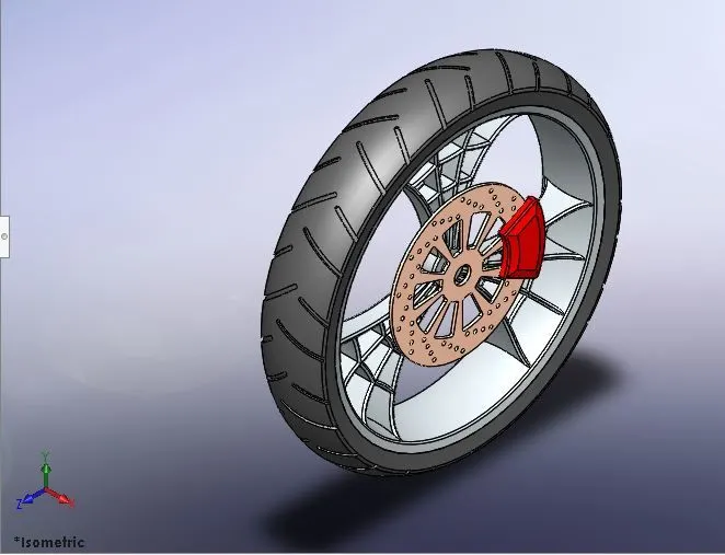
Front Wheel is designed the same way as Rear Wheel and attached to the front fork with a fixed rotation along the fork to allow the chopper to make turns. The Wheel rim also has a spider web shaped and has a matte rubber tire with a Profile cutout to provide friction between the tyre and the road.
FRONT FORK
Features
- Revolve
- Boss Extrude
- Linear Pattern
- Cut Extrude
- Dome
- Cut Revolve
- Sweep
- Combine
- Mirror
- Fillet
- Projected Curve
Procedure
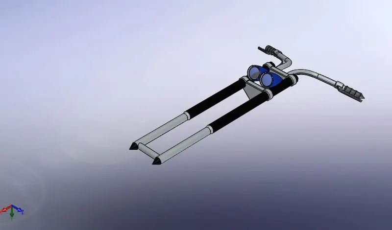
- To design the Front Fork half side of the fork has been created and the remaining half was mirrored using the first half.
- Hence the first half of the fork has been sketched on the front plane and revolved using Revolved Boss/Base.
- The crown part of the fork was designed using the Extruded Boss/Base and the base crown was created using Linear Pattern and the crowns were connected by using extrude thin feature.
- The Through-Axle was used to hold the Front Wheel and it was also created using Extruded Boss/Base.
- For creating the headlights the required sketch was drawn on the front plane and revolved using Revolved Boss/Base.
- For creating the glass face on the headlight Dome and Extruded Cut feature was used and applied the required fillet.
- The Cut Revolve and Body Move options were used to get the headlight to look realistic and for positioning perfectly.
- Project Curve and Swept Boss/Base tools were used to create the handlebars and brake wires.
- For creating the handles a new plane was created using the reference geometry plane command on the handlebar and revolved using Revolved Boss/Base.
- For creating the brake Extruded boss/Base were used and proper fillets were added.
- Then the other half of the handlebars were created using the Mirror command and then the forks and handlebars were combined separately with the other half using the Combine command.
- Now the part was saved by applying Matte Rubber appearance to the handles and brake wires and Chrome appearance for forks and handlebars.
CHASSIS
This is the base of the chopper and Carries various components like the Engine. This model is approached by creating multiple spline entities and combining them to a composite curve.
Features used
- Offset Entities
- Convert Entities
- Project Curve
- Trim
- Sweep Bose
- Split
- Revolve
- Extrude Cut
- Extrude Boss
- Fillet
- Combine
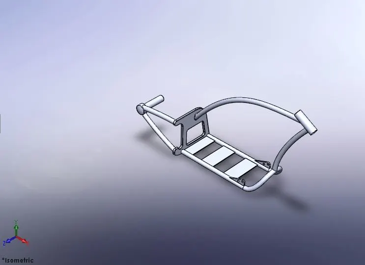
The Chasis has Four Parts
- Top Frame
- Axle Housing
- Base Frame
- End Frame Shaft
PROCEDURE
- First, the blueprint was added using the insert sketch pictures option on the midplane. The blueprint was used to structure the sketch of the Frame.
- The Bottom Rails for placing the engine were created by drawing a projected curve and the curve was swept using Swept Boss/Base and the other half was mirrored.
- The Back Frame was created using Extrude Boss/Base and Revolved Cut. Finally, the required chamfer and fillets were added.
- The Bottom Tail Tube was created using Swept Boss/Base and Extruded Boss/Base. The dome option was used to create a dome on the front face of the Hub.
- For creating the Steer tube Extruded Boss/Base and Extruded Cut were used.
- For creating the Foot Pedal Mounts Extruded Boss/Base, Extrude Cut, Mirror and Fillet were used.
- Split and Combine options were used to group the separate parts of the Frame.
- Finally, the part was saved by adding the black painted appearance.
ENGINE
Chopper Engine is designed using series of Projected Curves and Composite Curves. This complex Solidmodel has the following parts
- Cooling Fins
- Exhaust Pipe
- Gear Box
- Sprocket for Chain Transmission
- Engine Case
- Spark Plugs
Features Used
- Extrude
- Extrude Cut
- Thin Extrude
- Chamfer
- Project Curve
- Linear Pattern
- Circular Pattern
- Revolve
- Mirror
- Dome
- Sweep
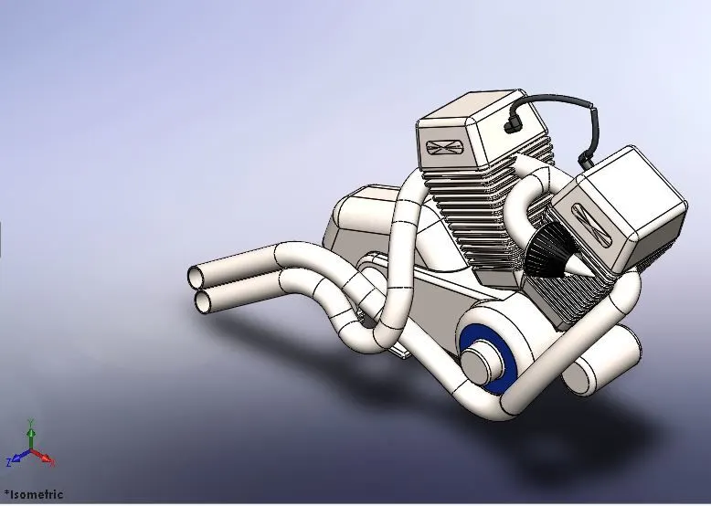
PROCEDURE
- The Blueprint of the sketch was added using the insert sketch pictures option on the front plane.
- By using the blueprint the required sketch was drawn and extruded using Extruded Boss/Base and proper fillets were applied.
- Then a plane was created using Reference Geometry and the transmission system was created for placing the Transmission belt using Revolved Boss/Base, Extruded Boss/Base, Extruded Cut, Chamfer, and Circular Pattern. Then the fillets and dome were applied to the required area.
- For creating the cylinders of the engine the Extruded Boss/Base was used and the dome feature was used to create the dome on either side of the cylinder.
- For creating the cooling fins Linear Pattern was used and the other half was mirrored along with the fins and domes.
- The Air Inlet Ducts were designed using Circular Pattern, Extruded Cut, and Revolved Boss/Base.
- For creating the Exhaust Pipes Composite Curve feature were used on the reference plane needs to be created on the face of the engine cylinder.
- By using Swept Boss/Base the exhaust pipes were created and finally, the Split option was used to cut the unwanted part.
- Then the Spark Plugs were made using Extruded Boss/Base and Swept Boss/Base.
- Finally, the part was saved by adding appropriate appearances.
GAS TANK
The Gas Tank is approached using Surface Modelling Features and converted to a rigid solid body after enclosing as a closed surface model. The Gas tank provides the Seating grip for the Rider and looks stunning with different themes and sketches with different choppers. The main purpose is to store the Fuel and hence the solid body is shelled to the appropriate thickness
Features Used
- Surface Sweep
- Surface Trim
- Surface Loft
- Boundary Surface
- Surface Knit
- Sweep cut
- Fillet
- Mirror
- Shell
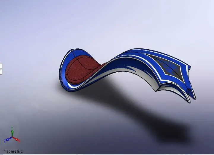
PROCEDURE
- First, the underlay image of the chopper was added using insert sketch pictures.
- Then a plane was created with respect to the front plane and a sketch was drawn and swept using the Swept surface feature and by using the Surface Trim tool the required shape of the Fuel Tank was achieved.
- Then by creating another plane a projected curve was drawn and then by using the curve the surface loft was created using the Lofted Surface tool.
- One more plane was created and another curve was projected and Boundary Surface tools were used to create a surface of the fuel tank.
- The other half was mirrored and both the halves were joined at an edge by using the Knit Surface tool.
- Then Split Line was used to creating the sketch for the seat and the Surface Extrude option was used to create the solid body of the seat. Proper fillets were added to get smooth edges for the seat.
- For placing the fuel tank over the top tube of the Frame a tube-shaped portion was removed using Boundary Surface, Lofted Surface, Knit Surface, and Swept Cut tools.
- Finally, the proper fillets were added along the edges of the fuel tank and a shell was created inside the fuel tank using the Shell command.
- By applying an appropriate appearance the part was saved.
The Decals are added to the tank using Photoview 360 and appearances are given as Glossy Blue car pain for the main body.
ASSEMBLY
Chassis is the first component inserted into the assembly model and fixed with respect to the three planes.
Based on Chassis all other models are assembled using appropriate mates to fully define the assembly.
PROCEDURE
- The engine is placed on the bottom of the chassis.
- The pedal is attached to the side of the chassis and the component is mirrored to the other side
- The kickstand is attached to the left bottom side of the chassis
- The transmission belt is fixed between the two gear drives and the ensured that teeth mesh properly
- Oil Tank is placed above the Engine Casing
- Rear Wheel is attached to the End frame of the Chassis and the Rear Fender is placed using appropriate concentric mates
- The chain is Inserted between the rear wheel sprocket and Engine Sprocket.
- The Gas Tank is placed over the Top Frame.
- The Front Axle is attached to the front shaft of the chassis.
- Finally, the Front Wheel and Front fender are attached to the axle
- The Axle, Front Wheel, and Fender are given an angular mate to move on both sides.
The Kickstand, Front Wheel, and Rear Wheel are grounded to the Plane to create a realistic model view.
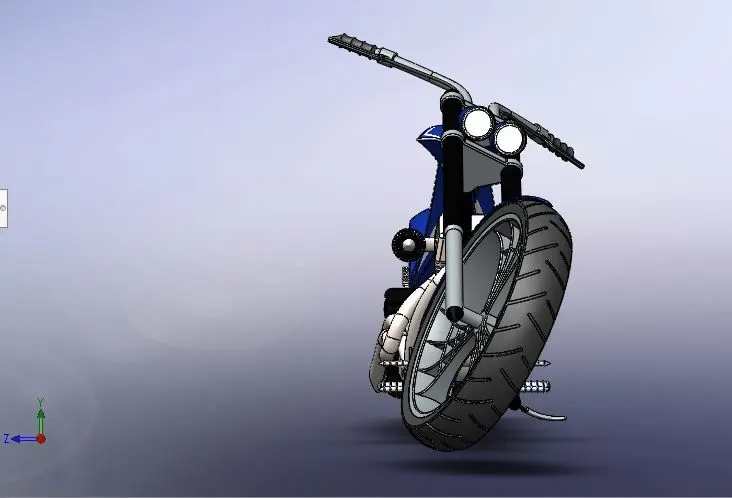
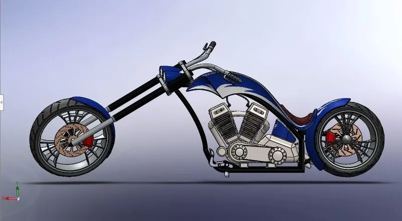
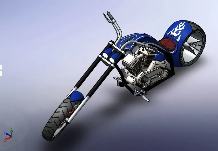
Here are some screenshots of the overall assembled American Chopper from different views.
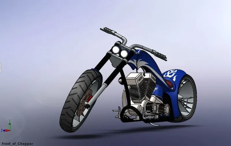
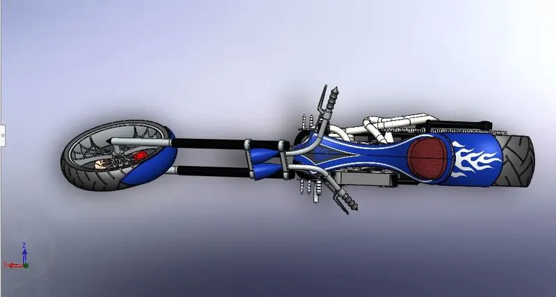
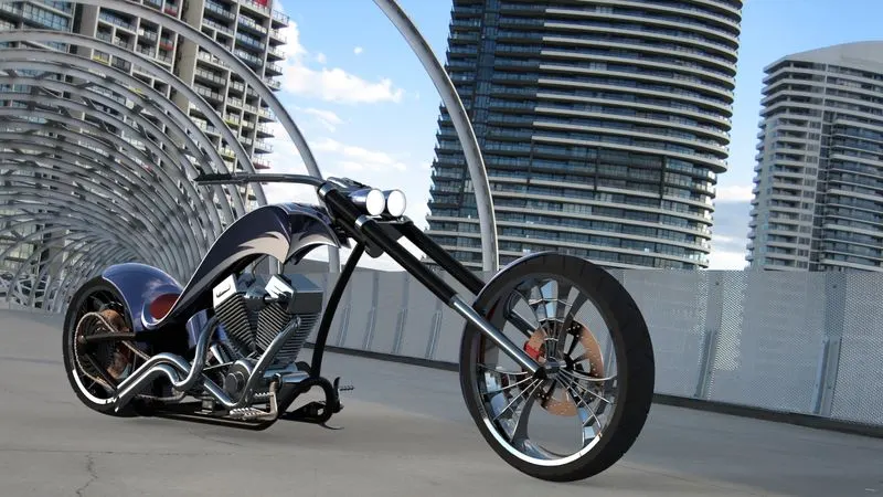
Final Rendered Image using Solidworks Visualize
Conclusion
Thus the project Design and Assembly of American Chopper Bike with photo-realistic rendering using SOLIDWORKS has been created and completed successfully.