Door Arm Rest Week 8 Challenge
Objective: Creation of Door Arm Rest and making it into a solid part according to OEM Standards
Methodology
1. Create the Tooling Axis
2. Check the Draft Analysis For Class A given
3. Creat Class B Surface
4. Create the Class C Surface
5. Make it into a solid part
6. Check the draft analysis
As the given model is having too many complex surfaces it won't get clear with one tooling axis to clear the whole model we need a Side Core/Lifter Tooling Axis
Creation of Main Tooling Axis
- Using Circle/Sphere/Ellipse Center Created a point in the center of Class A
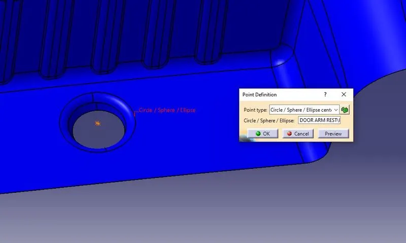
- Then Using Line Command With Point and Direction Created a line Perpendicular to class A and did the draft analysis for class A by moving the compass around the tooling axis created
- After checking the position where it is getting cleared, I locked the compass position and changed the tooling axis in the same direction by giving the direction as the compass position.
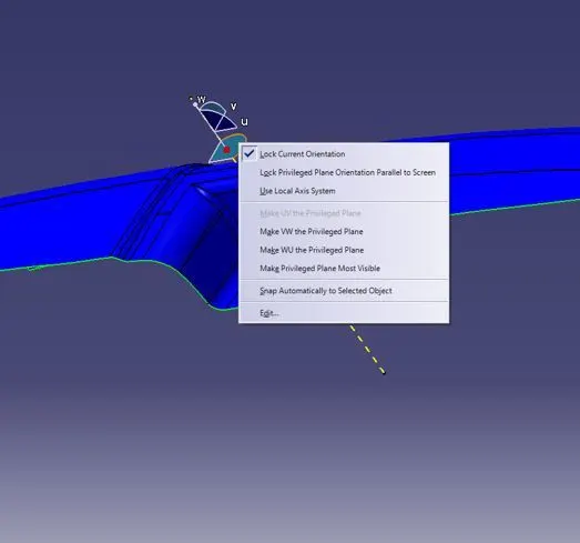
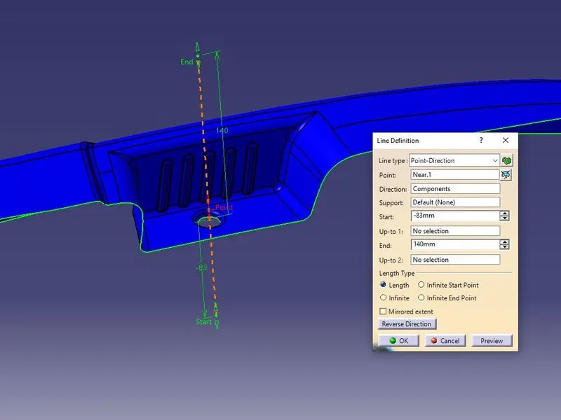
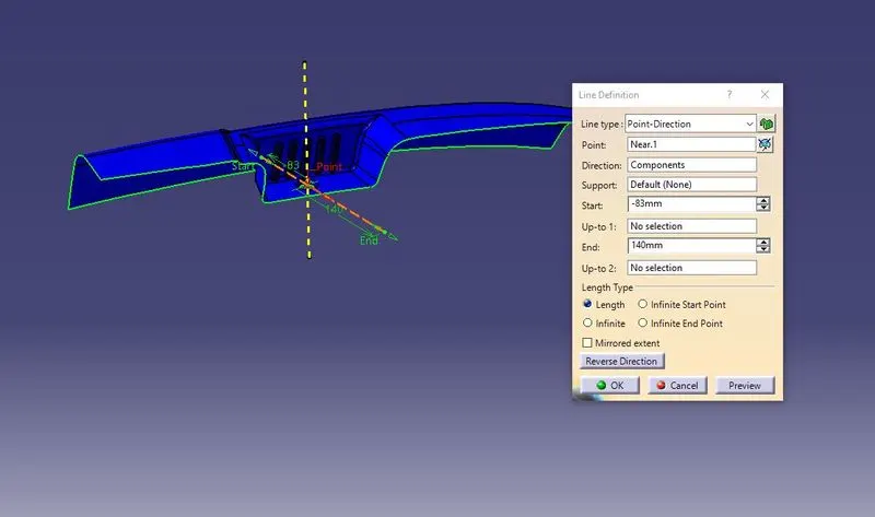
Now to clear the remaining part of the Arm Rest, I made a Lifter Axis using the same Procedure point and Direction Direction as the Compass where it can clear the Draft.
Creation of B Surface
- From the given Class A I took an Offset of the required Nominal thickness as the offset value.
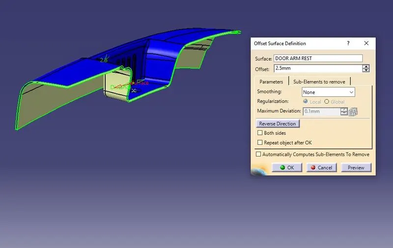
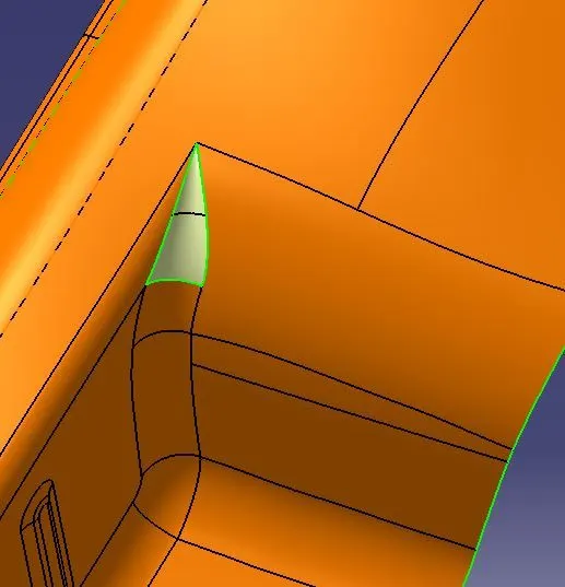
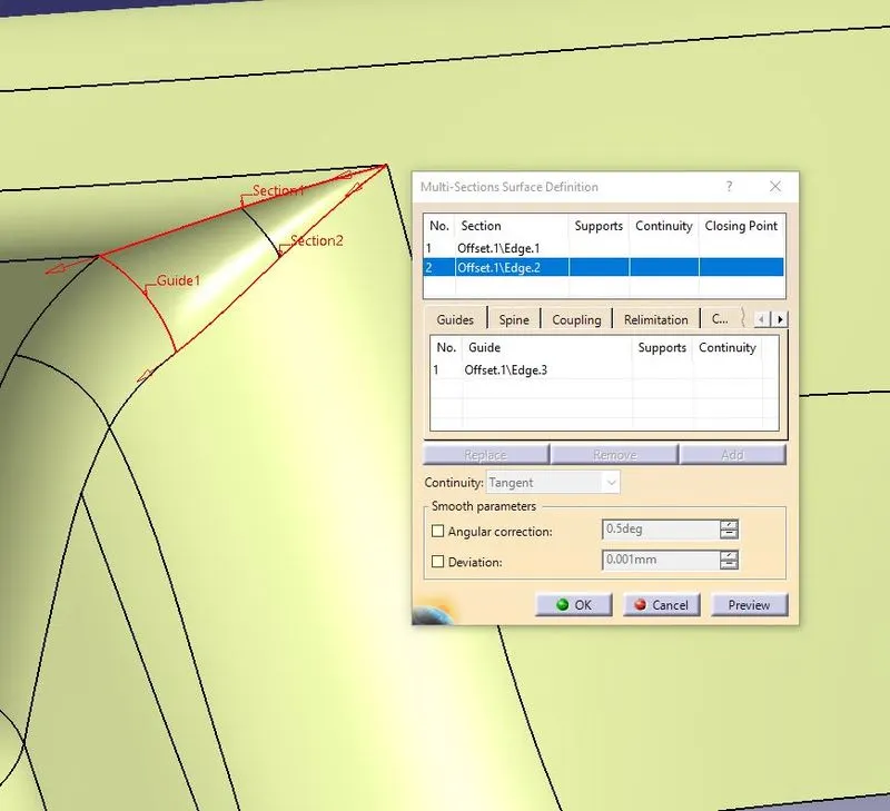
- As the Component is having some Complex fillets in some places it cannot be offsetted to overcome those sub-elements I used Muti Section Surface and solved them.
Class C Creation
- To Create Class C I took all the Class A boundary edges as the Reference for the sweeps
- By extracting the edges of class A I got the Guide curve for the Reference with Surface Sweep
- Reference Surface will be my Class A
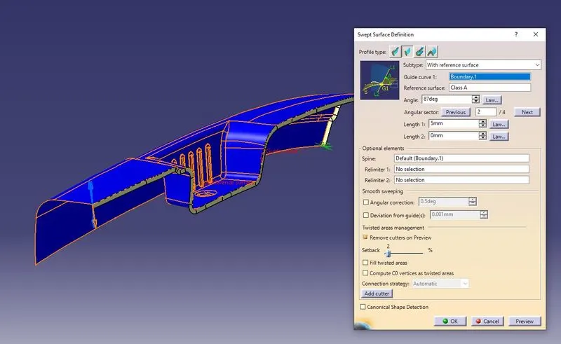
- After Creating All the sweeps around. Extrapolate the corners where it is not getting joined and trim them to get the final C Surface output
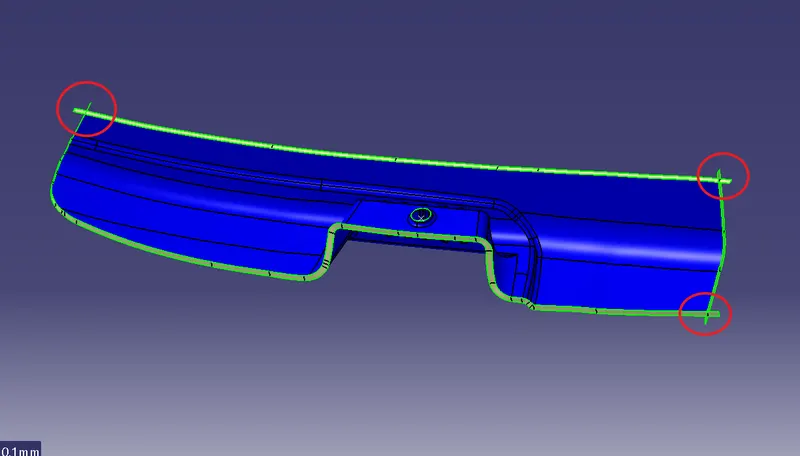
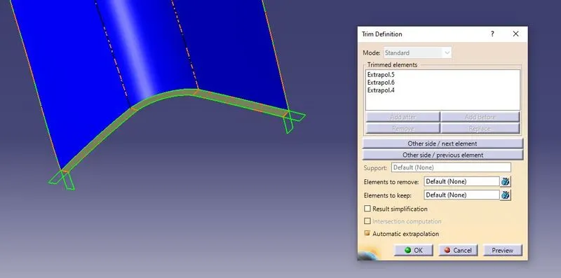
- Now we got the C Surface, To make it into a solid part we need to join all the A, B & C
- Before going to make it solid I Extrapolated the B Surface with a value of 5 mm which allows me to trim with the C Surface.
-
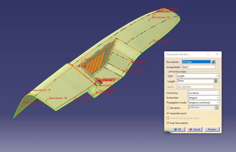
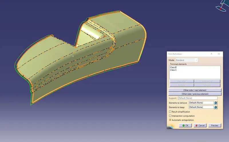
- As there is a hole-like feature in the center of the armrest for some attachments which also needs to be closed. To close that I just extrapolated the boundary of the class A Hole to some extent which will cross the offset.
- Then by giving a sweep of 75deg of the B surface I trimmed the unwanted surface.
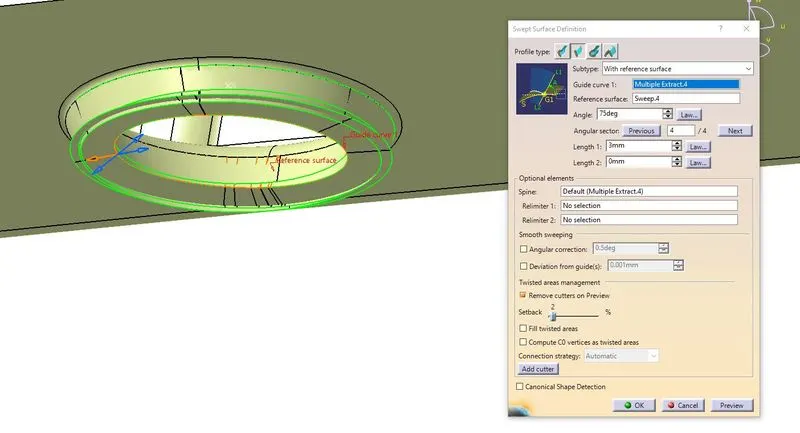
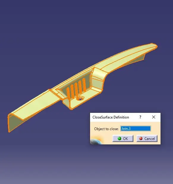
- Now We can proceed to join all the Surfaces (A, B & C) using Join Command
- Then by inserting a new part make this Close Surface into a Solid part.
Draft Analysis
- To perform the draft analysis the view parameters are first set to material mode.
- Then go to Insert >>analysis>>feature draft analysis.
- First, select the axis system and drag the axis system to align and coincide with the tooling axis and lock the orientation. This axis system defines the draft direction according to the tooling axis.
- Switch on the color scale and set the minimum draft value. Here it is set to 3 degrees and it will be displayed in green color. Any draft angle below 3 degrees will be shown in red color.
- Here, the compass direction is rotated to have the positive direction in a maximum portion of the part. Then the compass is locked in the orientation and a new tooling axis is created using the compass as the direction.
- Using the Main Tooling Axis it cleared 80% of the component with an Angle of 2.9/3 deg
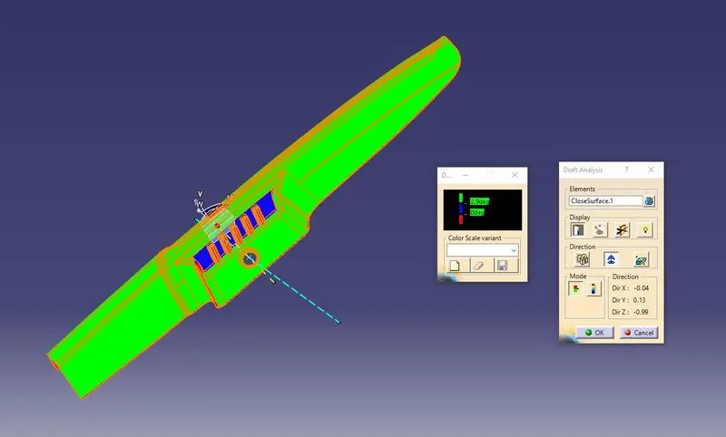
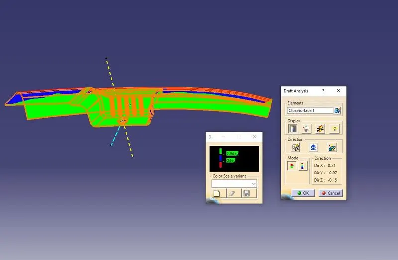
- The remaining 20% which is not cleared is made clear with the Side-core/Lifter tooling axis.
-
Conclusion
Hereby I can Conclude that the given Armrest is designed according to the OEM standards with the thickness of 2.5 and draft analysis is also cleared using the tooling axes created.