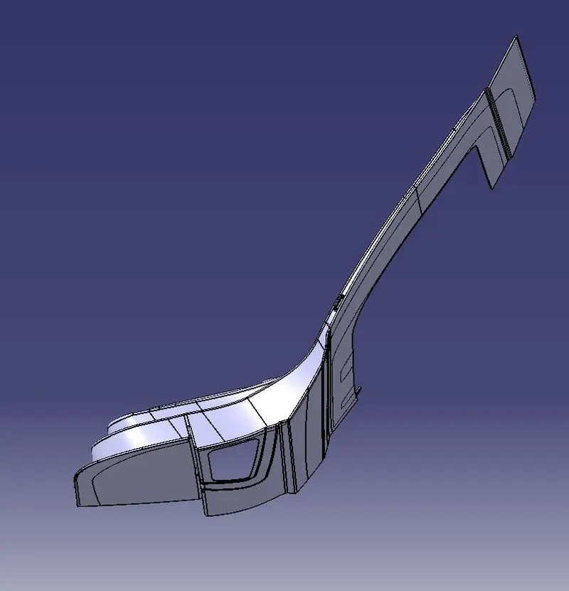
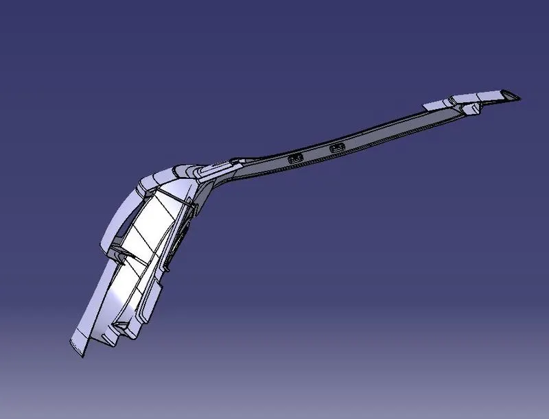
Design of backdoor
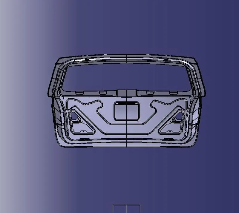
Objective: Design an Automotive Back door (or) Boot door using the Class A styling surface with appropriate design methodologies, and provide the necessary reinforcement and embosses for it.
Introduction:
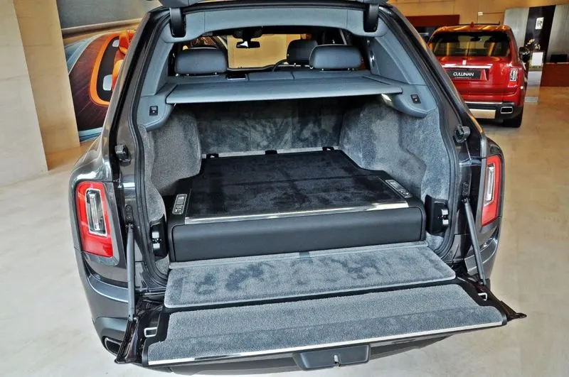
The Back Door of a car is the rearmost part of the vehicle which gives access to the trunk space of the vehicle. The rear door also supports the reinforcements and added weights of the Wiper Motor, Gas Stay, Tail Lamp, and Latch and Striker.
The Backdoor/tailgate is one of the closure commodities in BIW sheet metal design. The backdoor has a lot of components inside and is designed to corporate them easily. It affects the rear visibility and luggage area.
In this project, I have designed a back door for a hatchback car where it is hinged at roof level. Similar to the hood and side doors, the backdoor is a swinging/closure commodity in a car. It consists of an outer and inner panel. It is a very critical component because of the passenger safety requirements.
The Backdoor has to be designed by keeping in mind the space required for the luggage compartment as well as to accommodate the Latch and Striker motor and Wiper motor without compromising the strength of the component.
Usually, Aluminum or Steel is used to manufacture the backdoor. While Aluminum backdoor is lighter in weight and has a lesser number of components (since the part is "cast", it has a varying thickness and therefore doesn't require reinforcements). Steel backdoor is "deep drawn" with uniform thickness, added reinforcements, and therefore is heavier. But the production n cost of the latter is lesser and therefore a Steel backdoor is priced lower.
- Rear Visibility.
- Support structures like hinges and gas stay.
- Mounts for wiper motor, tail lamps, and other wiring loops.
- Fit and clearances.
- Boot space
- Rear crash regulations and requirements.
- Sealing and its functions.
- Joining techniques like hemming, spot welding, Mastic Sealent, etc.
Components of Backdoor
- Inner panel
- Outer panel upper
- Outer panel lower
- Hinge reinforcement LH
- Hinge reinforcement RH
- Gas stays reinforcement LH
- Gas stays reinforcement RH
- Wiper motor reinforcement
- Latch reinforcement
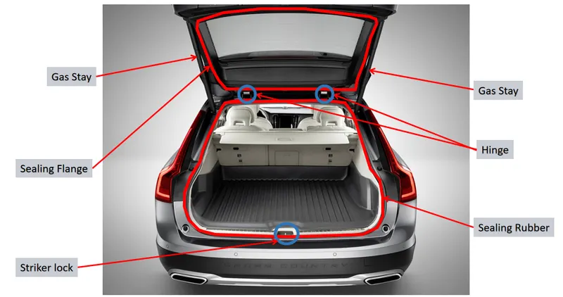
- Top Mounted Door
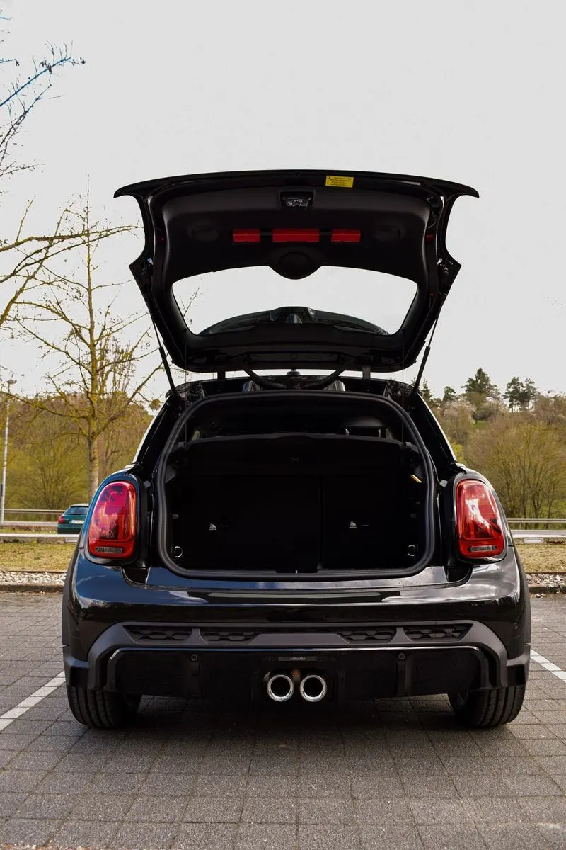
- Side-mounted Door

- Bottom Door
Procedure
Outer Upper Panel Creation:
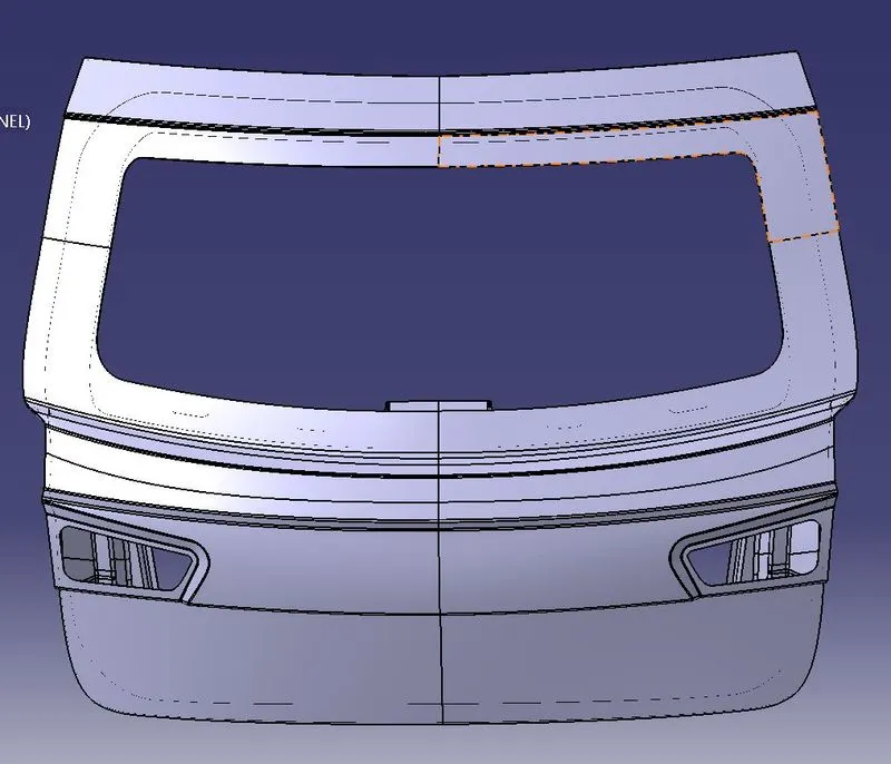
Initially, we will be creating the Outer Upper Panel by first importing the styling surface in CATIA VS.
Since the styling surface is having some issues, we need to fix this by creating a new surface in place of the irregular surface.
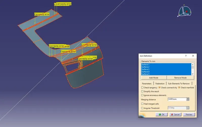
Note: As per the industry standards this operation is not recommended to be done by the Design Engineer. There will be a separate team whole will be working on the styling surface.
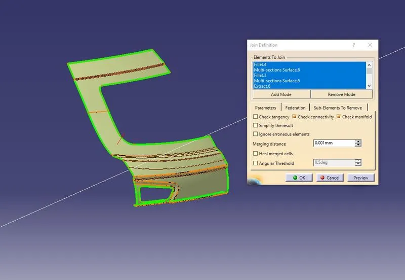
The surfaces can be created with the help of Multi-section, Extrapolate, Bi-Tangent Fillet & Spline and then the necessary fillets are provided to the sharp edges.
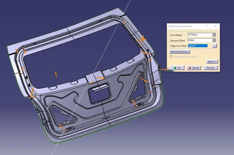
Once all the fillets are done make sure to check if the outer panel is offsetting/thickening to the required limit.
If the outer panel is not thickening due to sharp edges then we need to provide a bigger fillet value to avoid the sharp edges.
A tooling axis is also created in a direction through which most of the surfaces of the Back Door Panel are clearing the draft direction. This is done to make sure the part is manufacturable & clear the draft analysis.
Inner Panel Creation:
First, offset the outer panels to 1.7mm downwards (Outer Panel Thickness=0.75mm downwards & Inner Panel Thickness=0.75mm upwards, and a clearance of 0.2mm is maintained).
Note: This offset surface of 1.7mm will be the top surface of the inner panel.
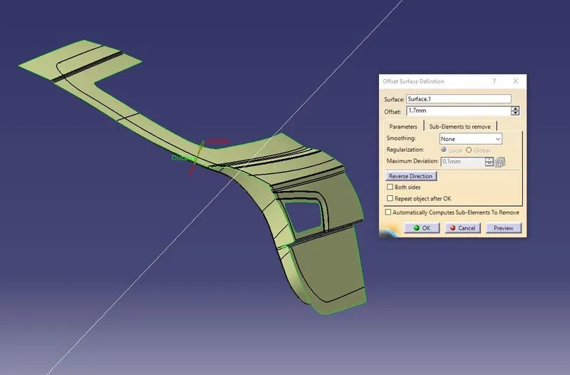
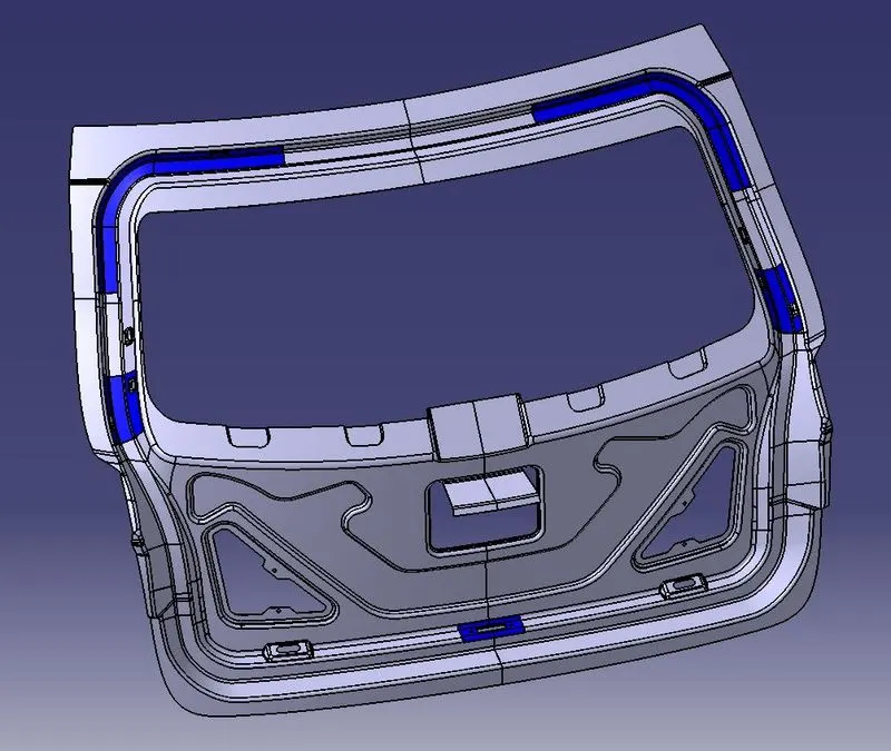
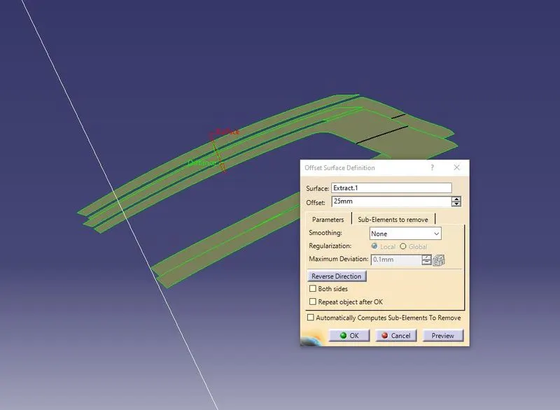
Now offset the outer upper panel to 25mm downwards and use the parallel curve option to cut the elements (to create a Sealing Flange) as shown in the below figure.
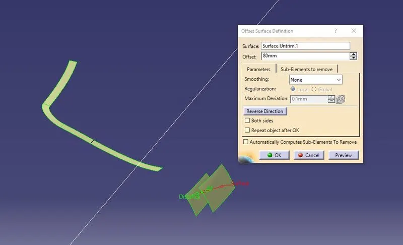
Offset the Outer Lower Panel to 80 mm downwards and use the same operations as above to create the remaining Sealing Flange.
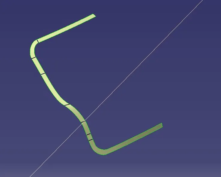
Join the Sealing Flanges by creating a surface between them using Spline & Multi-Section Surface.
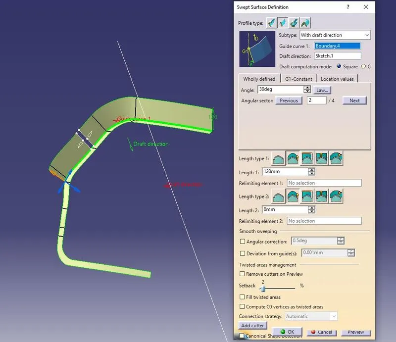
Using the Sweep option, create a surface with an angle of 25 degrees with the tooling axis.
Using the offset surface of 1.7mm, trim this sweep surface.
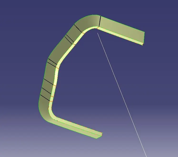
Now to create the windshield area of the inner panel, extract the surfaces nearer to that area from the 1.7mm offset surface. Sweep the sealant flange inner edges with an angle of 25 degrees inside and trim it with windshield extract.
join all the Surfaces using Tri-Tangent Fillet.
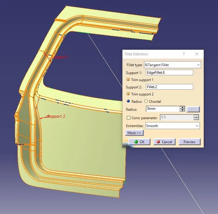
Similarly, create the lower side surface using the spline & multisection option and join them.
Creating surface for applying mastic:
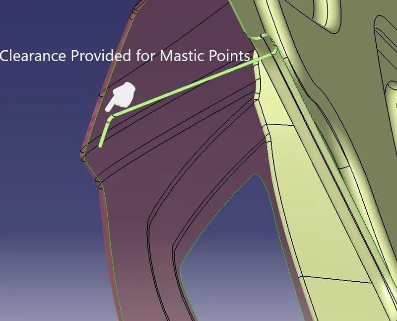
To apply the mastic, we need a surface which is having a 5mm clearance with the outer panel.
A cutout of rectangular shape is provided below the windshield area and using its edge a surface is created perpendicular to its base surface.
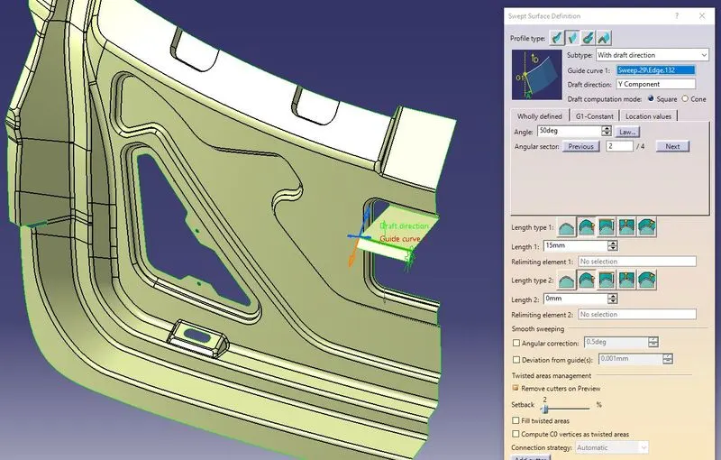
Now to create a surface for applying mastic first, offset the outer panel surface to 5mm.
Trim the outer panel with the sweep surface and remove the excess portion of the mastic surface by using the split option.
Emboss Creation
To reduce the impact of an accident on the Back Door Panel, Embossments are created below the windshield area.
Create a sketch for embossments in such a way that the forces acting during an impact results in lesser damage to the occupants & as well as to the vehicle.
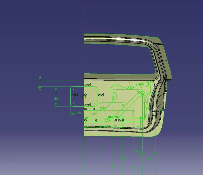
Project this sketch on the surface and split the surface using it.
Sweep the edges inside and using its base surface, trim these sweep surfaces to form the embossments.
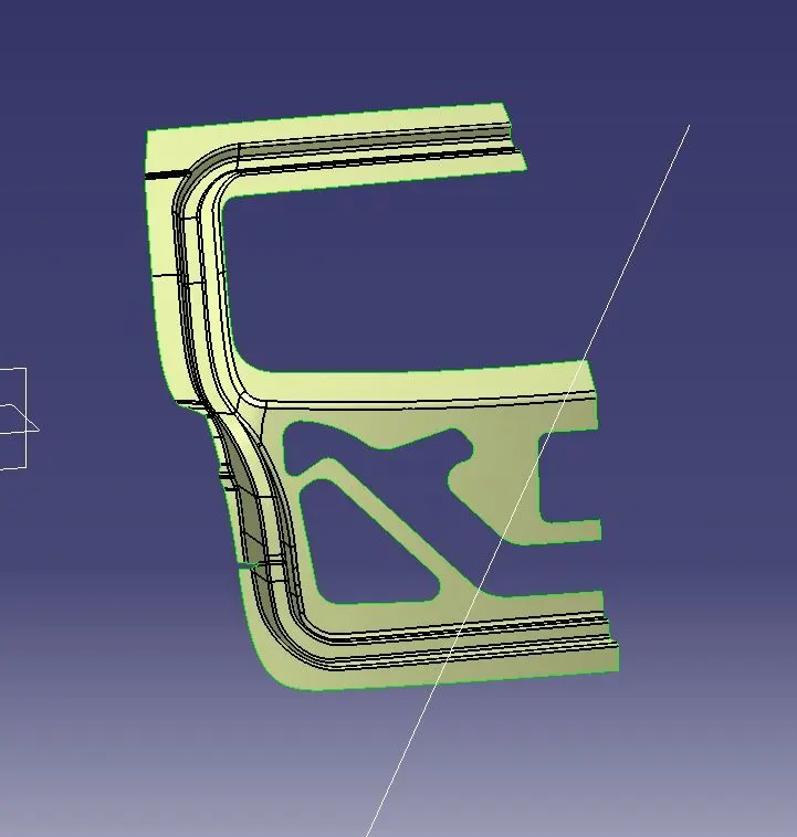
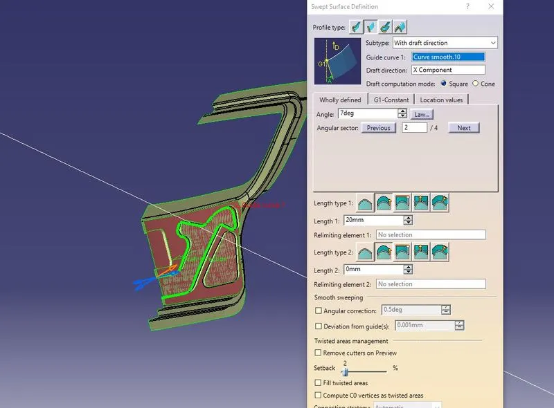
Follow the same procedure for the embossments at the windshield area as well.
Gas Stay Embossment: Gas Stay Embossment is created at the sides of the inner panel by following the same procedures as mentioned in the case of hinge embossments.
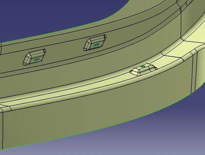
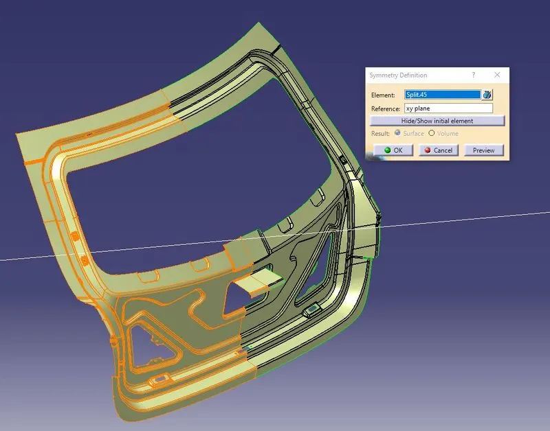
Now after working on all the required features do a Symmetry of the Inner Panel using the midplane as the reference
Latch & Stricker:
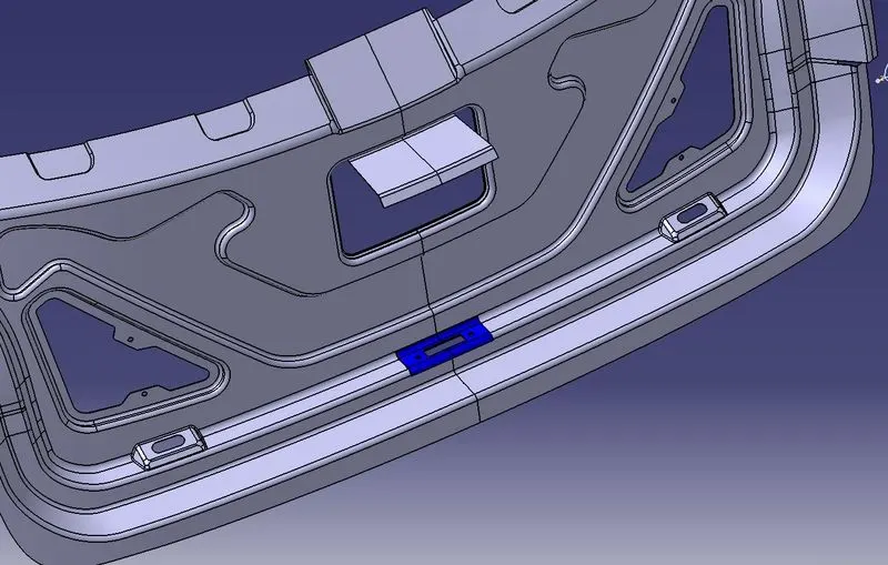
To make the Latch Embose we need to take a midpoint of the hinge axis and make a Circle around it.
Now, Where the latch is Going to be fixed make a line perpendicular to it and make that line tangent to the circle drawn before
Then make the required Slots and reinforcements for the latch.
Reinforcements:
To create the reinforcements, select the surfaces with the nearby areas and extract them. Cut the excess portion by first creating a line on the surface and then splitting the surface using it.
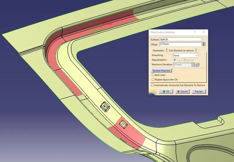
Offset the surface to 0.75mm.
Reinforcements for all the parts are created by following similar operations as mentioned above.
Hemming Creation
Now to create the Hemming portion for the upper panel, offset the outer upper panel to 2.65mm downwards (considering the thickness of both outer & inner panels as 0.75mm and providing a clearance of 0.2mm).
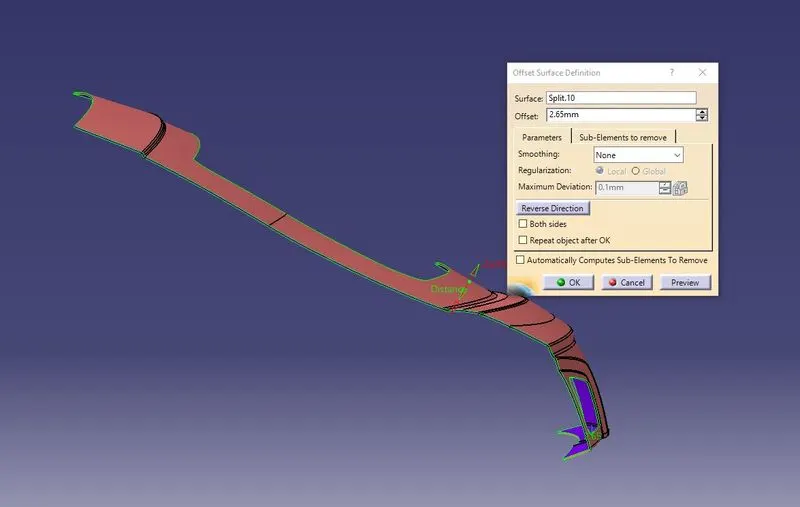
Offset the outer edges of the offset surface to 8 mm using the parallel curve option.
Split the offset surface with the offset curve & make sure to check whether this surface is thickening or not. This is done to make sure the surfaces won't create any problems while thickening at the end.
Now make a sweep by extracting the Boundary as Guide Curve & Reference Surface as the outer panel at an angle 90deg with a length of 3mm
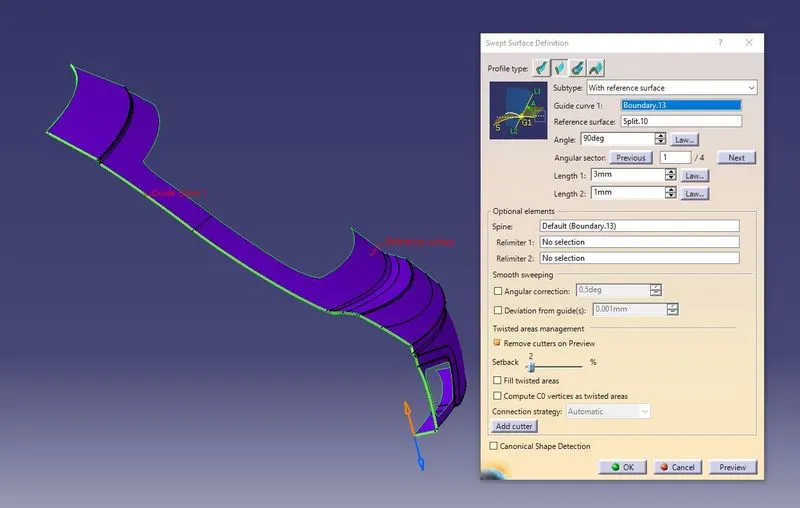
As there will be some angular discontinuities in the sweep we need to rework and make it into a tangential surface then only we can get the hemming of the Outer panel
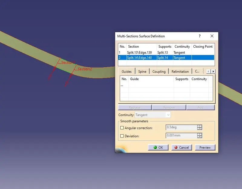
So, where and all the surface is not good we need to Split that part and do a patchwork with the multisection surface as shown in below fig
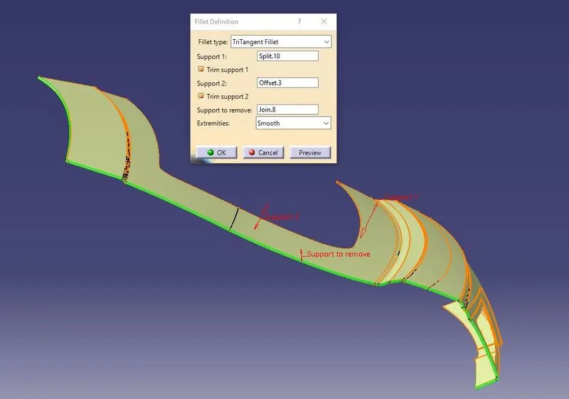
Give a Tri-Tangent filet by selecting these 3 surfaces. (Outer panel, Sweep, Outerpanel Offset)
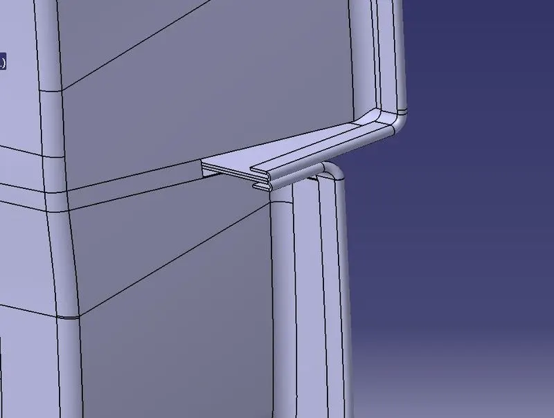
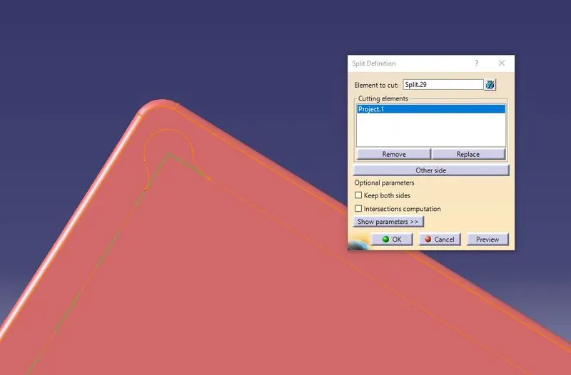
Near the corner, we will be providing relief. This will be done with the help of a parallel curve/Sketch, spline & split options. Using the relief curve and split the surface to form a relief at the corner.
Generating Solid :