Week 11 - Final project
OBJECTIVE
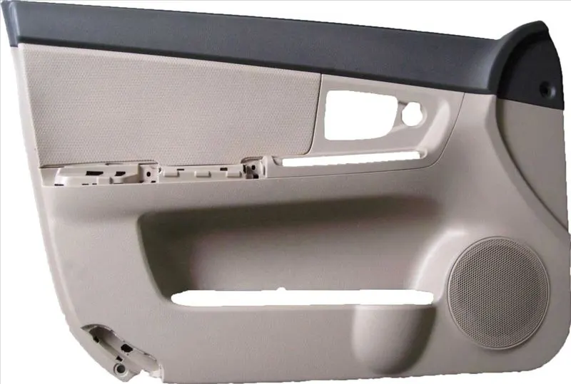
The objective of this project is to create/design a CAD model of a Side Door Trim component from the given Class-A surface using CATIA.
INTRODUCTION
Importance of plastics in the automotive industry
Plastics play an important role in the automotive industry as the market in recent times demands lightweight, affordable, fuel-efficient, safe, comfortable, and high material performance automobiles. Plastics have been used in cars since the early 1950s, but it’s the latest innovations that are changing the industry for the better. Engineered polymers and plastics are continuing to replace aluminum and other metals in automobiles, with the average car interior now being made up of over 50% plastics. Over 1,000 different car parts are now made of plastics, and these plastics can be moulded together to replace the need for multiple parts, keeping manufacturing efficient and weight down.
Plastics also weigh significantly lower than their other counterpart materials(like sheet metal) with a weight reduction of up to 50% which can improve fuel efficiency by 25-30%. The plastic used in cars means that for every kilo lost, your car will emit 20 kilos less carbon dioxide over its operating life which contributes to a greener environment. Plastics also offer lightweight solutions which fulfill essential safety requirements. So it can be said that the plastic industry, in a way has revolutionized the automotive industry(and this is not just about cars).
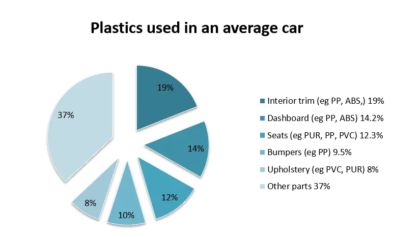
One more reason for using plastics is manufacturability. It has low manufacturing costs along with easy manufacturability. Single mould components have allowed car manufacturers to decrease assembly time as well as to introduce design innovations at a decreased cost. The fact that plastic can be moulded more easily, allowing components to be tailored for more comfortable human-ergonomic features. It also allows for more streamlined and aerodynamic shapes to be made. As less material can be used compared to if steel was used for components, plastics ensure a longer and more reliable vehicle lifetime.
Now that we understood the importance of plastics in cars, we'll take a look at the major types of plastics used in a car.
- Polypropylene
- Polycarbonate
- Acrylonitrile Butadiene Styrene
Design Plan
- Class A surface extraction.
- Separate and sort the single Class A surface into respective components using Geometrical sets.
- Necessary Main/Side Tooling axis creation.
- Draft Analysis on Class A surface component-wise.
- Class B surface obtained after offset and extrapolation in the appropriate direction.
- Class C surface created using Tooling axis as reference draft direction.
- Class A, B, and C are trimmed together to form the finished surface of different components.
- A closed surface is converted into a solid followed by a draft analysis of the solid component.
- The various attachment features were created on the Class B surface while following the design guidelines.
Class A
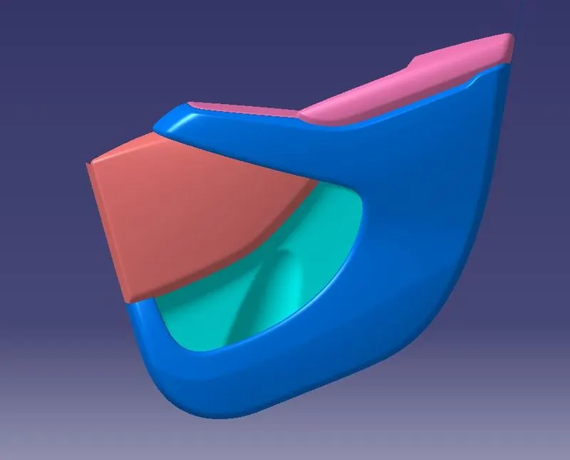
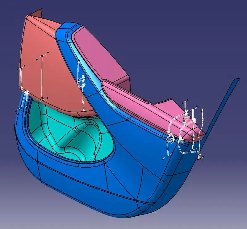
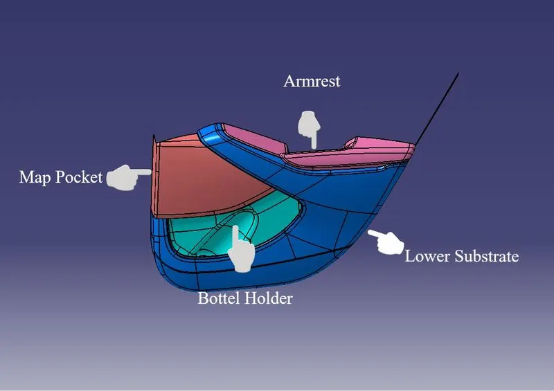
In Automotive Industry There Will Be a Dedicated Team Who Will Perform The Aesthetic Designing Of Various Components Including The Whole Vehicle. They Will Create Various Concept Sketches After Ideation. After That, They Will also create a Class A Surface Of The Product. This Class A Surface Is Then Passed OverTo The NPD CAD Team. They Will Initially Inspect The Class A Surface In Order To Check If The Design Is Manufacturable Or If It Is Following The Engineering Principles. If There Are Any Issues About The Design, They Will Contact The Product Design Team And Will Ask To Modify The Class A Surface In Order To Solve The Problem. Here I Received The Class A Surface and Master Section As Shown Below.
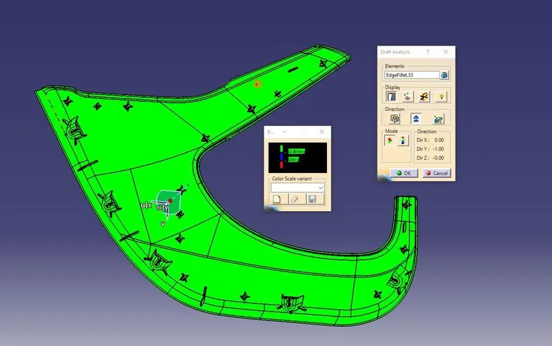
Initially, we need to check the Draft Analysis of every part given to us, to Check the Draft Analysis we need to create a Tooling Axis for every part.
Tooling Axis
The Tooling Direction is the direction that the mold pulls apart. The mold is built into two separate pieces. You have a Cavity side and you have the Core side. The Core pulls apart from the Cavity and that's the Dyeline or the Tooling Direction.
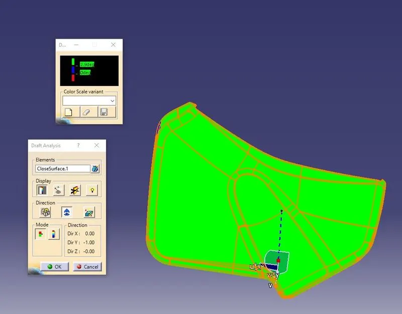
We've provided a minimum draft angle value of 3 degrees which should be cleared by class A in every direction and the green color indicates that the angle is above 3 degrees in all directions.
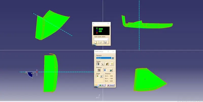
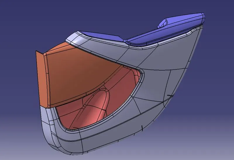
For surfaces that don't clear with a single tooling axis, we have introduced a secondary side tooling axis/Lifter axis with which we clear the issue.
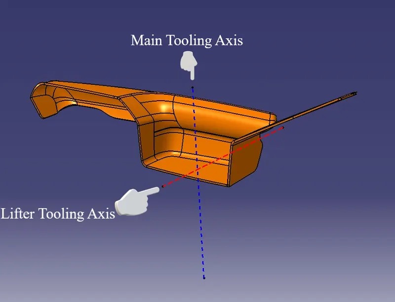
The Red-colored axis clears for that specific region and this region, instead of moving in the main tooling direction, is taken out with a lifter in the secondary axis direction.
Parting Line: A parting line is a borderline in which draft angles change direction. That means, it is the dividing line that splits the core and cavity halves of a moulded part. It is sometimes a starting point for the mould parting surface.
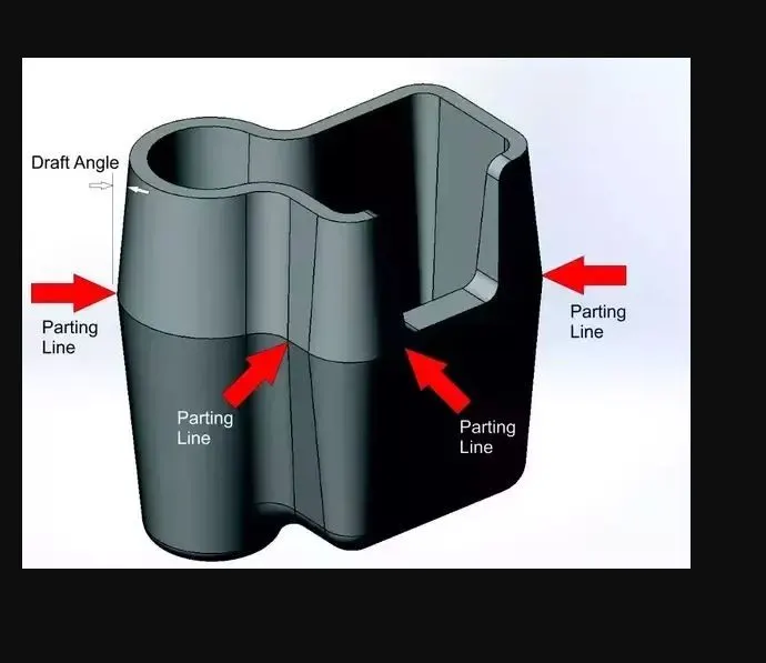
Parting Surface: Parting Surface is the point of a plane where the cavity meets the core in a larger area with zero tolerance gap and prevents the leakage of the molten metal out from the mould.
Class B Creation
Next, we proceed to Class B surface creation. Class B refers to the non-aesthetic surface that is not visible to the naked eye when looked upon from outside but rather connected to the other parts of a car using attachment features that lie on this surface.
For obtaining a class B surface, we simply offset the class A surface by the required distance(thickness of the component) in the correct direction.
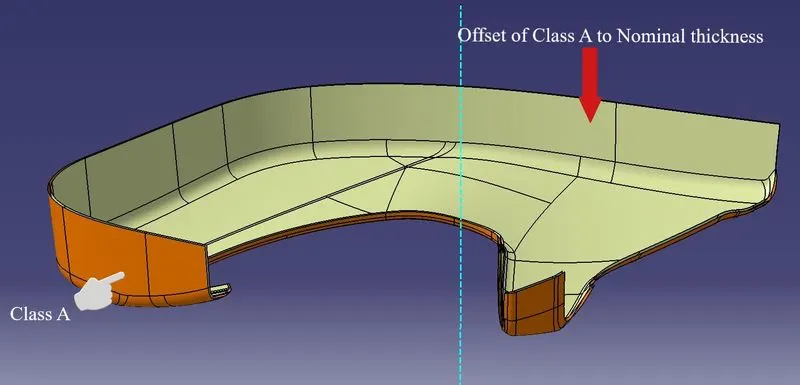
Class C Creation
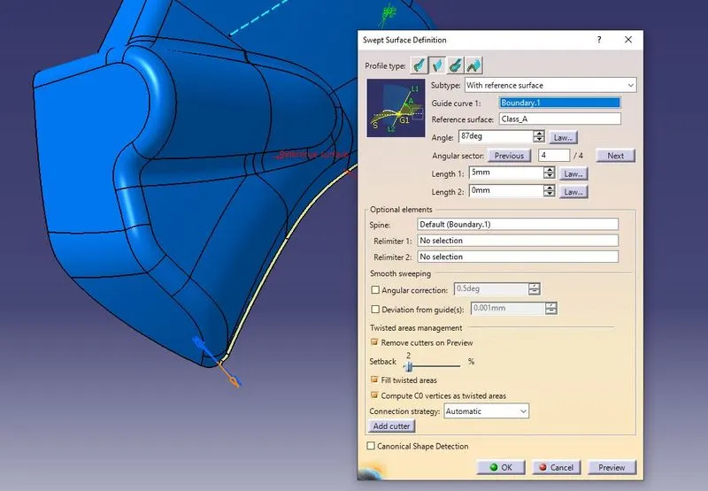
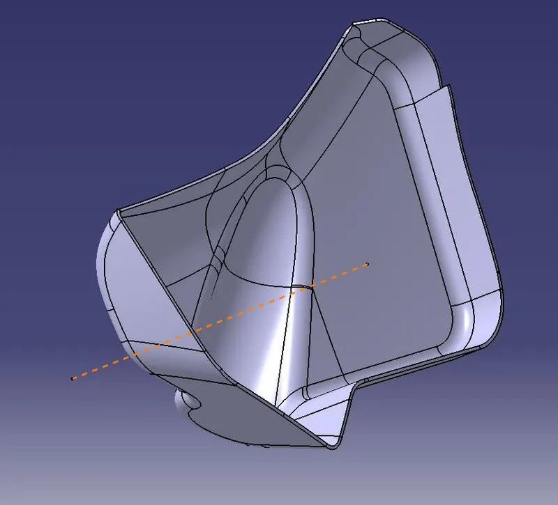
After this, we create a class C surface that forms the thickness/cross-section of the solid part. For class C surface, we use a combination of commands such as sweep, multisection surface, extract and extrapolate to obtain the surface and then join them together to form a full surface.
By Using the Sweep with reference to the Surface at an angle of 87deg we get the C surface from thereafter creating the sweeps around the bottle holder trim the unwanted surfaces & add the created c surface to Class A.
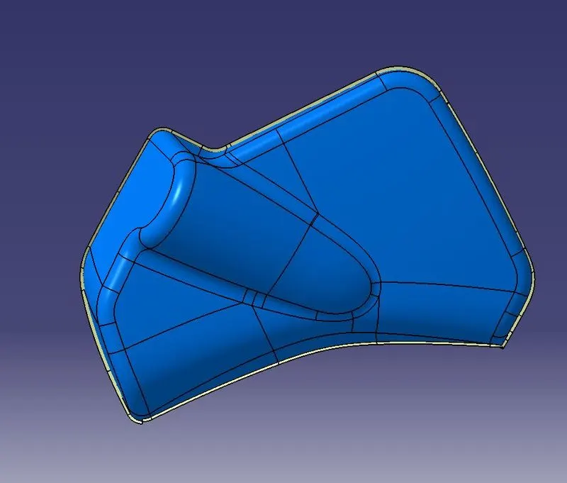
We need to check for the Draft analysis of the Class C surface also with a 3 deg angle
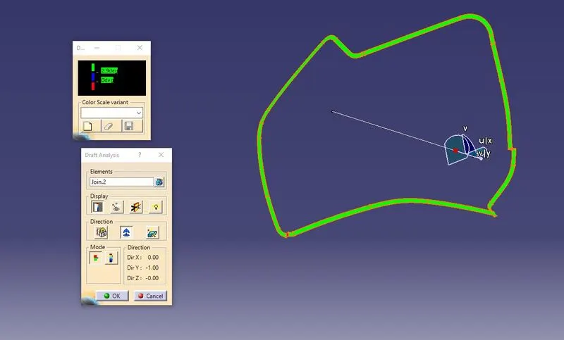
Then after we need to join all the A, B & C surfaces using the Join command which will give us a Closed Solid Body. Now we need to Check the Draft analysis of the Final Solid part to move further.
 /
/
CLOSED BODY DRAFT ANALYSIS
All the 3 class surfaces must pass in this analysis.
Insert > Analysis > Feature Draft Analysis
Note: Ensure you have the Material view mode ON.
- Define the Draft direction using the "Compass" option.
- Drag the Axis system representation close to the model and align it along the tooling axis.
- "Lock" the Draft direction.
- Set the Colour scale
- Place the Analysis Tool (Arrow Icon) anywhere on the model and review the colors on the feature.
- If any feature (especially C surface) is showing Blue/Red then choose the same option again (It will switch to Analysis under Running point) and place it on the respective feature to review the deviation of the sweep angle from the Tooling Axis.
| Colour | Description | Value |
| Green | Core Side | Above 3° |
| Blue | --- | 0° |
| Red | Cavity Side | Below 0° |
In this manner, we create the solids for all the components in our model.
B Side Features/Attachment Features
Attachment features on the plastics have many uses like improved strength of the component, attach one component with another, locate a component for mold to move it(to pour the molten plastic), arrest motion of one component concerning another, and attaching the finished plastic to the metal BiW(Body In White).
The first set of features that we are going to create are heat stakes and Locator(4-way and 2-way locators).
Heat stakes or the process of heat staking also known as thermoplastic staking is the process of joining two dissimilar materials together. In heat staking, we use local heating and cooling to raise the temperature of plastic components and allow plastic reforming to be carried out. This reforming process attaches one plastic component with another as the plastic cools and solidifies.
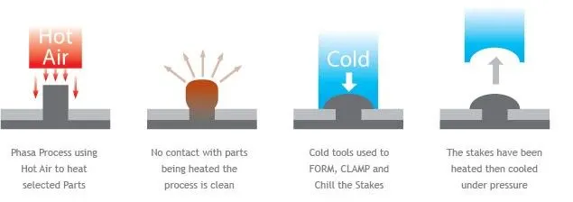
ADVANTAGES:
- Simplification of machinery
- Reduced cost of machinery
- Multiple fastening points
- Allows higher density of welds compared to hot air cold form or ultrasonic welding
Ribs
Ribs are a feature in plastic injection moulded parts. They are thin extensions that run perpendicular to a wall or plane. They are commonly used to provide additional support and strength to a part.
GUIDELINES FOR RIB DESIGN TO SUPPORT HEAT STAKES
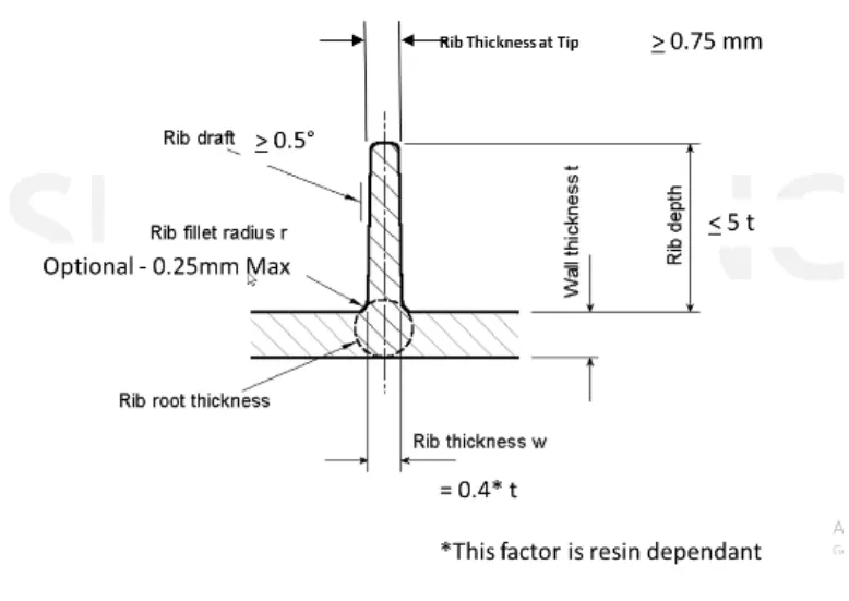
| Draft |
|
| Thickness |
|
| Fillet |
|
| Height |
|
| Base Rib Root Dia |
|
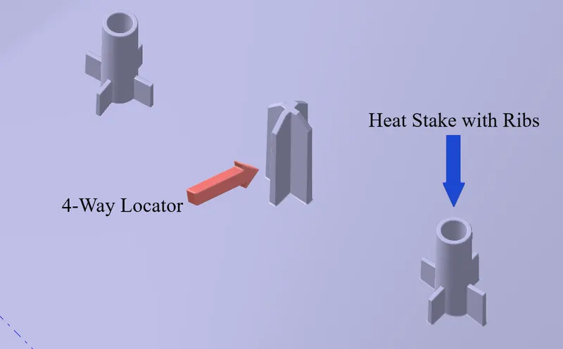
Locators
- Locator is another attachment feature that is vital to any component obtained through the molding process as it acts as a guide for the mold to move into position and there is no mismatch between the two(top and bottom) half of the mold. There are two classifications of locators, 2-way and 4-way. A simple method to remember the difference between them is to consider the 3 axes of translational motion, and the 6 corresponding directions or Degrees of Freedom.A 2-way locator restricts motion along 1 axis (or 2 degrees of Freedom), like a round pin in a slot. Likewise, a 4-way locator restricts 4 degrees of freedom along 2 axes. A round locating pin located concentrically in a hole is a common application of a 4-way locator and helps to further secure the piece. To sufficiently locate a part, a minimum of one of each type of locator is required to prevent excess motion of the workpiece, and more locating components may be used as needed.
Dog House
- Dog house is an engineering feature used in the plastic trim design. The primary function of a dog house is to avoid sink marks on the class A surface which may occur due to features such as a locator or rib on the backside of Class. So the best possible solution is to increase the height and decrease the cross-sectional thickness of the ‘legs’ by using a dog house. We can also use them for solving the necessity of large length features such as Heat Stakes And Locators which may require large lengths sometimes.
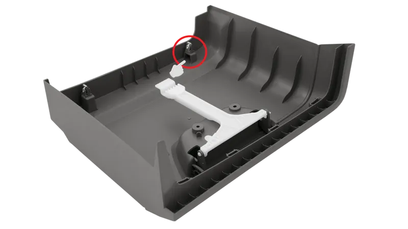
Here I used power copy to create the doghouse in the desired locations.
PowerCopy
A Power Copy is a set of features (geometric elements, formulas, constraints, and so forth) that are grouped to be used in a different context, and presenting the ability to be completely redefined when pasted.
- From the Start>Knowledgeware menu, access the Product Knowledge Template workbench.
- Click the Create a PowerCopy icon. The Power Copy Definition dialog box is displayed.
- Select the elements making up the Power Copy from the specification tree. For the purposes of our scenario, select the following items:
-
The Parameters
-
The Relations
-
Line.1 (under Geometrical set)
-
The Geometry
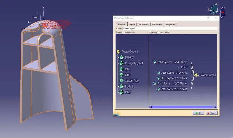
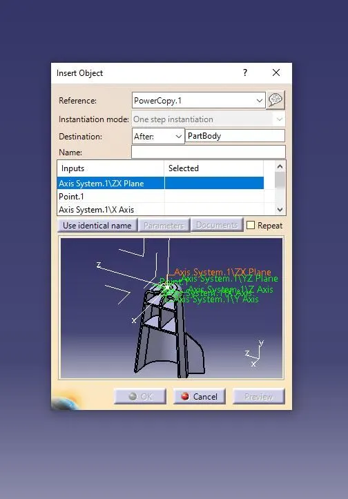
Now, when we give ok the doghouse will come and sit in the position according to the inputs.
-
As Dog house is having some extra Strengthening Features like inner ribs, We use lifters to clear them while manufacturing so that a Side Core axis is provided for it to clear the internal draft
Dog House Lifter Axis Draft Analysis
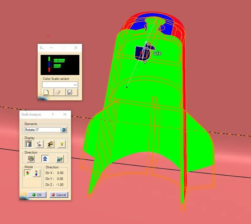
Now, in order to attach/position one component with respect to another using heat stakes/locators, we create flanges on the necessary surfaces.
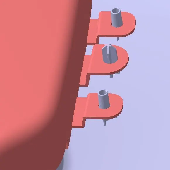
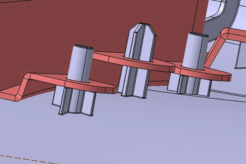
The image shown above gives an example of how flanges look in our model. I also create holes on the flange for the heat stake and locator to pass through.
I also provide a draft for heat stakes and locator in the direction of the tooling axis of the component upon which it is attached(Lower substrate in this case).
For the next feature, I consider the retainer clip for the doghouse. doghouse has basically a provision for our retainer clip to be mounted and the purpose of having a retainer clip between the trim component and the BIW sheet metal is explained below.
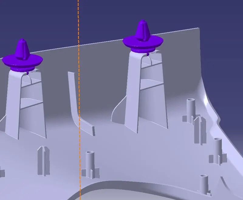
The retainer prevents door trim from being ejected in the event of a side impact and can be disassembled for servicing. Apart from these purposes, it also allows vertical and lateral gap compensation. Once in place, the clip becomes invisible, delivering added value in terms of design and aesthetics.
RETAINER CLIP
It is a feature that facilitates:
- Locating and Arresting components of an Assembly.
- Providing Alignment in Mating Parts.
- Acting as a stopper or guide for various mechanisms
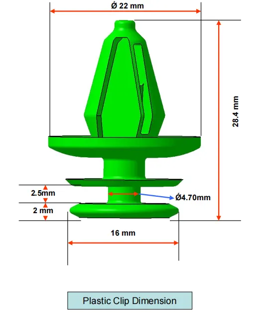
DESIGN GUIDELINES FOR RETAINER CLIP
Hereby the entire designing of the door trim with its attachment features is done by Following the DFM & DFA principles
Design for Manufacturing (DFM) is a design method to reduce the complexity of manufacturing operations and the overall cost of production including the cost of raw materials. Design for Assembly (DFA) is a design method to facilitate or reduce the assembly operations of parts or components of a product.
Examples
- 95% of the flanges designed here come with in the die. only 5% flanges are designed according to the lifter/Slider arm manufacturing Process which in turn reduces the manufacturing cost and at the same time reduces the complexity of more no. of lifters.
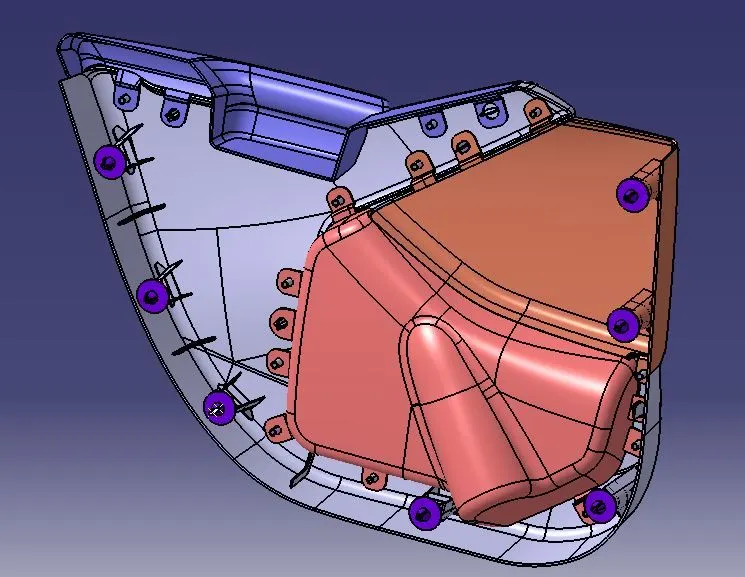
- All heat stakes are designed according to the ease of access for the heat staking Machine by considering all the other parts assembling environment.
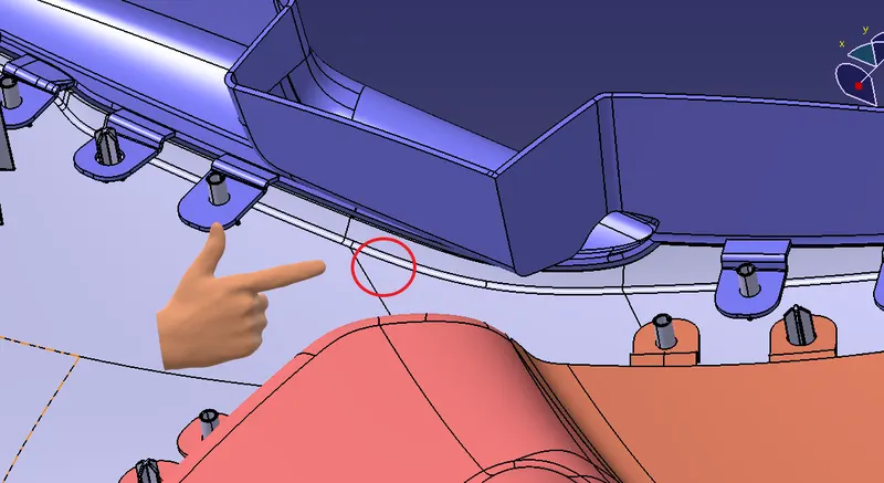
Here in the above fig, we ignored a heat stake in the pointed area because the armrest obstructs the area while assembly and makes it a blind spot where we can't able to access the heat staking machine.
Design for Assembly (DFA)
DFA involves design for a product's ease of assembly. It is concerned with reducing the product assembly cost and minimizing the number of assembly operations
- Minimize part count.
- Build fasteners into the part design.
- Pay attention to symmetry.
- Make it impossible to install parts incorrectly.
- Optimize your tolerances.
- Design using COTS parts.
- Use the same tools across assemblies.
- Discover the surefire way to ensure your parts meet DFA guidelines.
Conclusion: Hereby we Developed the entire Door Trim Panel by considering all the Injection moulding Rules and limitations and followed the DFM & DFA for the Ease of Manufacturability.