Week 8 - Challenge 3 - Switch Bezel Design
Aim: To design the new component as per the requirement by Considering the given CLASS A as a reference.
Procedure:
- Initially, we need to perform the draft analysis for class A, because we are considering it as the parent to create the new component.
- To do the draft analysis we need a tooling axis. So for creating the tooling axis we need to project the intersecting 3d element of class A on both XZ & YZ planes
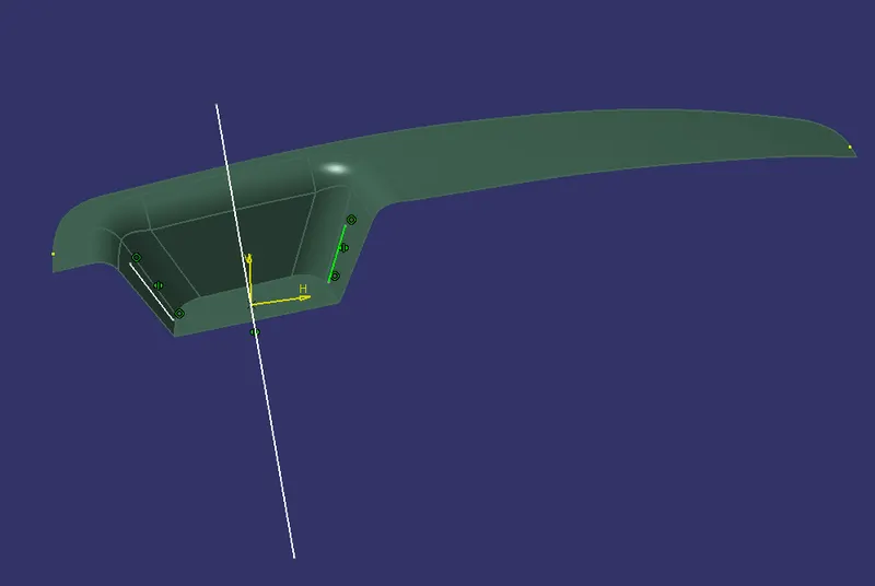
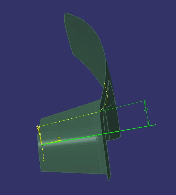
Fig1: Bisecting line created in XZ plane Fig2: Bisecting line created in YZ plane
- Create a bisecting line in both planes by sketching two lines on the edges of the intersections.
- Now create another bisecting line by the reference of both bisecting lines which were created in XZ & YZ planes, Which is considered as the Mian tooling axis.
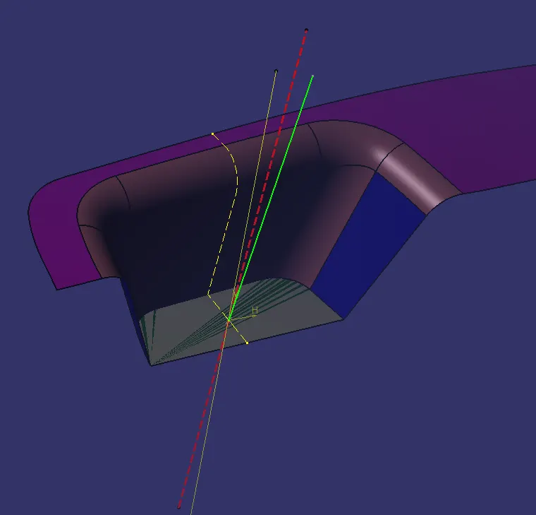
Fig 3: The Red Coloured dotted line is the Tooling Axis
- Now Perform the draft analysis for Class A
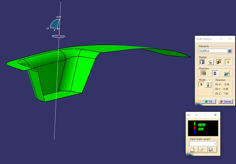
- After Solving the draft analysis for class A we should start creating the B and C Surfaces
- Now extract all the plane surfaces from class A, Untrim and Extrapolate those surfaces
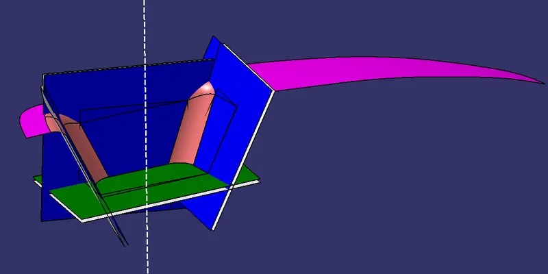
Fig 4: Extracted plane Surfaces by neglecting the filleted surfaces
- now offset those extrapolates to the required dimension and trim the extra surface edges which are not needed
-
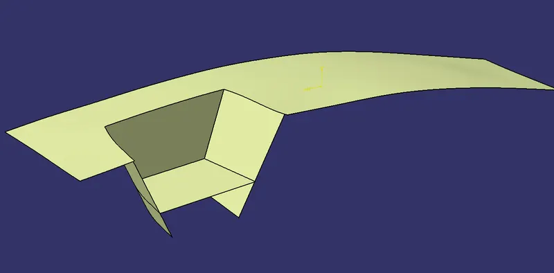
- Now give the fillets for the edges where needed and check the measurement of those fillets they should be at the same value of the offset (3mm)
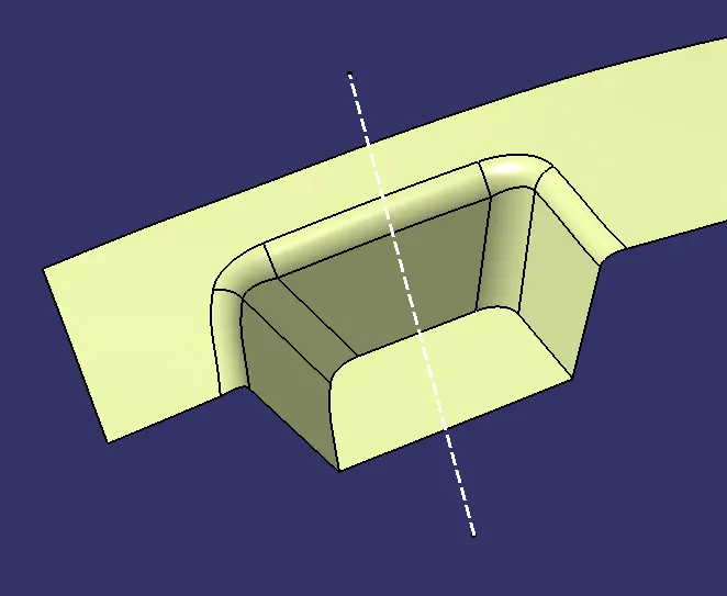
Fig 5: The Above Fig is CLASS B surface
- Now by taking the boundary of class A as reference Sweep it using the draft direction at an angle of 3deg.
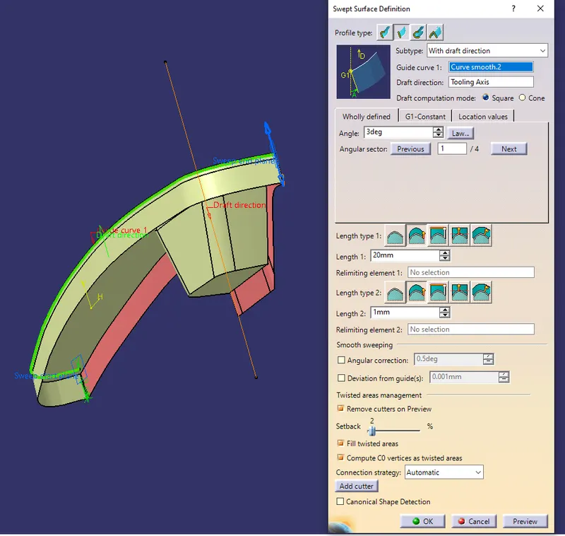
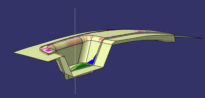
- Now do the final trims and create the CLASS C surface. Trim Class C from Class A Then we will get the final output of the new closed Surface Component.
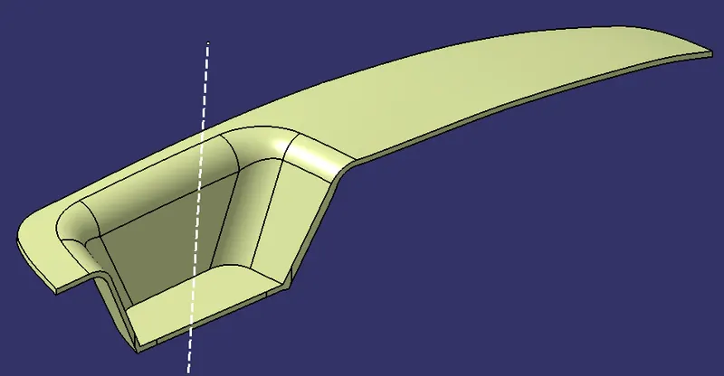
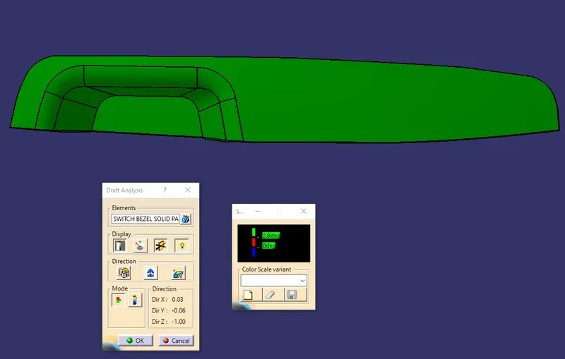
- Now Jump to Part Workbench and make this Surface component into solid by using Close surface and perform the draft analysis on it.
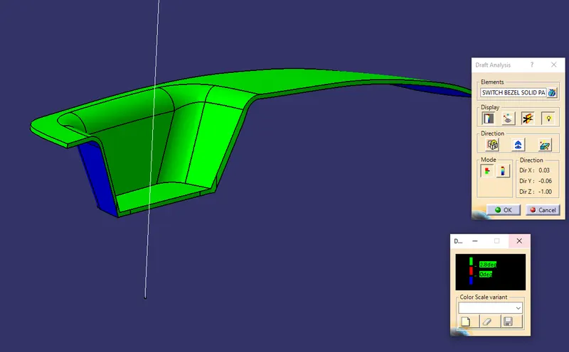
Fig 6: Draft Analysis of the solid part obtained from the closed surface
- Finally, the publications of Tooling Axis, CLASS A, B & C are to be done.
RESULT: Switch Bezel Plastic component through the given Class-A surface is obtained and the detailed Draft Analysis is also performed and solved.
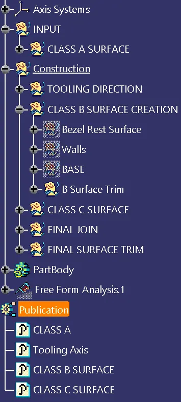
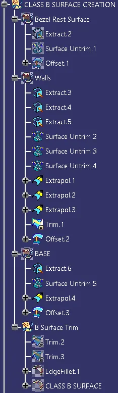
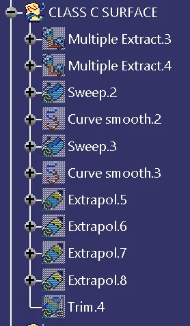
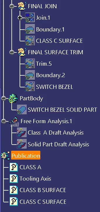
Detailed View of the Specification Tool Tree
Isometric view
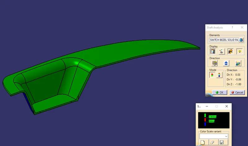
Front View
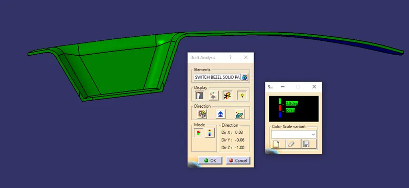
Side view
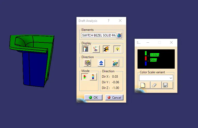
Top view