


Courses by Software
Courses by Semester
Courses by Domain
Tool-focused Courses
Machine learning
POPULAR COURSES
Success Stories

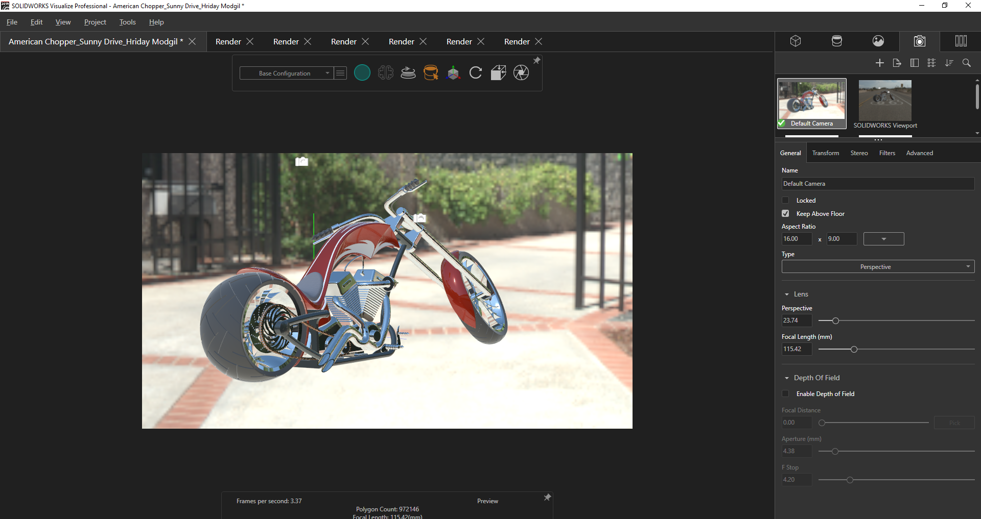
Photo Realistic Rendering
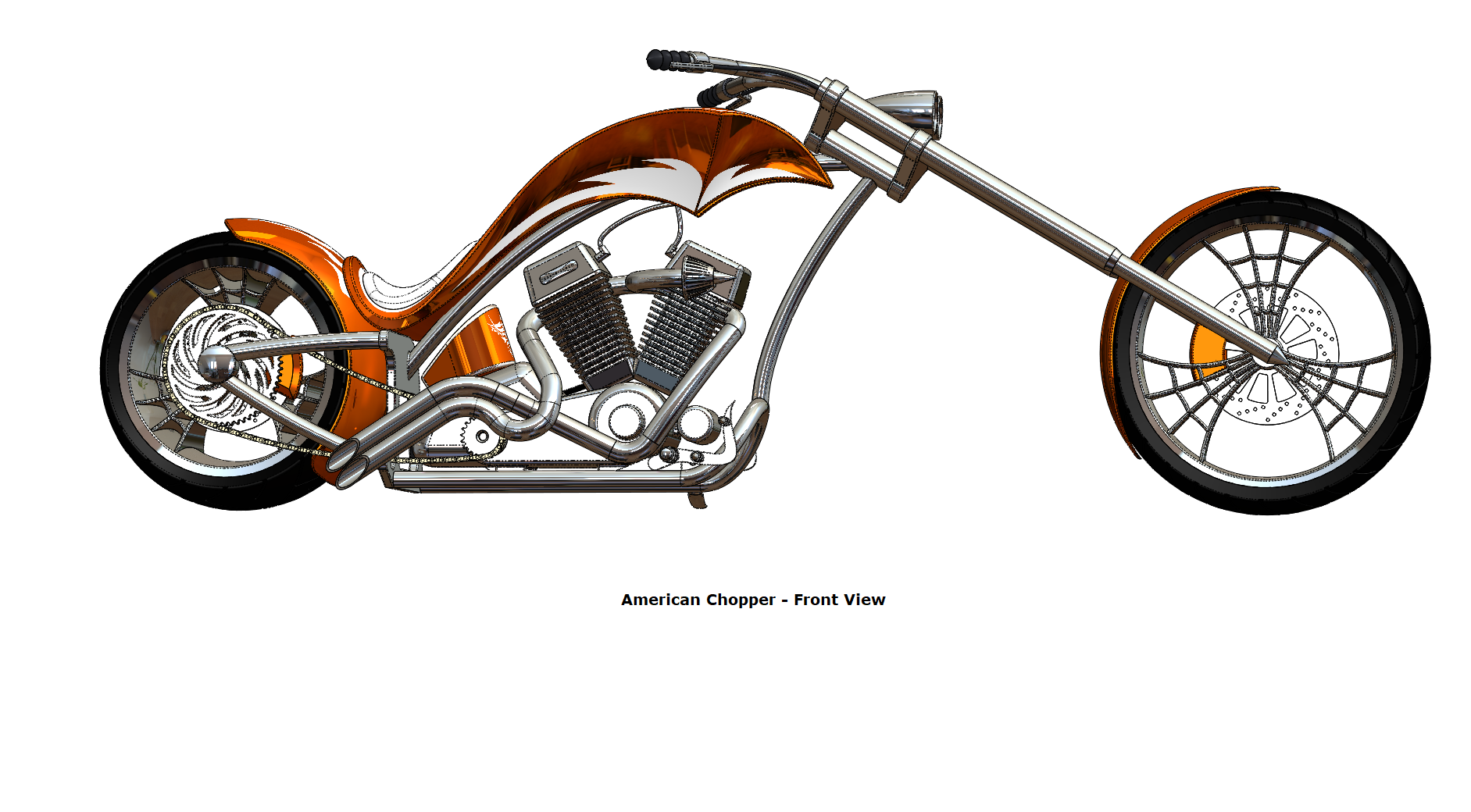
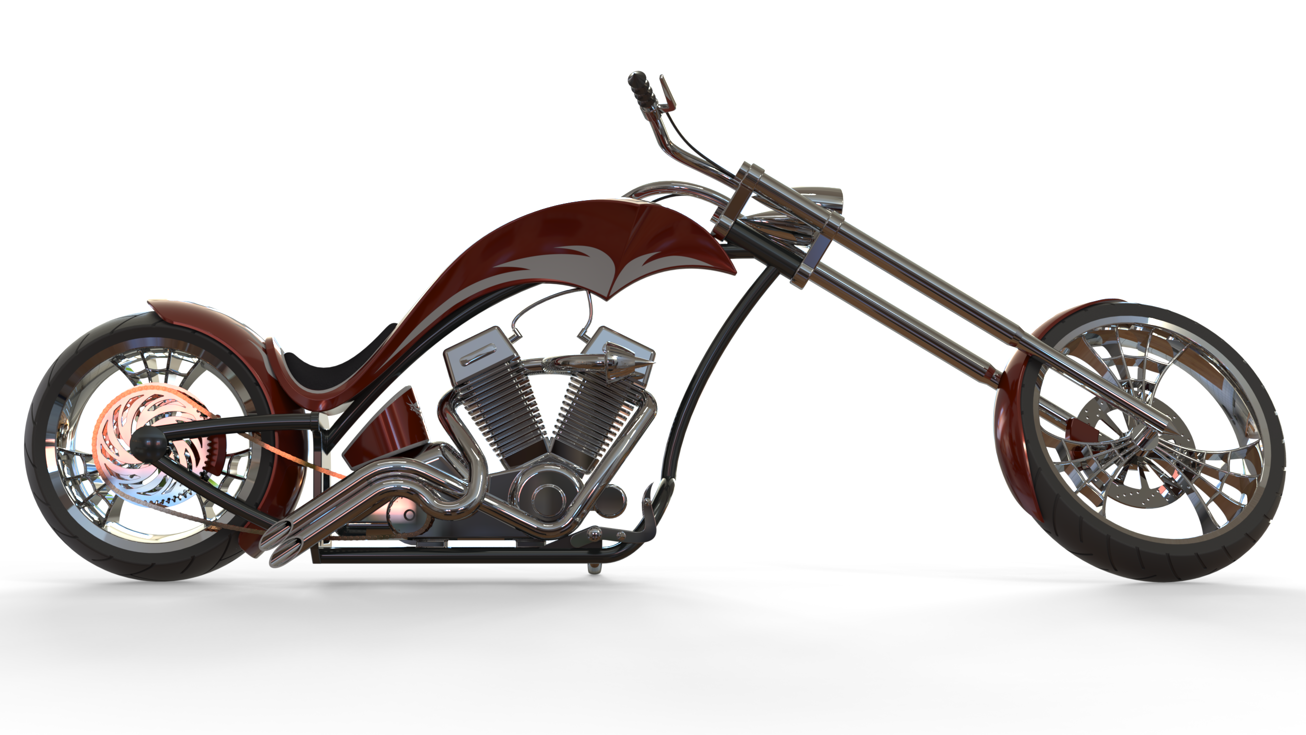
The American Chopper - Assembly & Render Objective To learn the concepts of part modelling and assembly modelling for designing The American Chopper in SolidWorks and also to learn basic concepts of photo-realistic rendering to generate a render of the designed Chopper in SolidWorks Visualize. Introduction In…
Hriday Modgil
updated on 30 Oct 2020


The American Chopper - Assembly & Render
Objective
To learn the concepts of part modelling and assembly modelling for designing The American Chopper in SolidWorks and also to learn basic concepts of photo-realistic rendering to generate a render of the designed Chopper in SolidWorks Visualize.
Introduction
In this project, we will design individual parts of the American Chopper in SolidWorks by making use of various sketch tools, solid and surface features, curves and reference geometries and later create an assembly to relate all the individual parts with each other to get a fully designed motorcycle. Each part will utilize various tools/commands used in SolidWorks to help us understand their purpose in solid modelling. We will be giving some geometric definitions to the sketches by adding some relations which will enable us to make any variations during the design process. This technique/approach that we are going to use in this project is called feature-based parametric modelling.
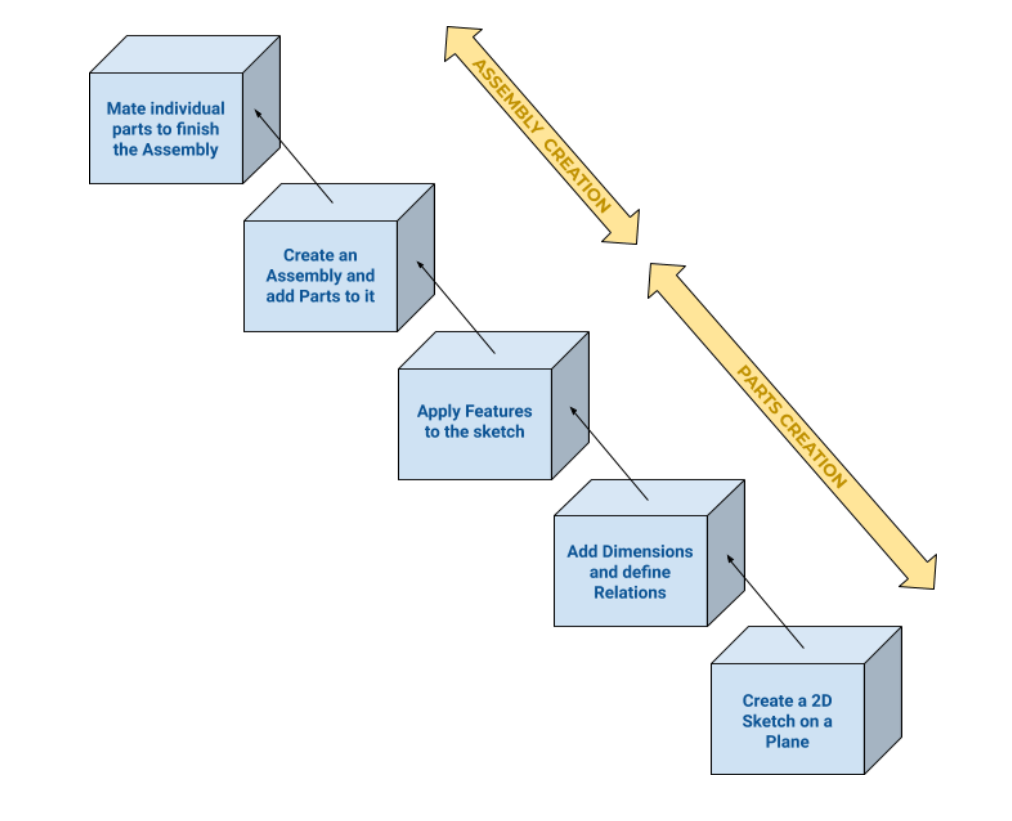
Design Approach
The Parametric feature-based Bottom-up approach has been followed in the modelling of this American Chopper. Please refer to the Flowchart below:
Description
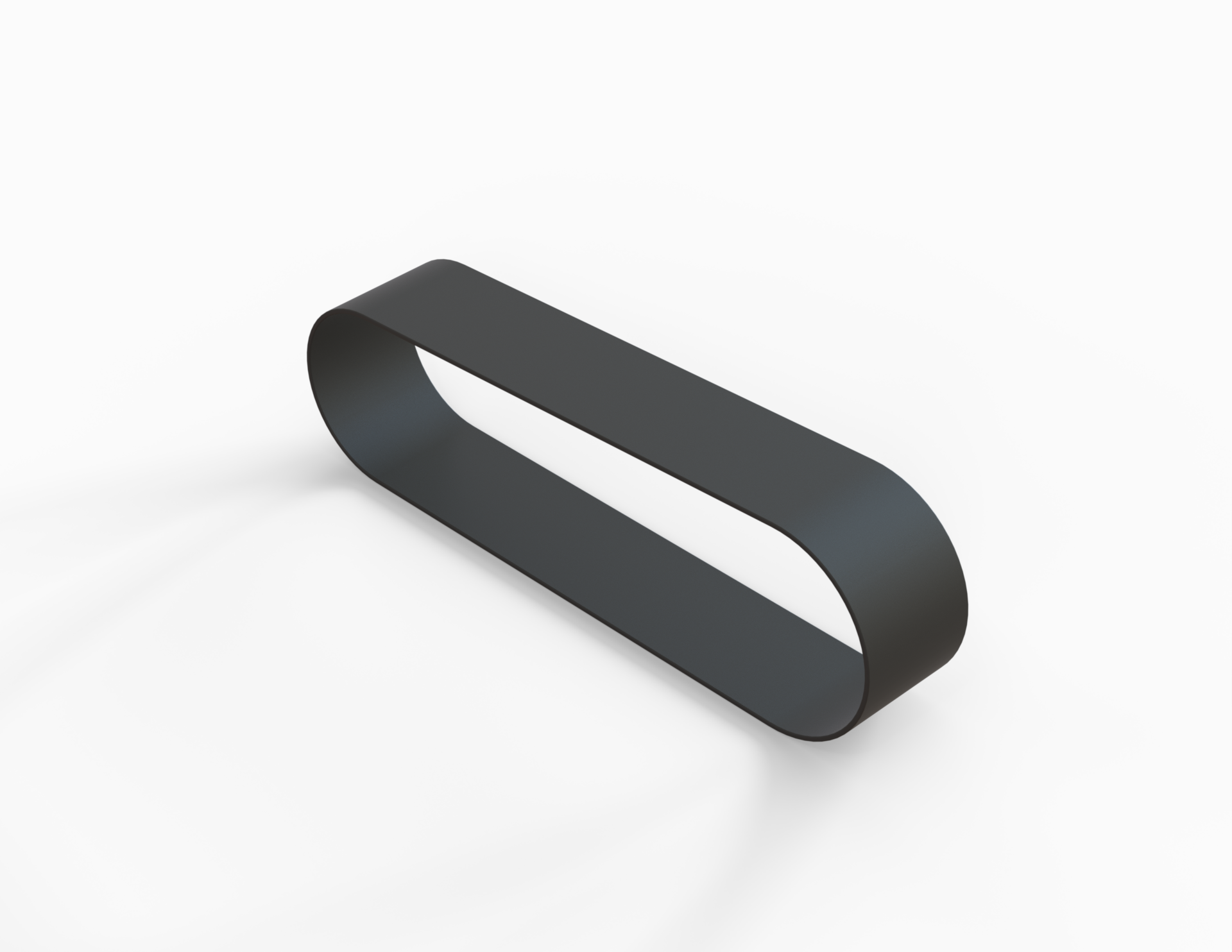
Transmission Belt
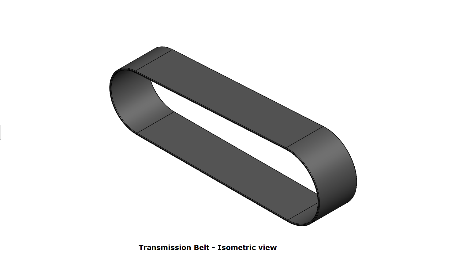
Tools/Features used:
- Extruded Boss/Base: This feature extrudes an entire sketch or its selected contours in one or both directions (upto a specified distance which can be altered by the user) to give a desired 3D part.
- Fillet: We can apply this as a sketch tool while creating our sketch or as a feature after a 2D sketch is transformed into a 3D feature. It rounds the corner of two sketch entities at their intersection point creating a tangent arc. When applied as a 3D feature (solid/surface), it creates a rounded internal or external face along one or more edges.
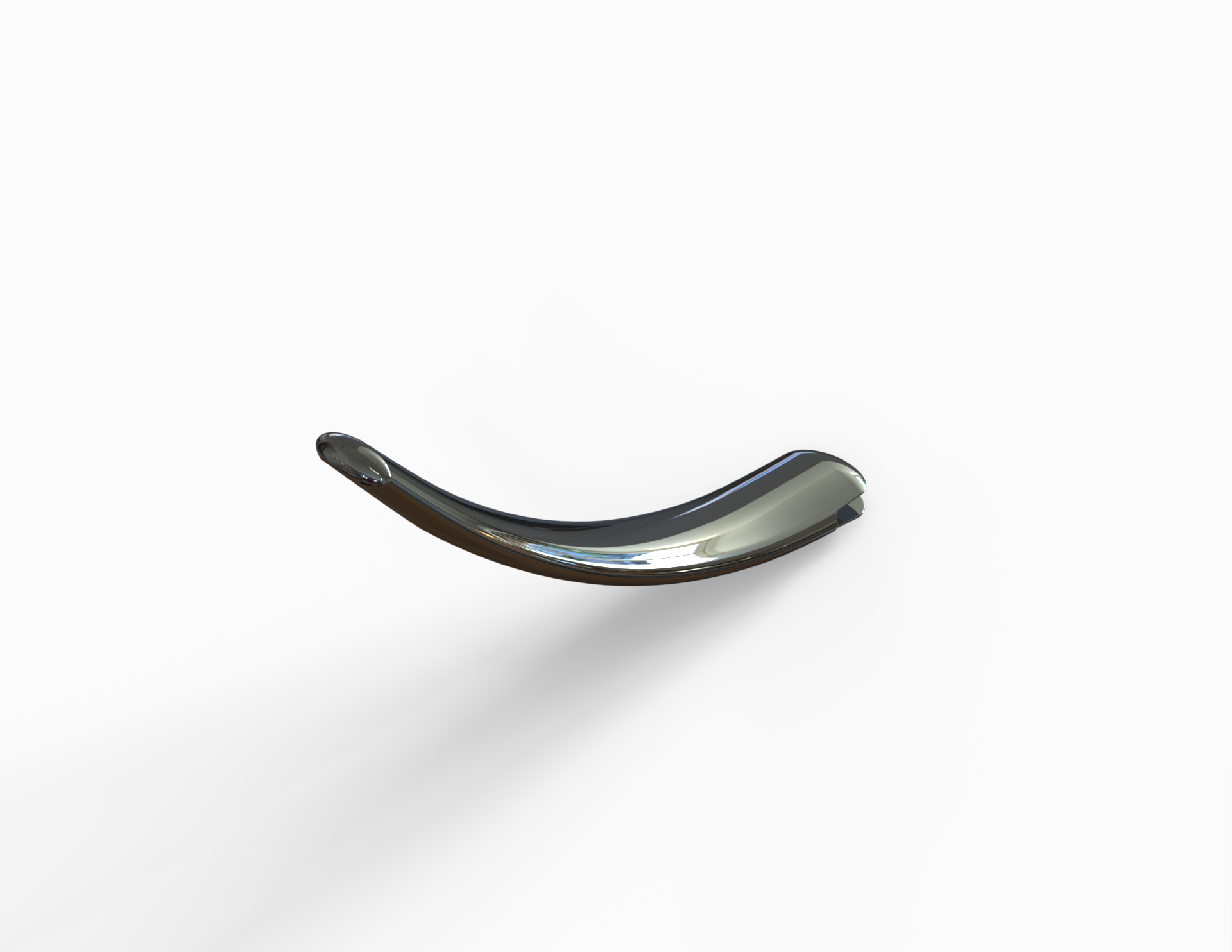
Kickstand
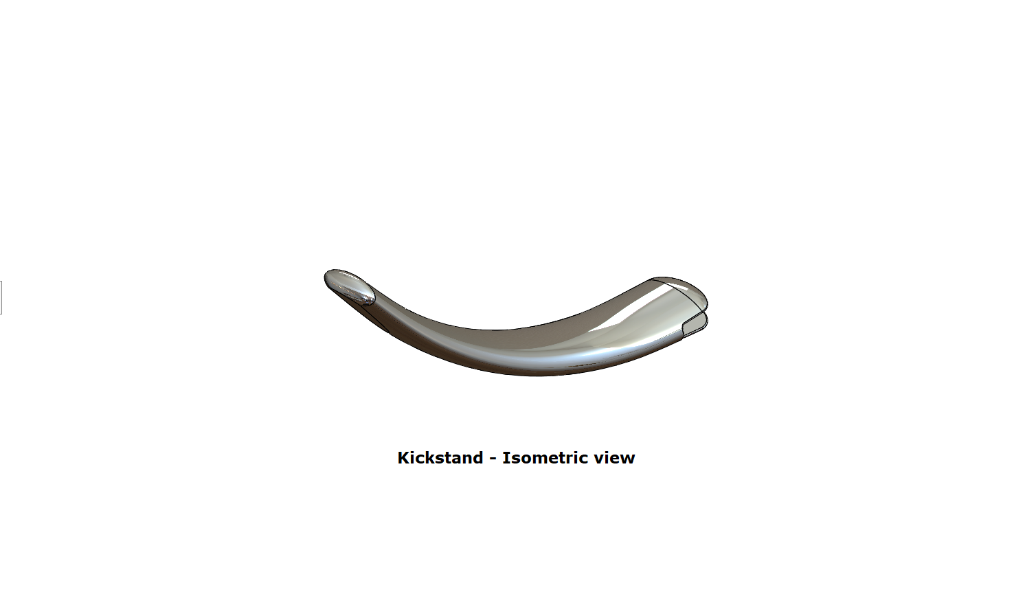
Tools/Features used:
- Lofted Boss/Base: To create a solid feature, it adds material between two or more profiles.
- Dome: This creates a dome shape to the selected face(s) (planar/non-planar).
- Extruded Boss/Base: This feature extrudes an entire sketch or its selected contours in one or both directions (upto a specified distance which can be altered by the user) to give a desired 3D part.
- Extruded Cut: This feature extrudes a sketched profile of a solid model to cut it in one or two directions.
- Split: Multiple bodies can be created from a single part using Split in the existing part or in separate individual parts.
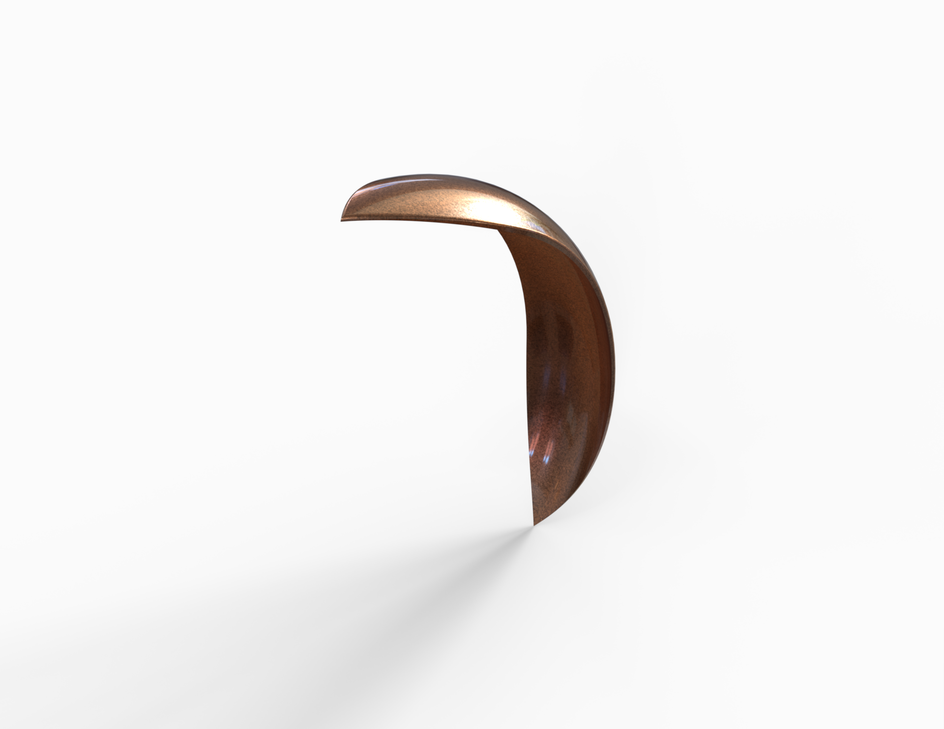
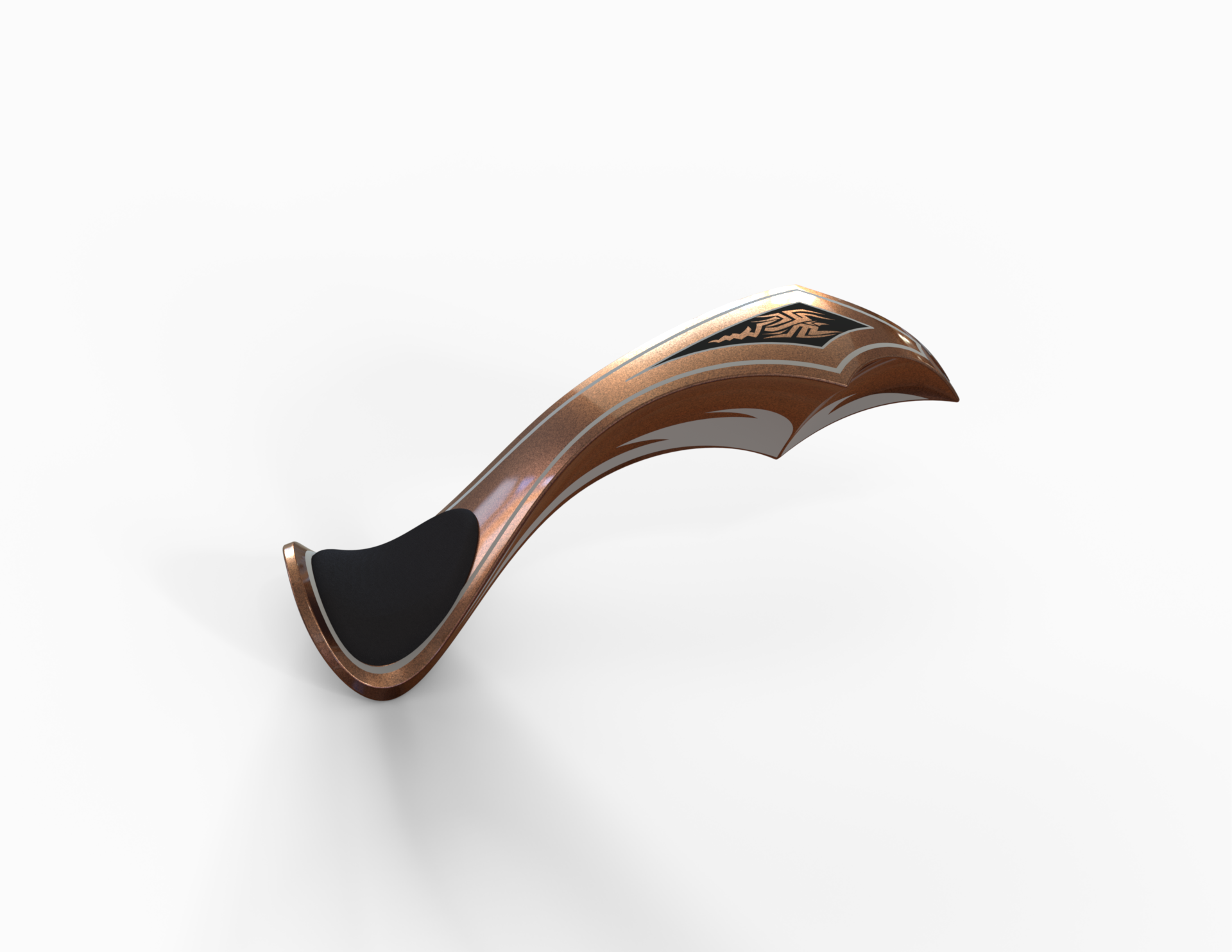
Front Fender
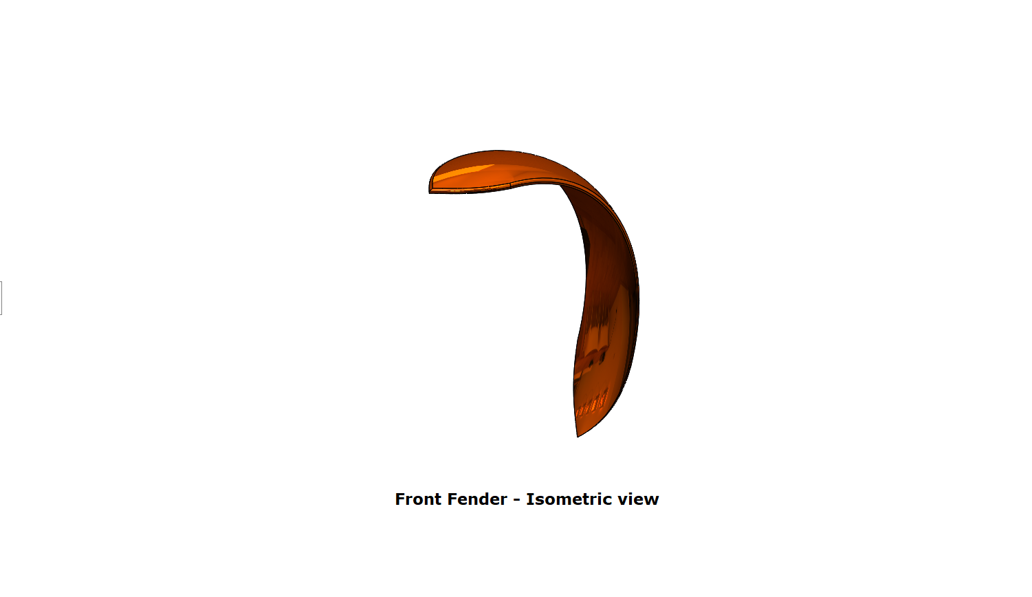
Tools/Features used:
- Revolved Boss/Base:
- Split: Multiple bodies can be created from a single part using Split in the existing part or in separate individual parts.
- Fillet: We can apply this as a sketch tool while creating our sketch or as a feature after a 2D sketch is transformed into a 3D feature. It rounds the corner of two sketch entities at their intersection point creating a tangent arc. When applied as a 3D feature (solid/surface), it creates a rounded internal or external face along one or more edges.
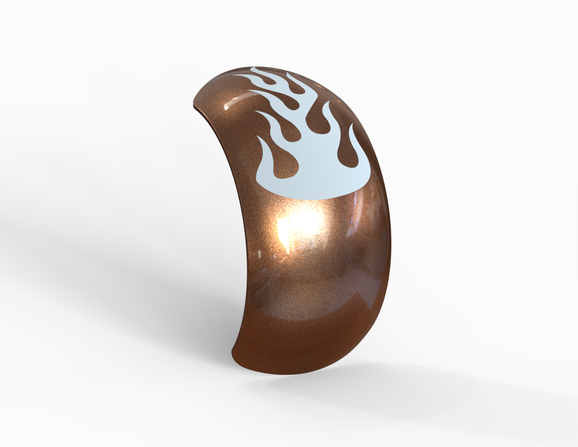
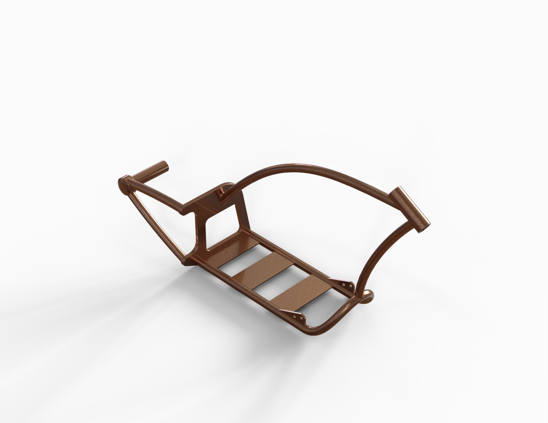
Rear Fender
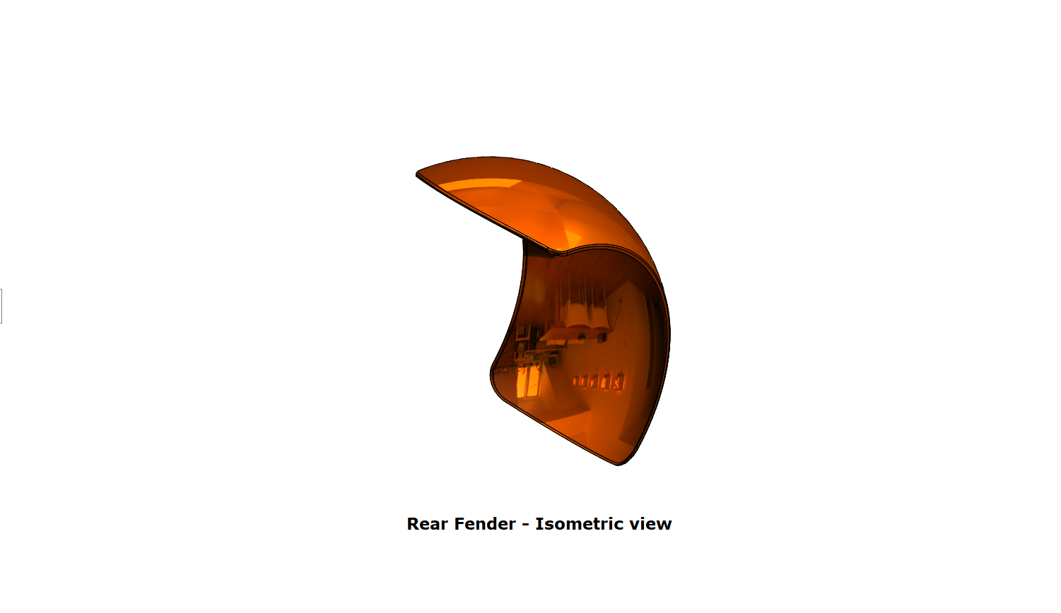
Tools/Features used:
- Revolved Boss/Base: To create a solid feature, a sketch or its selected contours are revolved around an axis.
- Split: Multiple bodies can be created from a single part using Split in the existing part or in separate individual parts.
- Fillet: We can apply this as a sketch tool while creating our sketch or as a feature after a 2D sketch is transformed into a 3D feature. It rounds the corner of two sketch entities at their intersection point creating a tangent arc. When applied as a 3D feature (solid/surface), it creates a rounded internal or external face along one or more edges.
- Shell: A thin-walled feature is created using Shell which removes material from the selected solid body.
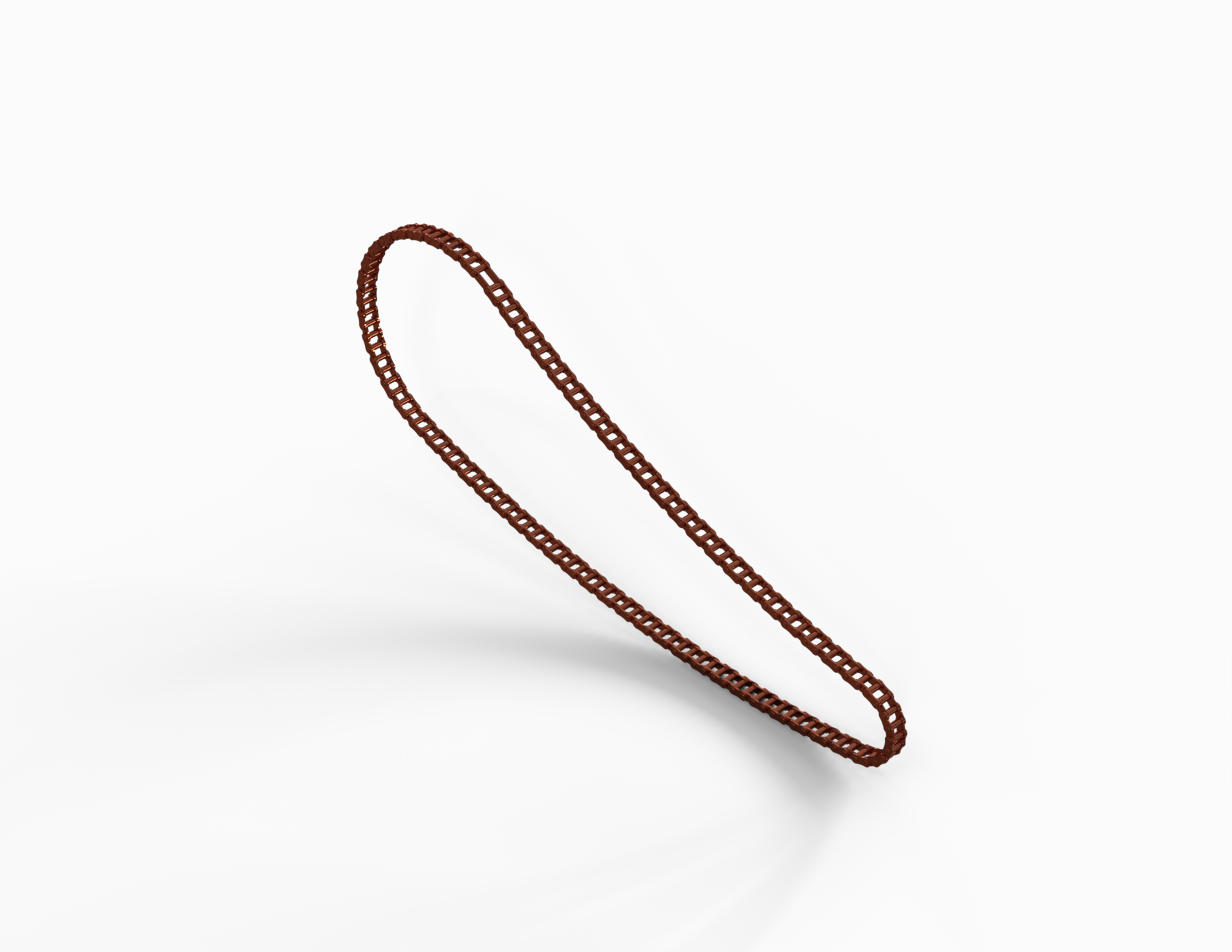
Chain
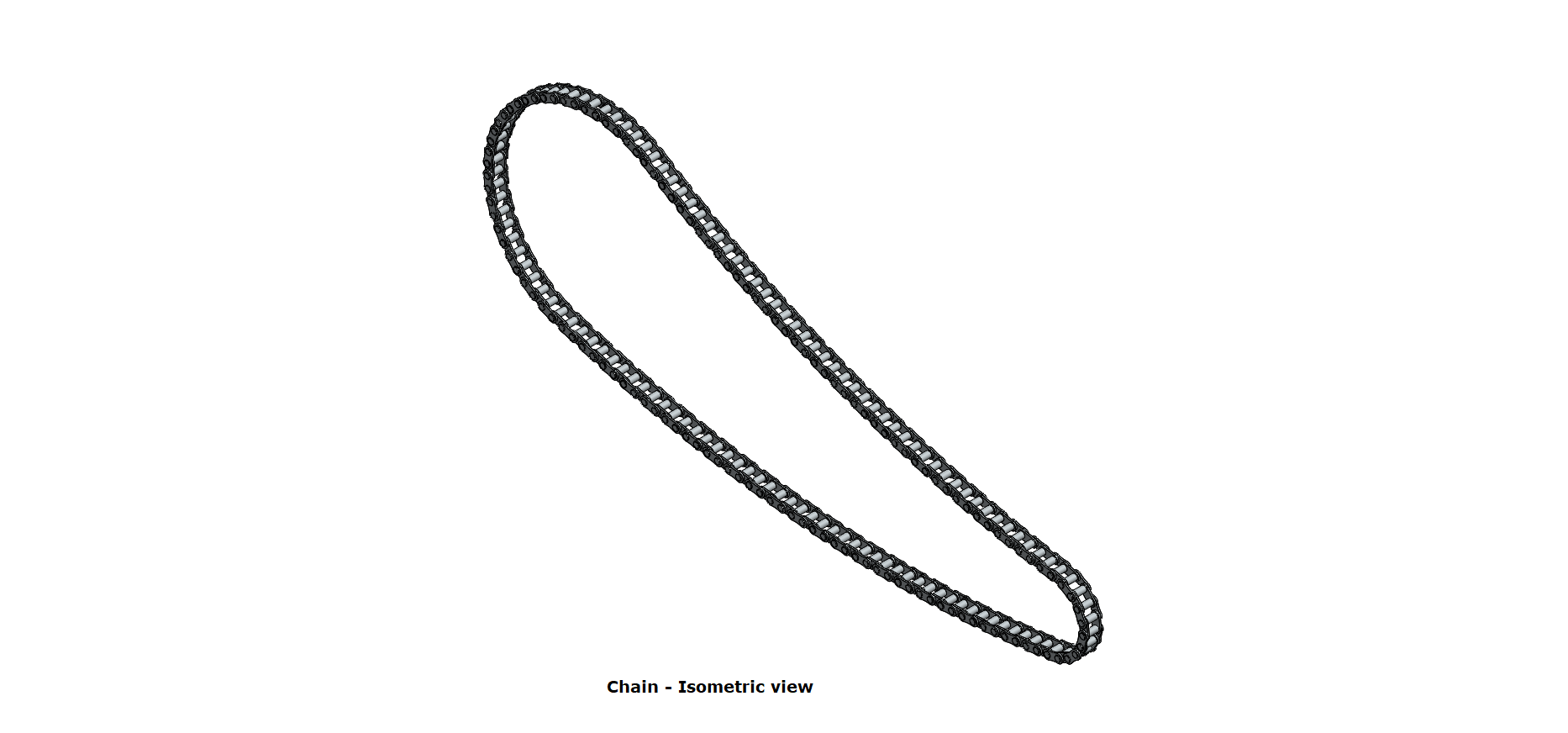
Tools/Features used:
- Extruded Boss/Base: This feature extrudes an entire sketch or its selected contours in one or both directions (upto a specified distance which can be altered by the user) to give a desired 3D part.
- Fillet: We can apply this as a sketch tool while creating our sketch or as a feature after a 2D sketch is transformed into a 3D feature. It rounds the corner of two sketch entities at their intersection point creating a tangent arc. When applied as a 3D feature (solid/surface), it creates a rounded internal or external face along one or more edges.
- Curve Driven Pattern: It creates a pattern of features, faces and bodies based on an existing curve.
- Mirror: This can be used as a sketch tool or as a feature. In sketch mode, it mirrors the selected entities about a reference plane or centerline. When used as a feature on a 3D body, it mirrors the features, faces and bodies about a face or a plane.
- Delete/Keep Body: This simply deletes or keeps one or more solid or surface bodies.
Oil Tank
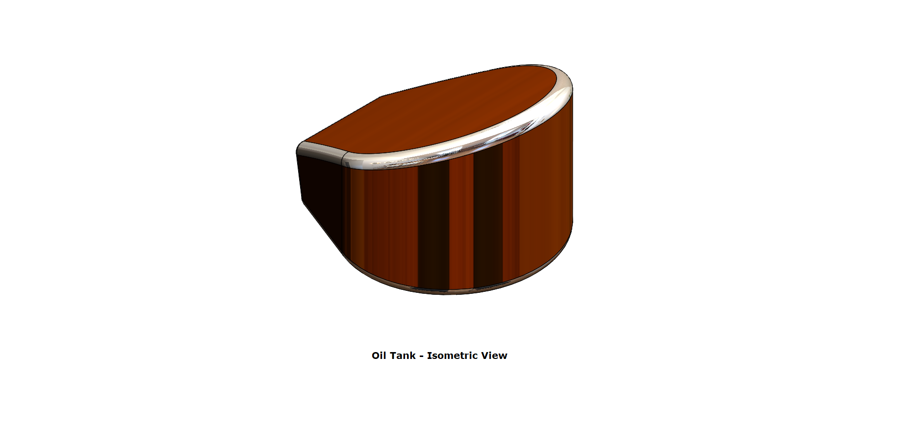
Tools/Features used:
- Extruded Boss/Base: This feature extrudes an entire sketch or its selected contours in one or both directions (upto a specified distance which can be altered by the user) to give a desired 3D part.
- Combine: This feature combines two or more solid bodies.
- Fillet: We can apply this as a sketch tool while creating our sketch or as a feature after a 2D sketch is transformed into a 3D feature. It rounds the corner of two sketch entities at their intersection point creating a tangent arc. When applied as a 3D feature (solid/surface), it creates a rounded internal or external face along one or more edges.
- Shell: A thin-walled feature is created using Shell which removes material from the selected solid body.
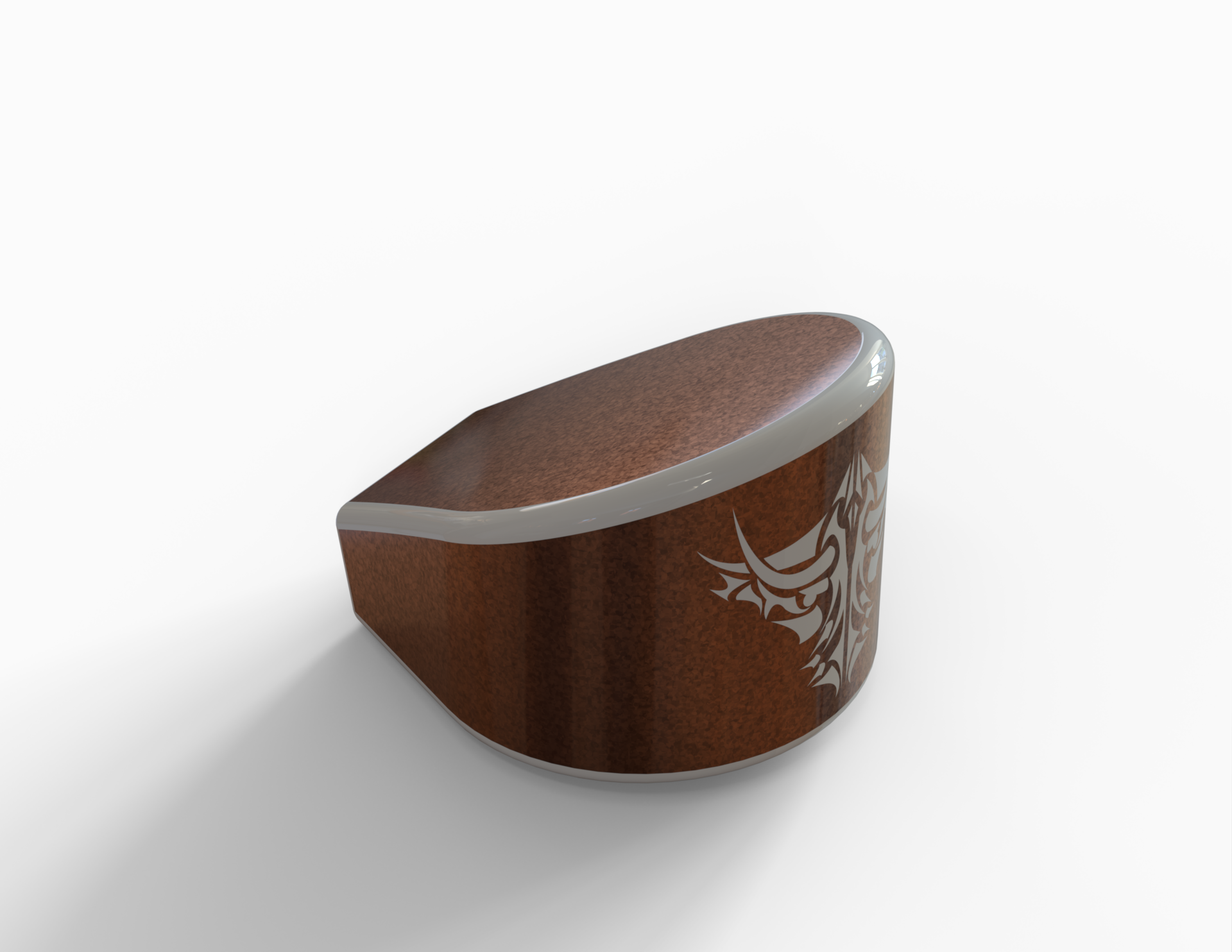
Pedal
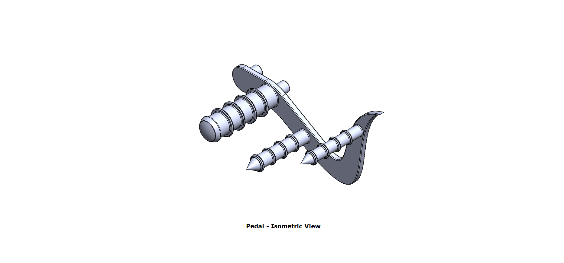
Tools/Features used:
- Extruded Boss/Base: This feature extrudes an entire sketch or its selected contours in one or both directions (upto a specified distance which can be altered by the user) to give a desired 3D part.
- Revolved Boss/Base: To create a solid feature, a sketch or its selected contours are revolved around an axis.
- Dome: This creates a dome shape to the selected face(s) (planar/non-planar).
- Fillet: We can apply this as a sketch tool while creating our sketch or as a feature after a 2D sketch is transformed into a 3D feature. It rounds the corner of two sketch entities at their intersection point creating a tangent arc. When applied as a 3D feature (solid/surface), it creates a rounded internal or external face along one or more edges.
- Chamfer: We can apply this as a sketch tool while creating our sketch or as a feature after a 2D sketch is transformed into a 3D feature. It creates a transitional edge at the intersection of two sketch entities when used as a sketch tool. When used as a feature, it creates a bevel feature along an edge or a vertex.
- Linear Pattern: It creates a pattern of features, faces and bodies in one or two linear directions.
Front Wheel
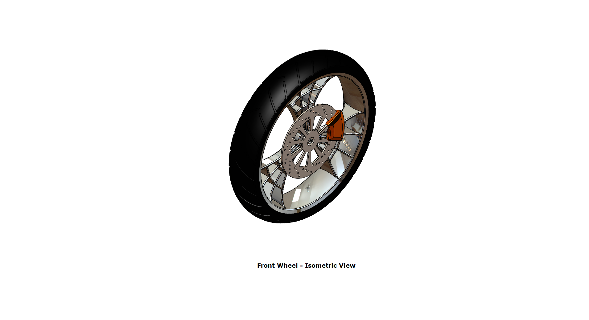
Tools/Features used:
- Revolved Boss/Base: To create a solid feature, a sketch or its selected contours are revolved around an axis.
- Extruded Boss/Base: This feature extrudes an entire sketch or its selected contours in one or both directions (upto a specified distance which can be altered by the user) to give a desired 3D part.
- Extruded Cut: This feature extrudes a sketched profile of a solid model to cut it in one or two directions.
- Revolved Cut: This revolves a sketch profile around an axis to cut a solid body.
- Circular Pattern: It creates a pattern of features, faces and bodies around an axis.
- Combine: This feature combines two or more solid bodies.
- Fillet: We can apply this as a sketch tool while creating our sketch or as a feature after a 2D sketch is transformed into a 3D feature. It rounds the corner of two sketch entities at their intersection point creating a tangent arc. When applied as a 3D feature (solid/surface), it creates a rounded internal or external face along one or more edges.
- Chamfer: We can apply this as a sketch tool while creating our sketch or as a feature after a 2D sketch is transformed into a 3D feature. It creates a transitional edge at the intersection of two sketch entities when used as a sketch tool. When used as a feature, it creates a bevel feature along an edge or a vertex.
Rear Wheel
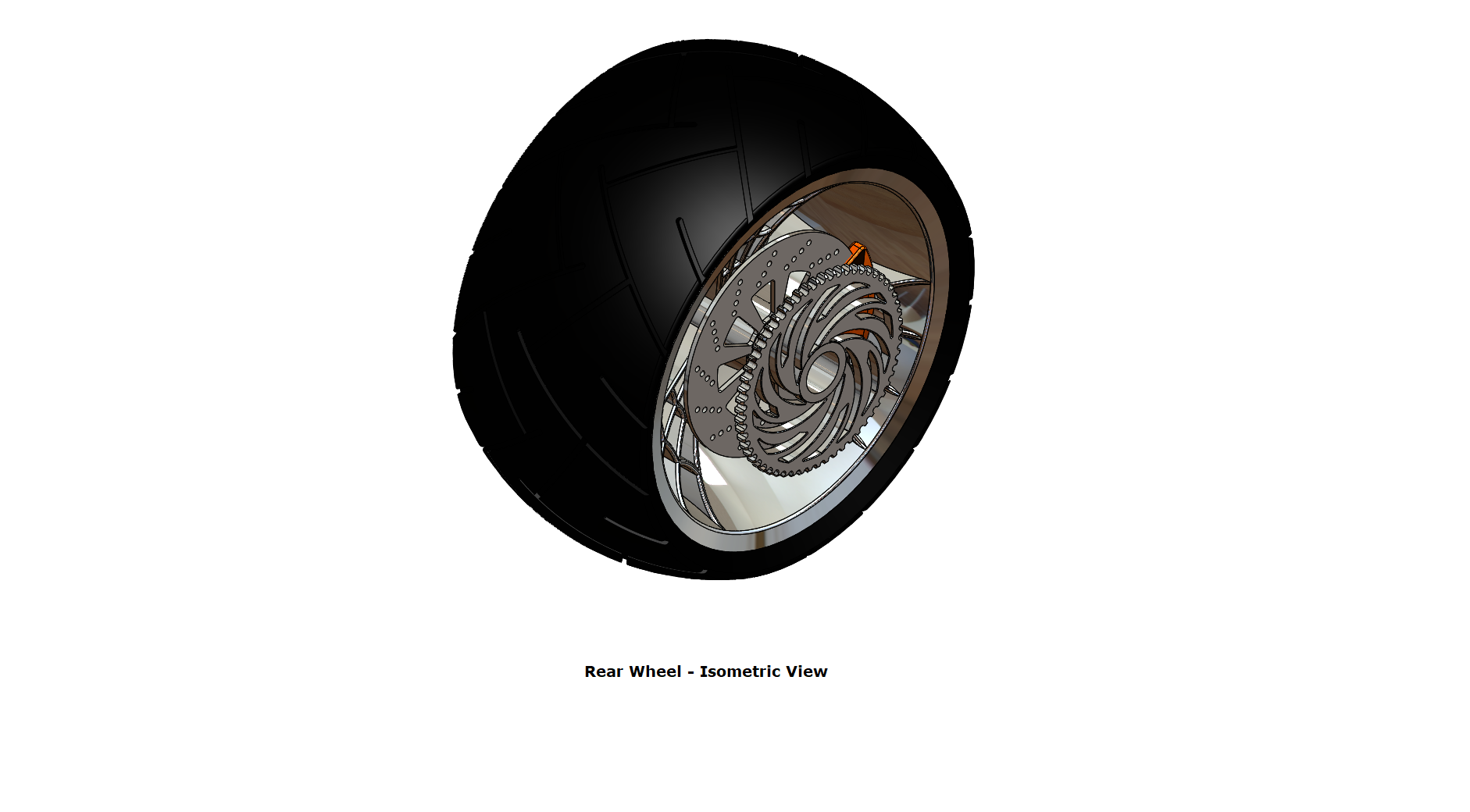
Tools/Features used:
- Revolved Boss/Base: To create a solid feature, a sketch or its selected contours are revolved around an axis.
- Extruded Boss/Base: This feature extrudes an entire sketch or its selected contours in one or both directions (upto a specified distance which can be altered by the user) to give a desired 3D part.
- Extruded Cut: This feature extrudes a sketched profile of a solid model to cut it in one or two directions.
- Revolved Cut: This revolves a sketch profile around an axis to cut a solid body.
- Circular Pattern: It creates a pattern of features, faces and bodies around an axis.
- Combine: This feature combines two or more solid bodies.
- Fillet: We can apply this as a sketch tool while creating our sketch or as a feature after a 2D sketch is transformed into a 3D feature. It rounds the corner of two sketch entities at their intersection point creating a tangent arc. When applied as a 3D feature (solid/surface), it creates a rounded internal or external face along one or more edges.
- Chamfer: We can apply this as a sketch tool while creating our sketch or as a feature after a 2D sketch is transformed into a 3D feature. It creates a transitional edge at the intersection of two sketch entities when used as a sketch tool. When used as a feature, it creates a bevel feature along an edge or a vertex.
Front Fork
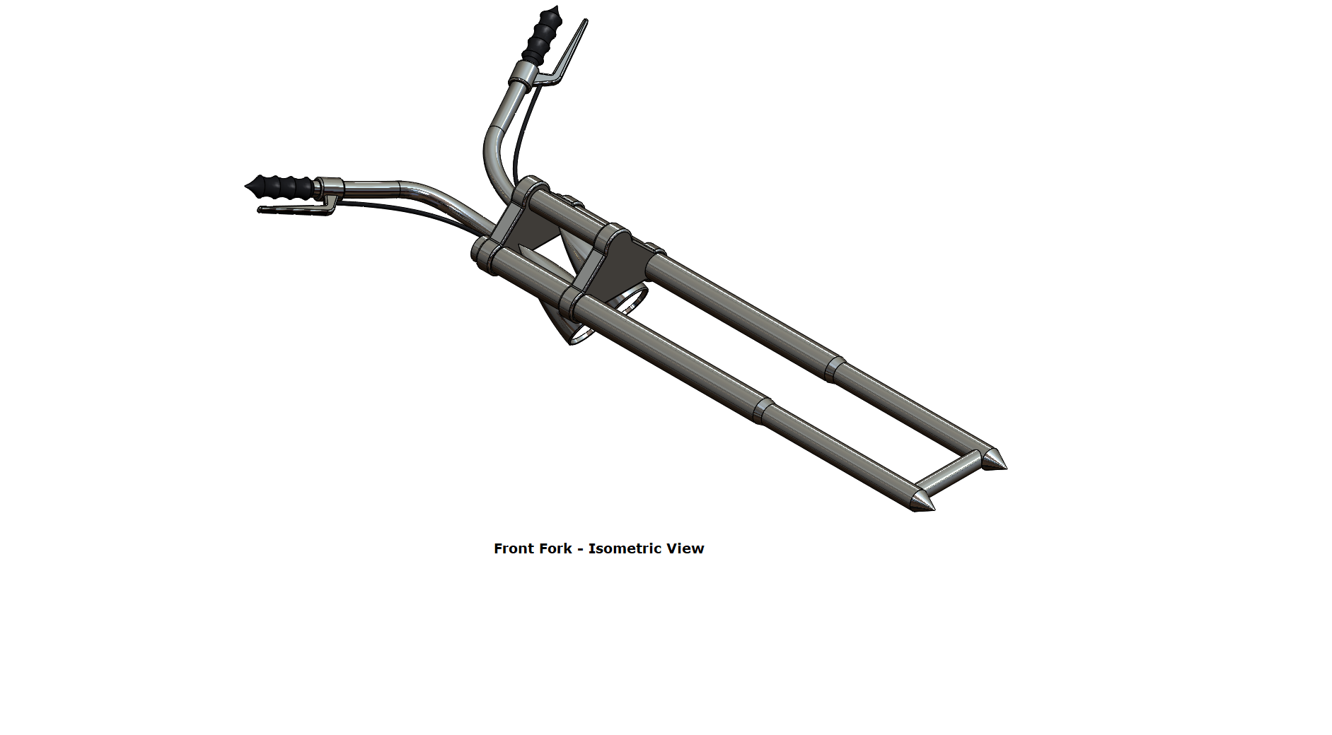
Tools/Features used:
- Revolved Boss/Base: To create a solid feature, a sketch or its selected contours are revolved around an axis.
- Extruded Boss/Base: This feature extrudes an entire sketch or its selected contours in one or both directions (upto a specified distance which can be altered by the user) to give a desired 3D part.
- Fillet: We can apply this as a sketch tool while creating our sketch or as a feature after a 2D sketch is transformed into a 3D feature. It rounds the corner of two sketch entities at their intersection point creating a tangent arc. When applied as a 3D feature (solid/surface), it creates a rounded internal or external face along one or more edges.
- Linear Pattern: It creates a pattern of features, faces and bodies in one or two linear directions.
- Extruded Cut: This feature extrudes a sketched profile of a solid model to cut it in one or two directions.
- Dome: This creates a dome shape to the selected face(s) (planar/non-planar).
- Revolved Cut: This revolves a sketch profile around an axis to cut a solid body.
- Move/Copy Body: This simply moves, copies and rotates one or more solid or surface bodies.
- Projected Curve: It projects a sketched curve onto a face or sketch.
- Swept Boss/Base: Sweeps a closed profile along an open or closed path to create a solid feature.
- Reference Plane: This allows us to add a reference plane at the selected position.
- Mirror: This can be used as a sketch tool or as a feature. In sketch mode, it mirrors the selected entities about a reference plane or centerline. When used as a feature on a 3D body, it mirrors the features, faces and bodies about a face or a plane.
- Combine: This feature combines two or more solid bodies.
Chassis
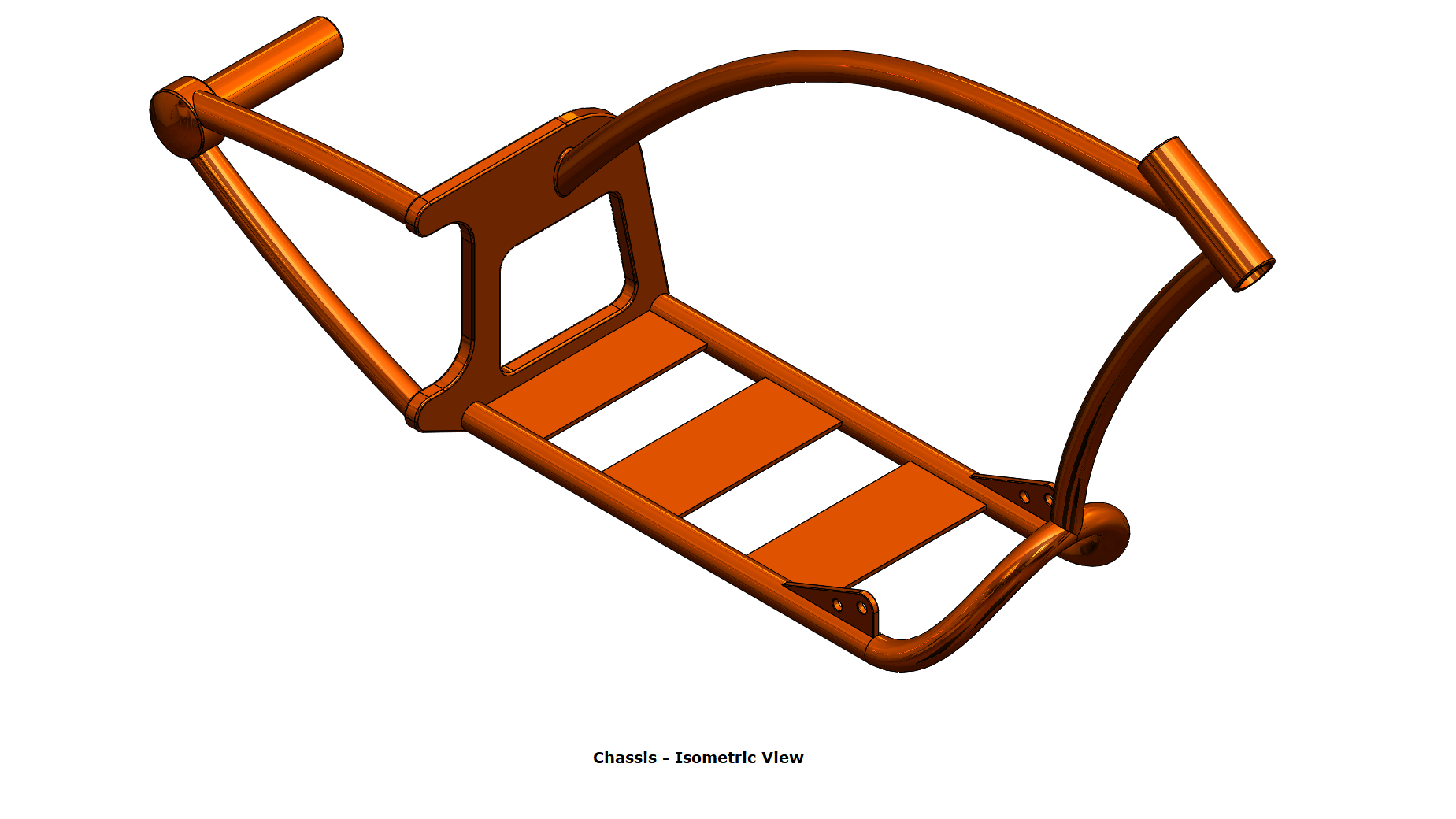
Tools/Features used:
- Sketch Picture: This enables the user to add an image file to a sketch background as a reference.
- Projected Curve: It projects a sketched curve onto a face or sketch.
- Swept Boss/Base: Sweeps a closed profile along an open or closed path to create a solid feature.
- Extruded Boss/Base: This feature extrudes an entire sketch or its selected contours in one or both directions (upto a specified distance which can be altered by the user) to give a desired 3D part.
- Extruded Cut: This feature extrudes a sketched profile of a solid model to cut it in one or two directions.
- Dome: This creates a dome shape to the selected face(s) (planar/non-planar).
- Fillet: We can apply this as a sketch tool while creating our sketch or as a feature after a 2D sketch is transformed into a 3D feature. It rounds the corner of two sketch entities at their intersection point creating a tangent arc. When applied as a 3D feature (solid/surface), it creates a rounded internal or external face along one or more edges.
- Chamfer: We can apply this as a sketch tool while creating our sketch or as a feature after a 2D sketch is transformed into a 3D feature. It creates a transitional edge at the intersection of two sketch entities when used as a sketch tool. When used as a feature, it creates a bevel feature along an edge or a vertex.
- Mirror: This can be used as a sketch tool or as a feature. In sketch mode, it mirrors the selected entities about a reference plane or centerline. When used as a feature on a 3D body, it mirrors the features, faces and bodies about a face or a plane.
- Reference Plane: This allows us to add a reference plane at the selected position.
- Revolved Boss/Base: To create a solid feature, a sketch or its selected contours are revolved around an axis.
- Combine: This feature combines two or more solid bodies.
- Split: Multiple bodies can be created from a single part using Split in the existing part or in separate individual parts.
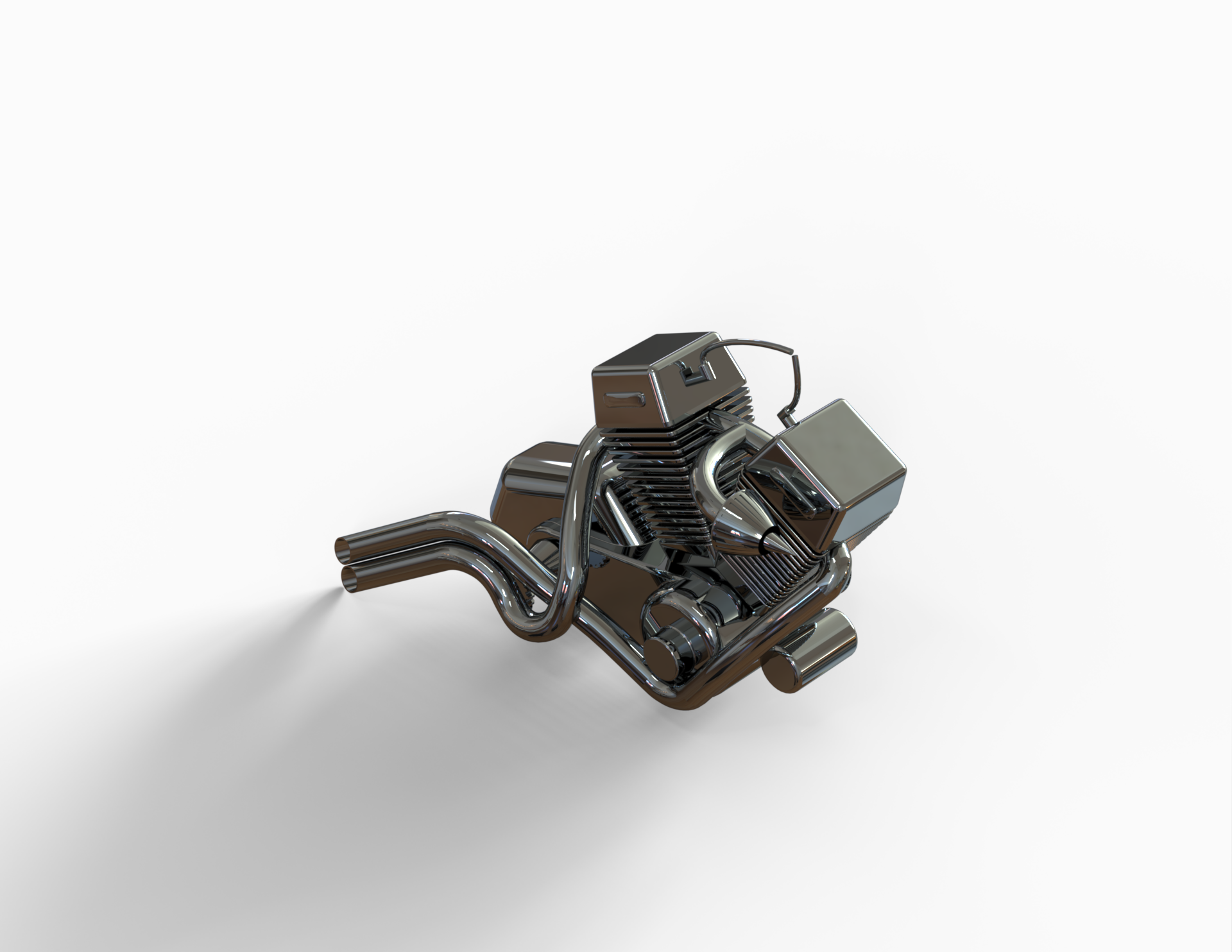
Engine
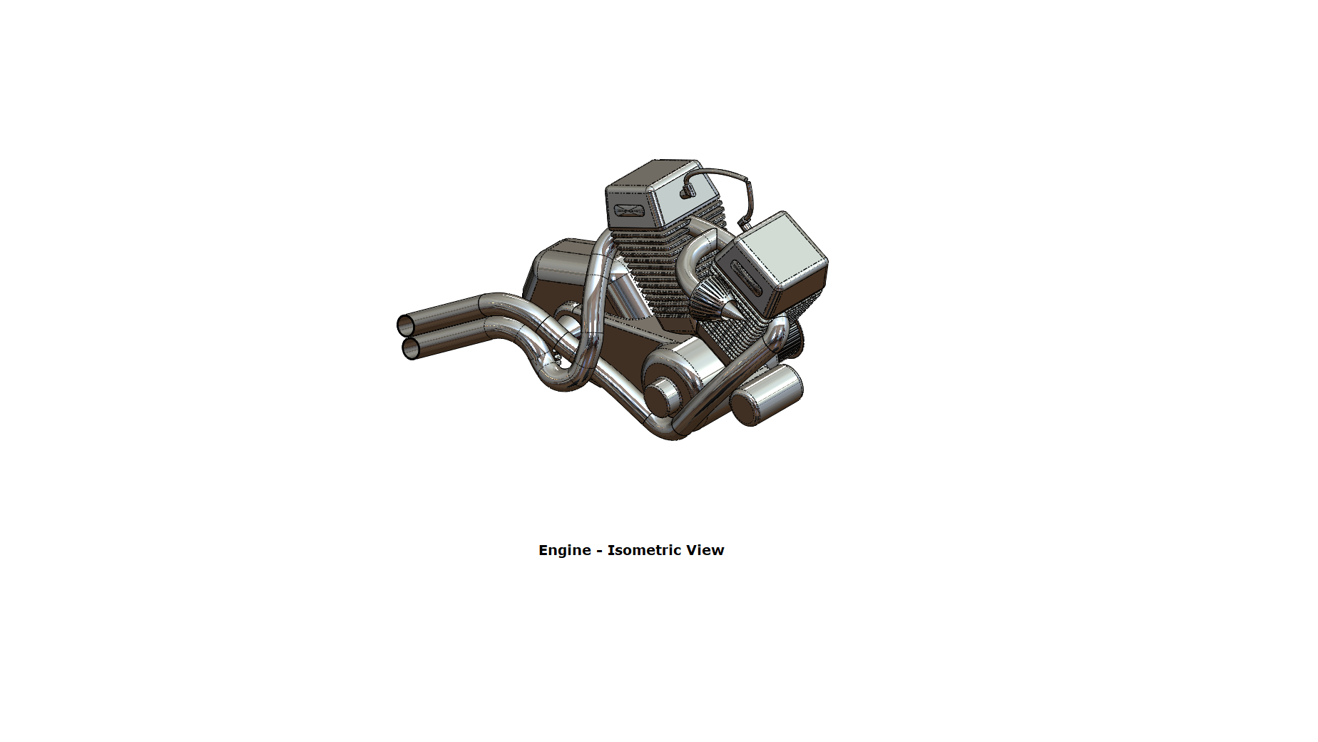
Tools/Features used:
- Sketch Picture: This enables the user to add an image file to a sketch background as a reference.
- Extruded Boss/Base: This feature extrudes an entire sketch or its selected contours in one or both directions (upto a specified distance which can be altered by the user) to give a desired 3D part.
- Fillet: We can apply this as a sketch tool while creating our sketch or as a feature after a 2D sketch is transformed into a 3D feature. It rounds the corner of two sketch entities at their intersection point creating a tangent arc. When applied as a 3D feature (solid/surface), it creates a rounded internal or external face along one or more edges.
- Revolved Boss/Base: To create a solid feature, a sketch or its selected contours are revolved around an axis.
- Reference Plane: This allows us to add a reference plane at the selected position.
- Circular Pattern: It creates a pattern of features, faces and bodies around an axis.
- Dome: This creates a dome shape to the selected face(s) (planar/non-planar).
- Extruded Cut: This feature extrudes a sketched profile of a solid model to cut it in one or two directions.
- Chamfer: We can apply this as a sketch tool while creating our sketch or as a feature after a 2D sketch is transformed into a 3D feature. It creates a transitional edge at the intersection of two sketch entities when used as a sketch tool. When used as a feature, it creates a bevel feature along an edge or a vertex.
- Linear Pattern: It creates a pattern of features, faces and bodies in one or two linear directions.
- Mirror: This can be used as a sketch tool or as a feature. In sketch mode, it mirrors the selected entities about a reference plane or centerline. When used as a feature on a 3D body, it mirrors the features, faces and bodies about a face or a plane.
- Swept Boss/Base: Sweeps a closed profile along an open or closed path to create a solid feature.
- Combine: This feature combines two or more solid bodies.
- Projected Curve: It projects a sketched curve onto a face or sketch.
- Composite Curve: It sketches a single curve by combining selected edges and curves.
- Split: Multiple bodies can be created from a single part using Split in the existing part or in separate individual parts.
Gas Tank
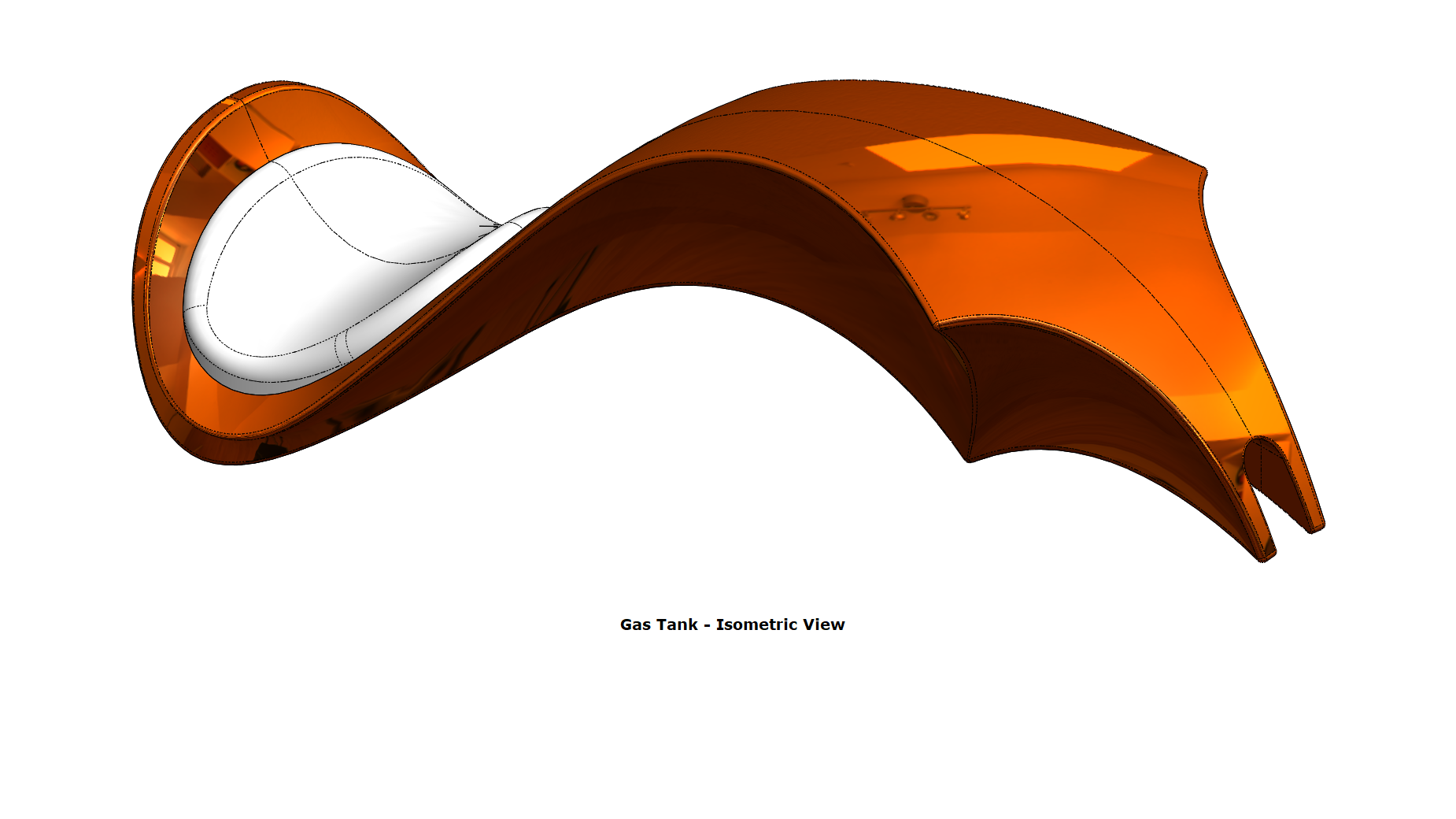
Tools/Features used:
- Sketch Picture: This enables the user to add an image file to a sketch background as a reference.
- Reference Plane: This allows us to add a reference plane at the selected position.
- Swept Surface: It sweeps an open or closed profile along an open or closed path to create a surface feature.
- Trim Surface: It trims a surface at the intersection of two surfaces or, at the intersection of a surface and a plane or a sketch.
- Projected Curve: It projects a sketched curve onto a face or sketch.
- Lofted Surface: It creates a lofted surface between two or more profiles.
- Boundary Surface: This creates a boundary surface between profiles in two directions.
- Mirror: This can be used as a sketch tool or as a feature. In sketch mode, it mirrors the selected entities about a reference plane or centerline. When used as a feature on a 3D body, it mirrors the features, faces and bodies about a face or a plane.
- Knit Surface: It is a knitting operation to combine two or more adjacent , non-intersecting surfaces together.
- Split Line Curve: Multiple separate faces are created by projecting a sketch to curved or planar faces.
- Extruded Surface: This is used to create an extruded surface.
- Fillet: We can apply this as a sketch tool while creating our sketch or as a feature after a 2D sketch is transformed into a 3D feature. It rounds the corner of two sketch entities at their intersection point creating a tangent arc. When applied as a 3D feature (solid/surface), it creates a rounded internal or external face along one or more edges.
- Swept Cut: It cuts a solid body by sweeping a closed profile along an open or closed path.
- Shell: A thin-walled feature is created using Shell which removes material from the selected solid body.
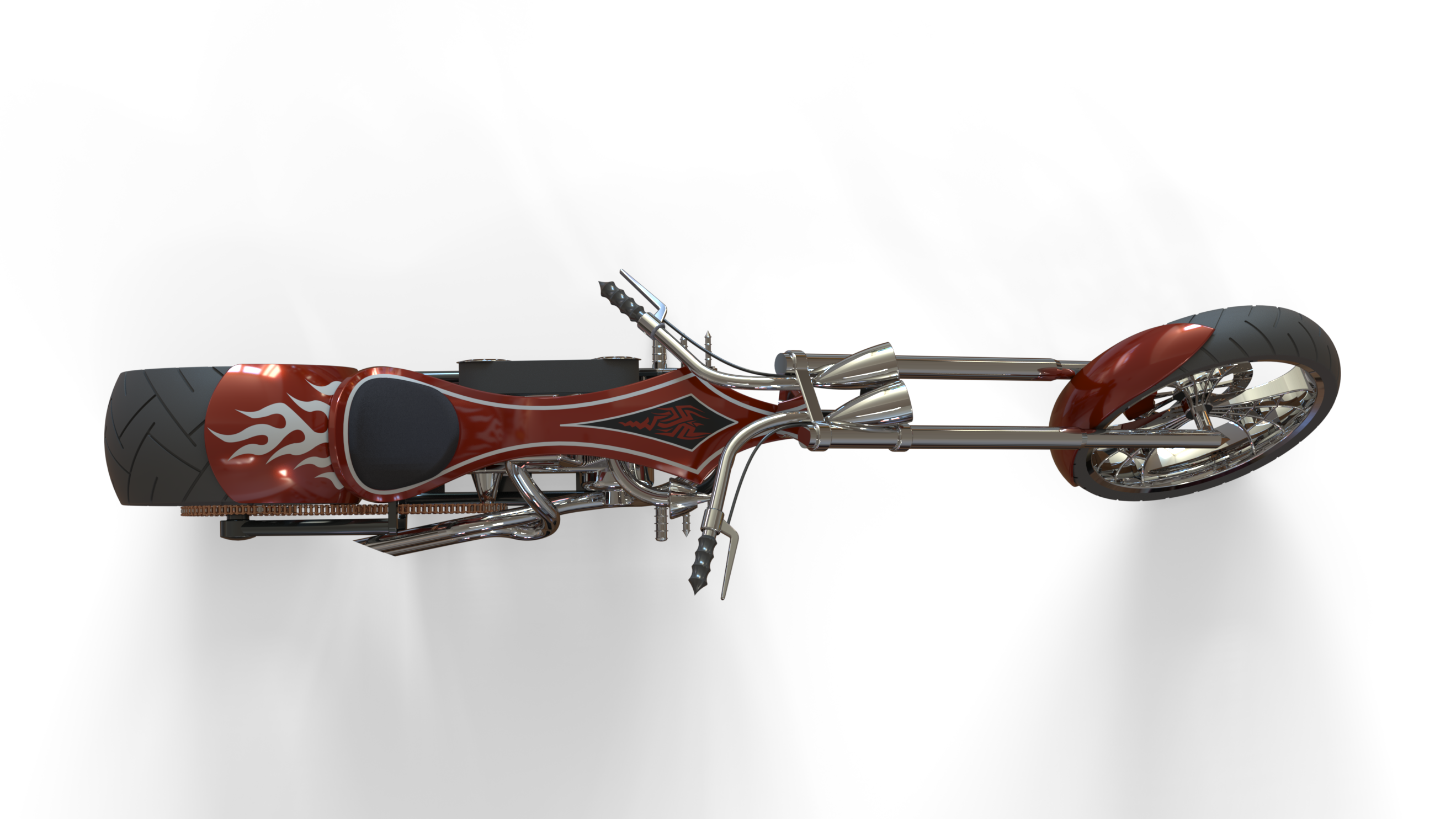
Assembly Model View Images
Front View

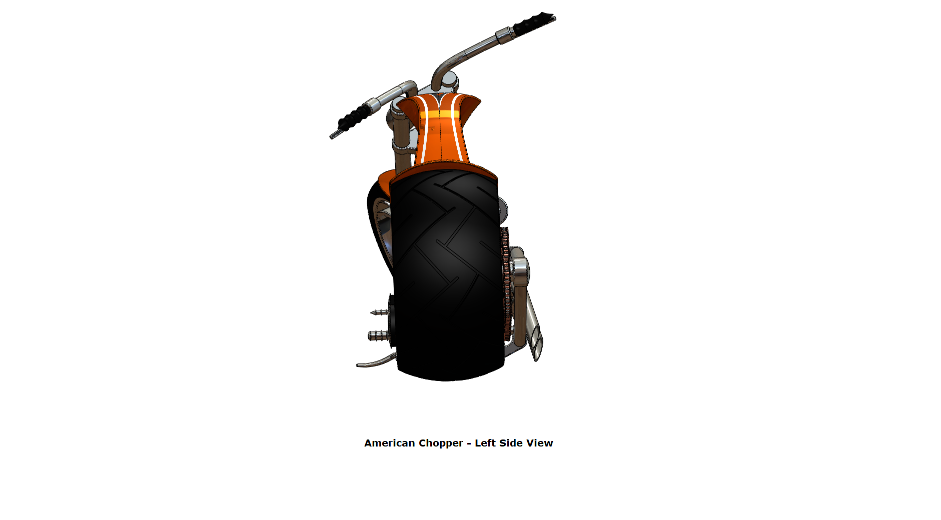
Left Side View
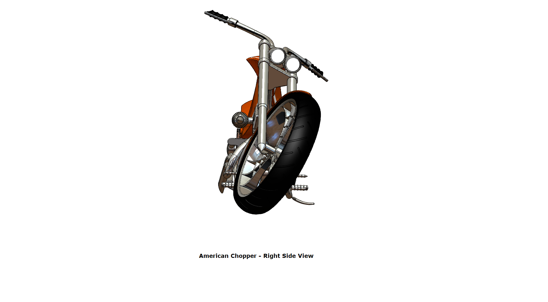
Right Side View
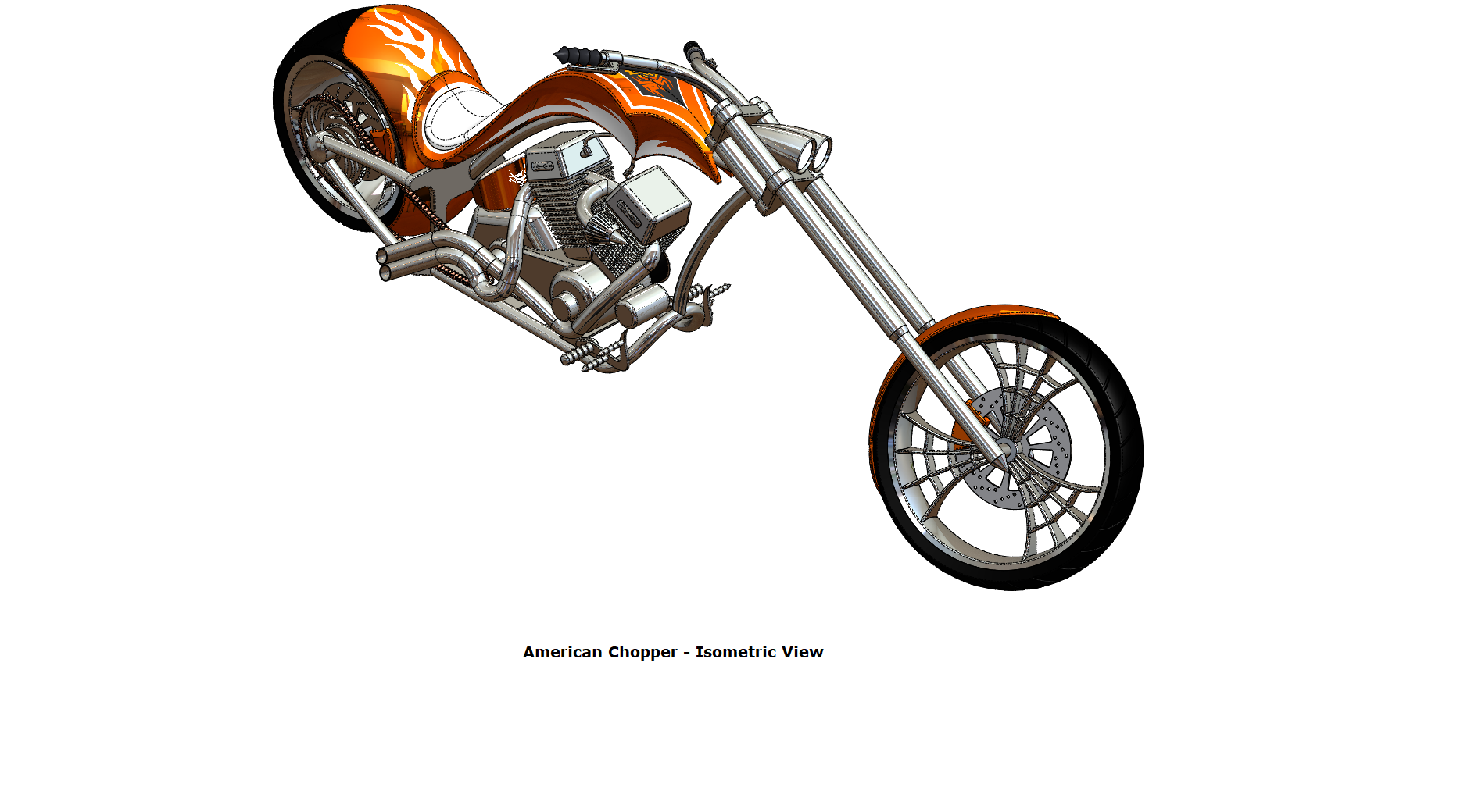
Isometric View
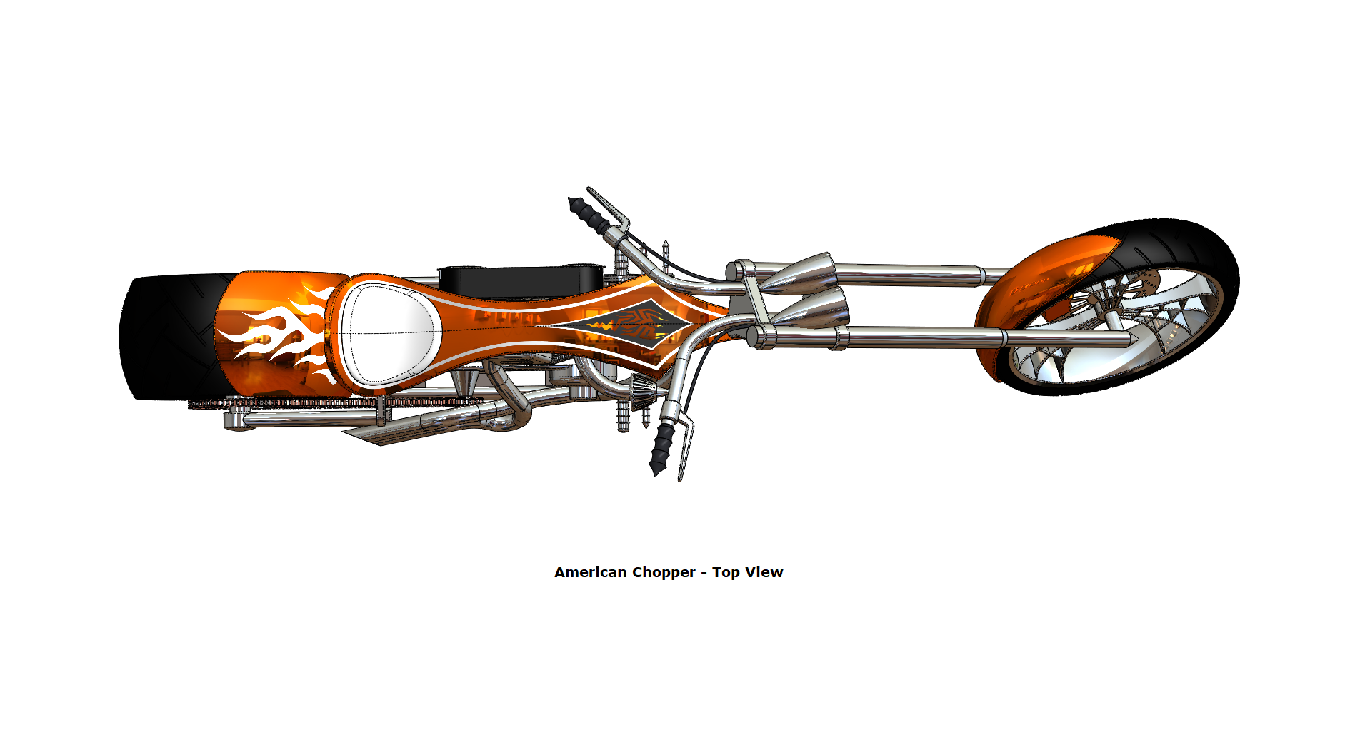
Top View
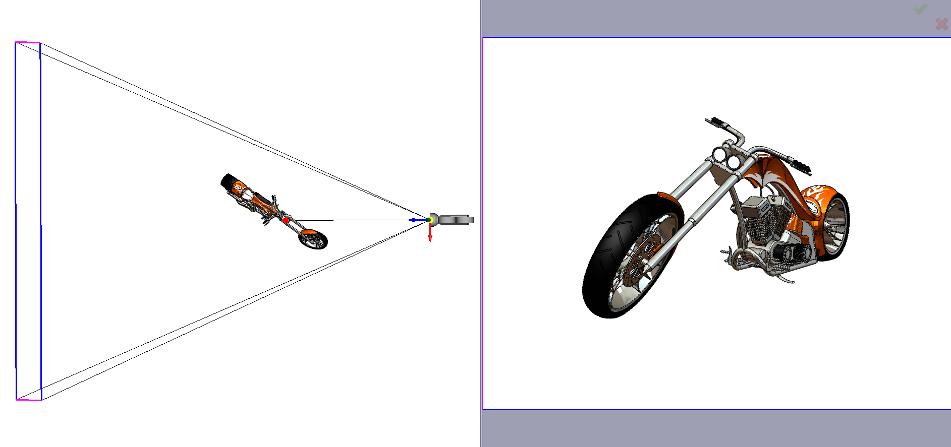
Camera Setup
Rendered Images - Assembly Model & Individual Parts
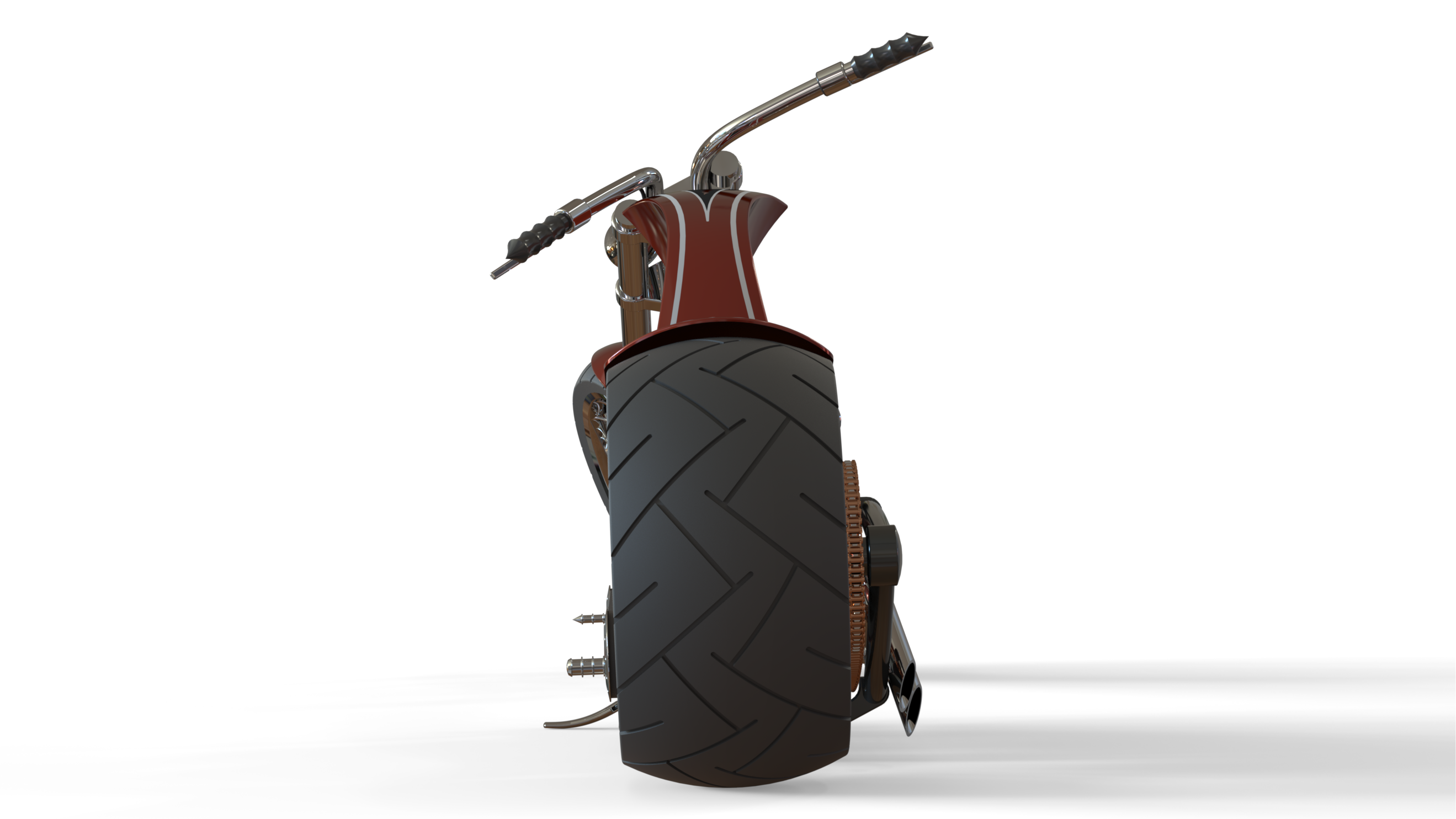
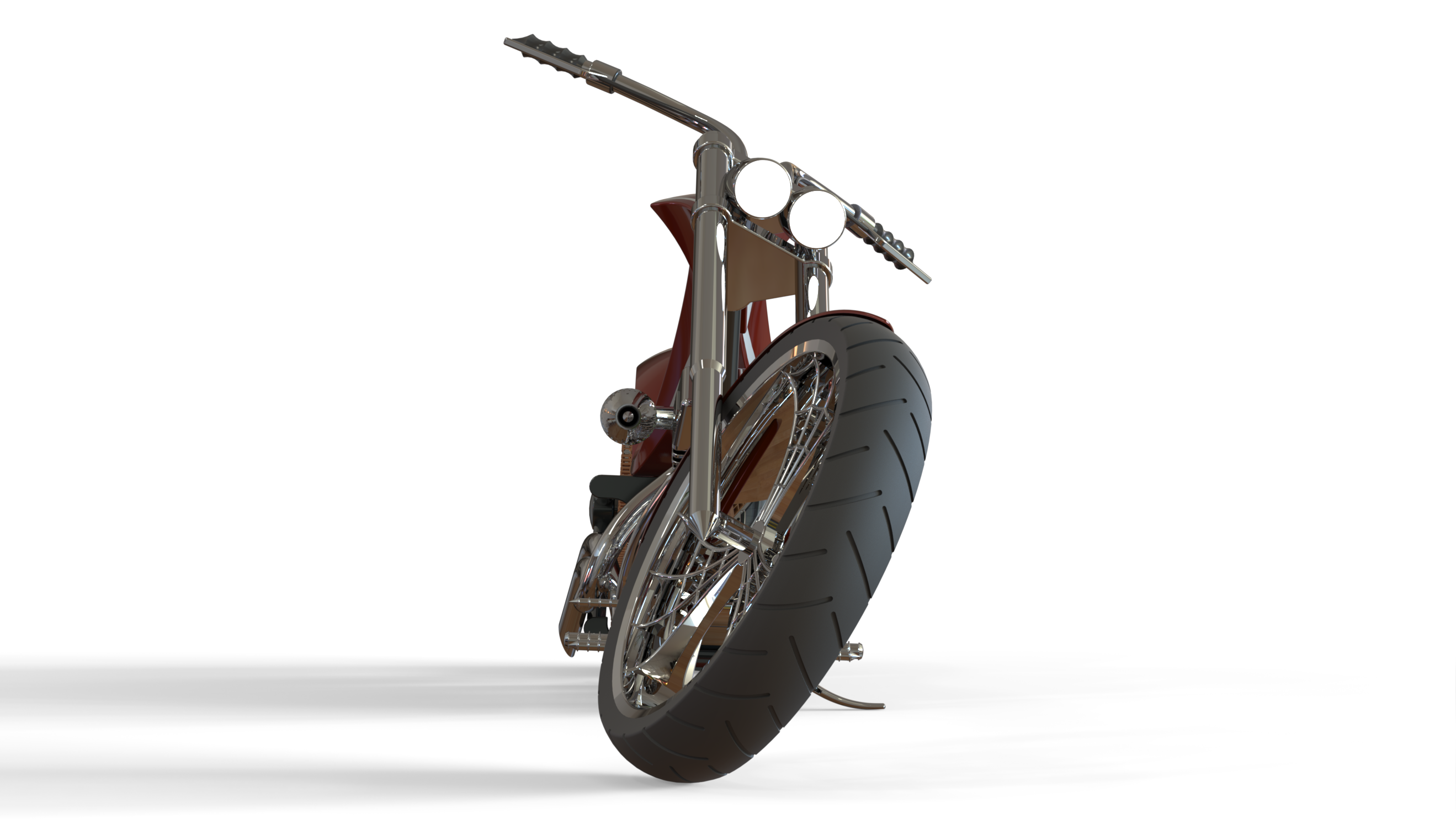
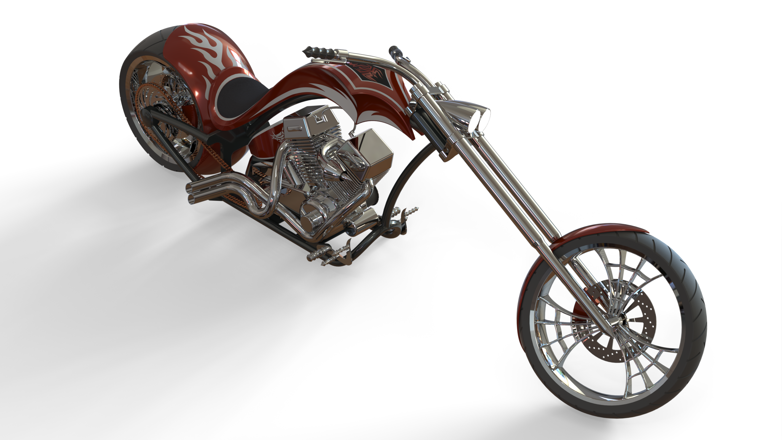
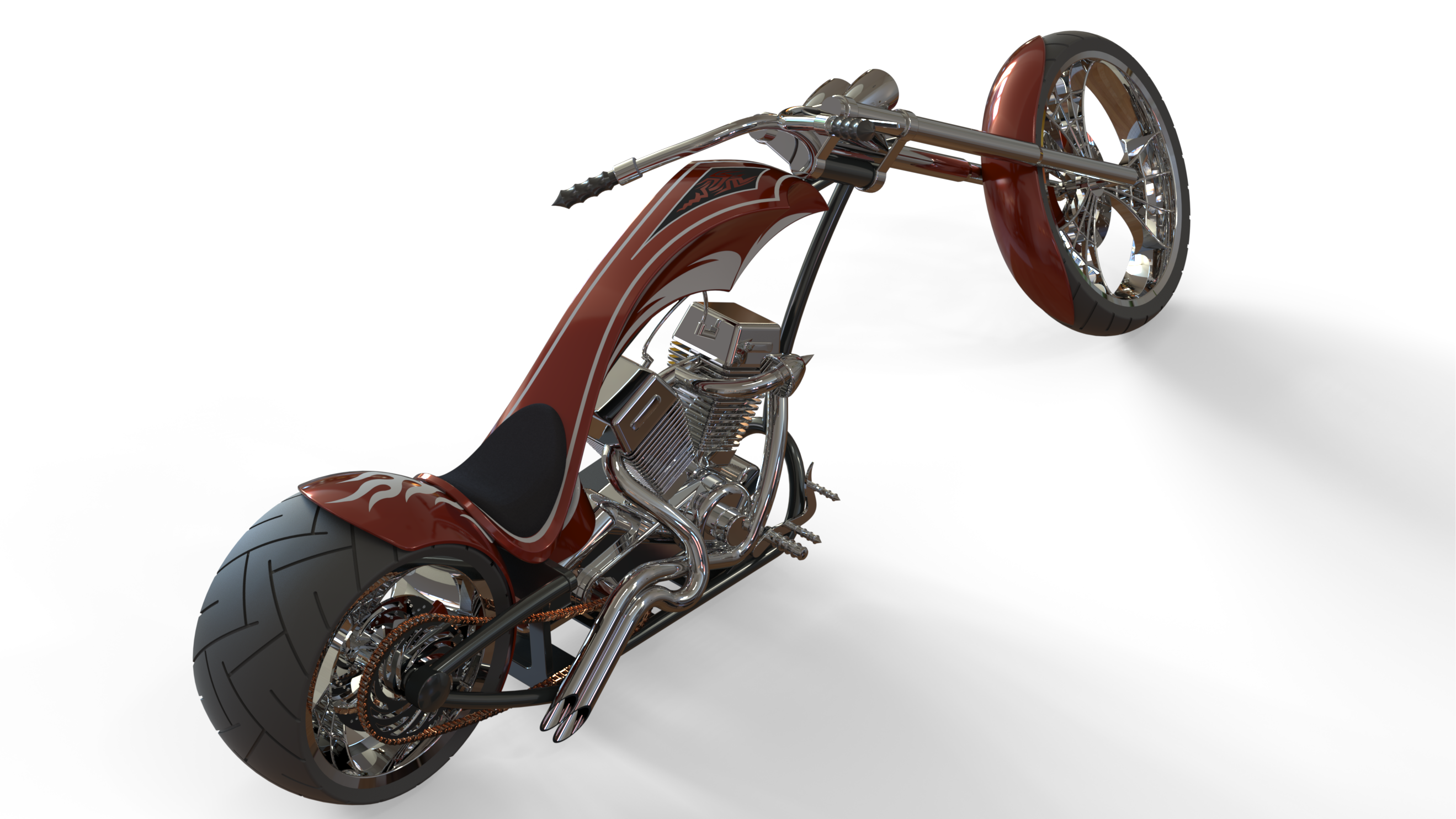
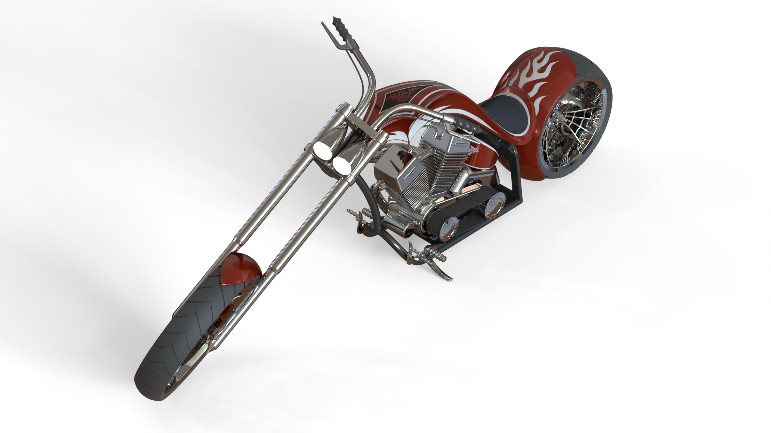
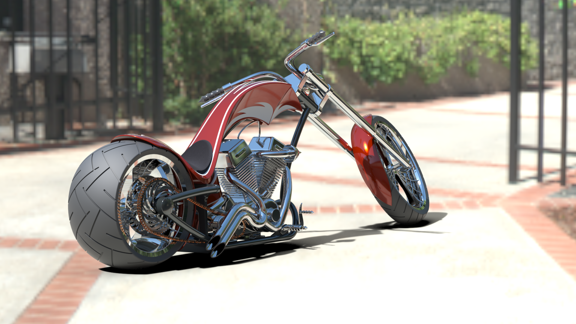
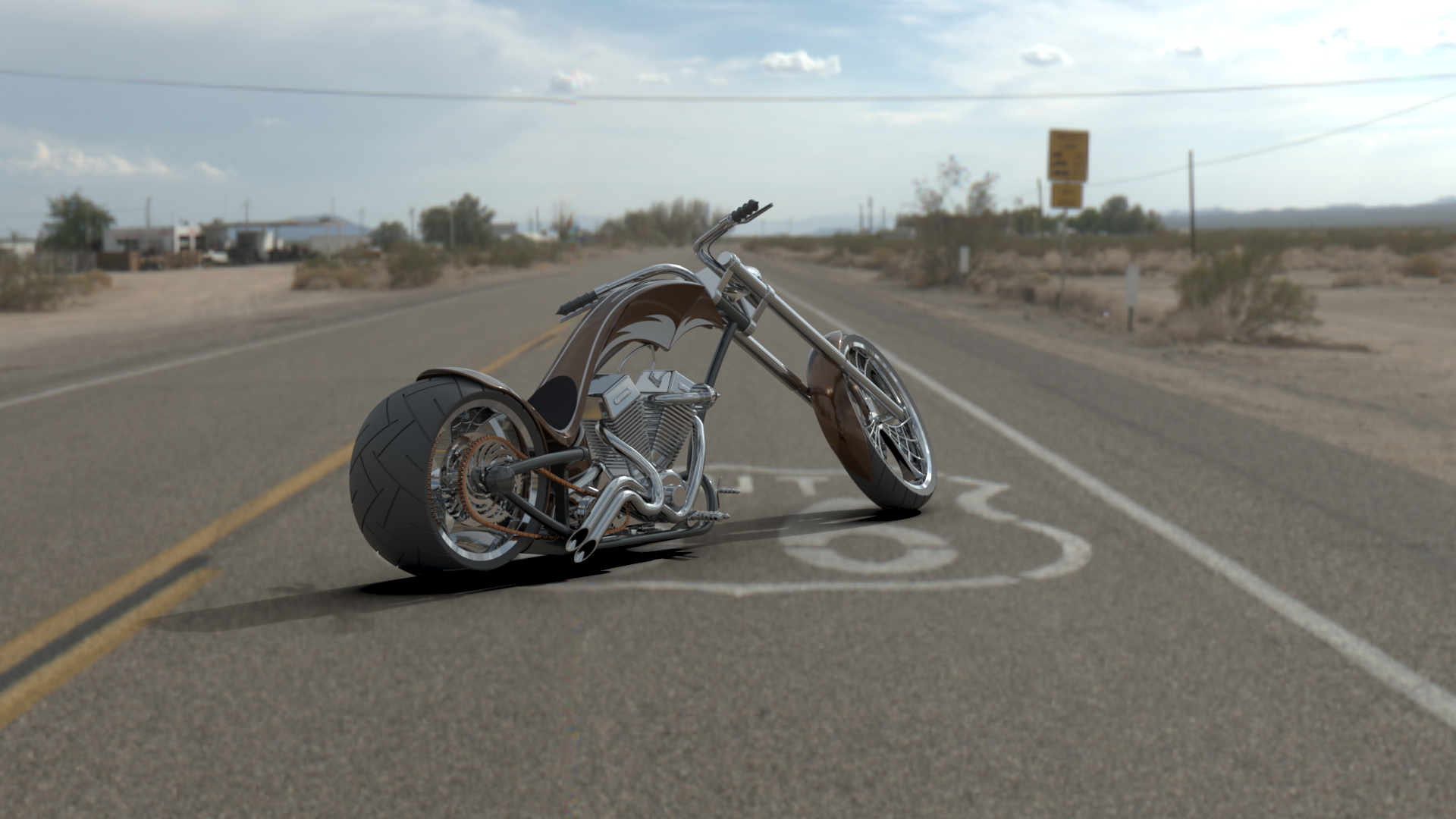
American Chopper Final Render
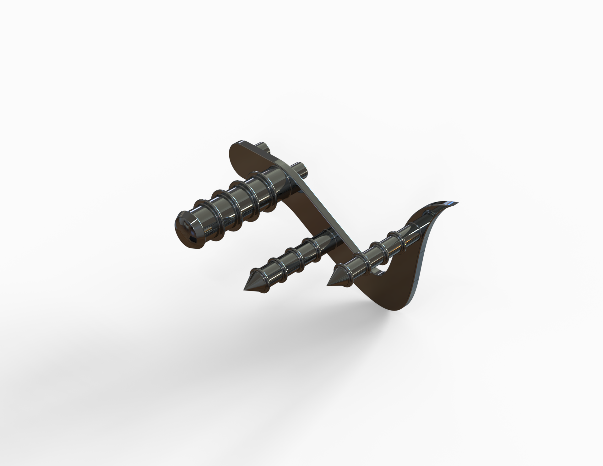
Transmission Belt
Kickstand
Front Fender
Rear Fender
Chain
Oil Tank
Pedal
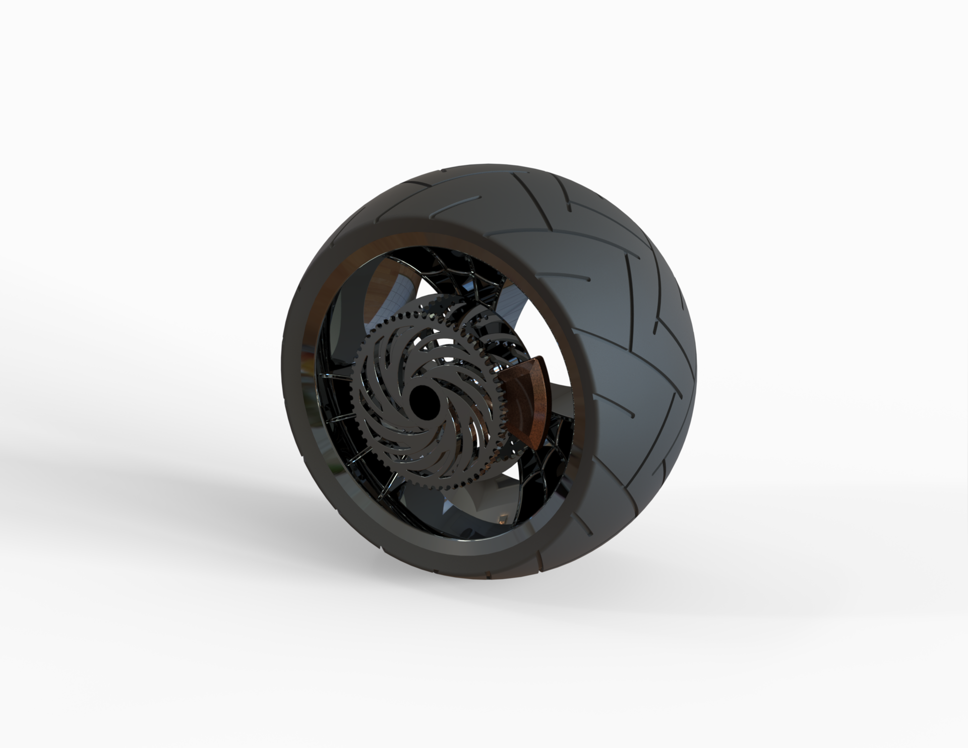
Front Wheel
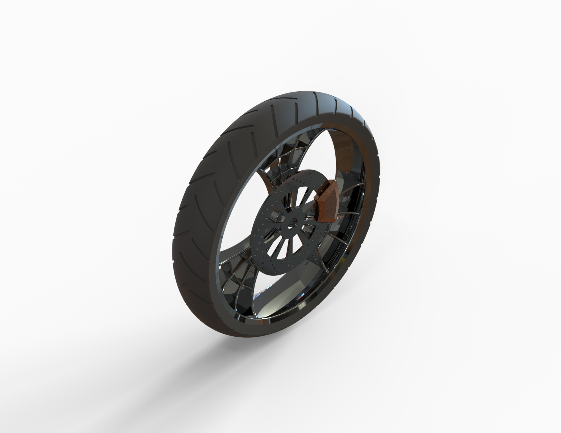
Rear Wheel
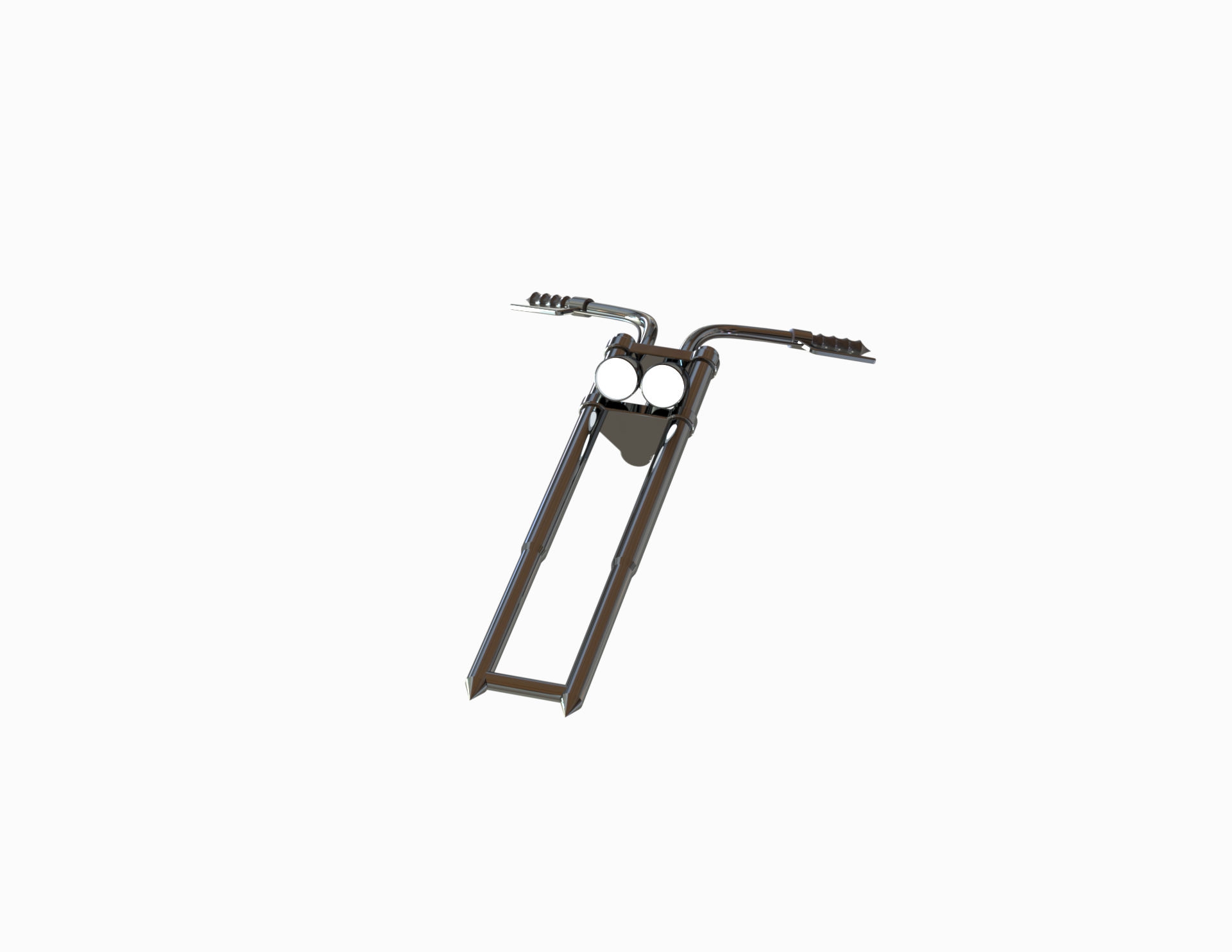
Front Fork
Chassis
Engine
Gas Tank
Conclusion
The practical training on the entire exercise explained above could facilitate us to understand the basic concepts of part modelling and assembly modelling in SolidWorks to design the American Chopper. We also learnt to set up the camera, play with the appearances of different parts and experiment with the scene setup in SolidWorks Visualize to generate a beautiful render of this American Chopper by making some tweaks with object orientation, lighting and other effects that added to the realistic look of the final render.
Best,
Hriday Modgil
Leave a comment
Thanks for choosing to leave a comment. Please keep in mind that all the comments are moderated as per our comment policy, and your email will not be published for privacy reasons. Please leave a personal & meaningful conversation.
Other comments...
Be the first to add a comment
Read more Projects by Hriday Modgil (3)
Football Cube on Wheels
Football Cube on Wheels - Final Project Objective The objective of this SolidWorks Project titled “Football Cube on Wheels” is to design a Trailer Truck with a cubical machine called F-Cube (related to Football), mounted on its Trailer. The idea has been taken from my past job experience where…

30 Jan 2021 09:50 AM IST
Assembly of Yacht
Sunseeker Predator Yacht - Assembly & Render Objective The objective of this project is solely aimed at applying all surface modelling tools in designing a part(s) and then use the surface as reference to assemble the parts of the Sunseeker Predator Yacht in SolidWorks. Introduction In this project, we…
25 Dec 2020 08:29 PM IST
Photo Realistic Rendering
The American Chopper - Assembly & Render Objective To learn the concepts of part modelling and assembly modelling for designing The American Chopper in SolidWorks and also to learn basic concepts of photo-realistic rendering to generate a render of the designed Chopper in SolidWorks Visualize. Introduction In…
30 Oct 2020 02:41 PM IST
Related Courses


0 Hours of Content
Skill-Lync offers industry relevant advanced engineering courses for engineering students by partnering with industry experts.


Our Company

4th Floor, BLOCK-B, Velachery - Tambaram Main Rd, Ram Nagar South, Madipakkam, Chennai, Tamil Nadu 600042.

Top Individual Courses
Top PG Programs
Skill-Lync Plus
Trending Blogs
© 2025 Skill-Lync Inc. All Rights Reserved.