Football Cube on Wheels
Football Cube on Wheels - Final Project
Objective
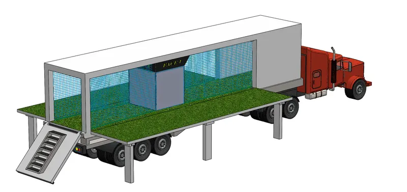
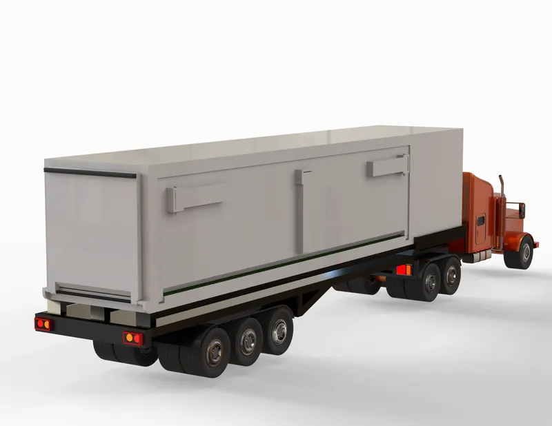
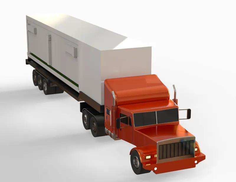
The objective of this SolidWorks Project titled “Football Cube on Wheels” is to design a Trailer Truck with a cubical machine called F-Cube (related to Football), mounted on its Trailer. The idea has been taken from my past job experience where I came across this interactive smart machine being utilized to evaluate Football Players. With this Project, I would like to put my visualization into SolidWorks and create a concept model utilizing the knowledge that I acquired throughout this unique learning process with the Skill-Lync Team.
Introduction
In this project, I have designed individual parts of “Football Cube on Wheels” Project in SolidWorks by making use of various surface modelling tools combined with solid modelling features and reference geometries to eventually mate all the parts to achieve the fully assembled concept model. Actual dimensions are not used in the design process but the visuals are scaled as per the practical application of the model. The approach of feature-based parametric modelling has been followed throughout.
Design Approach
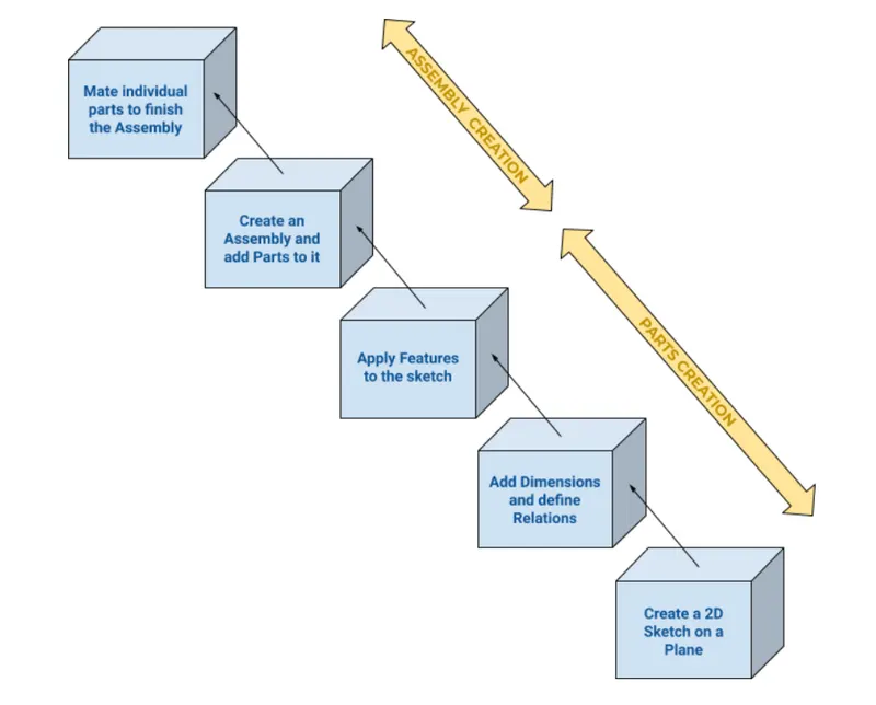
The Parametric feature-based Bottom-up approach has been followed in the modelling of this Project. Please refer to the Flowchart below:
Features & Tools
In making of the “F-Cube on Wheels” model, all the features and tools that were used in SolidWorks are as follows:
- Extruded Boss/Base: This feature extrudes an entire sketch or its selected contours in one or both directions (upto a specified distance which can be altered by the user) to give a desired 3D part. There is also an option to create a Thin Extrude which saves time (bypassing the step of creating two sketches or creating an offset before applying Extrude feature).
- Extruded Cut: This feature extrudes a sketched profile of a solid model to cut it in one or two directions.
- Lofted Surface: Creates a lofted surface between two or more profiles.
- Filled Surface: Constructs a surface patch within a boundary defined by existing model edges, sketches, or curves.
- Plane: A reference plane is added based on the selection of references as per the requirement of our sketch.
- Extruded Surface: Creates an extruded surface from the sketch.
- Thicken: Creates a solid feature by thickening one or more adjacent surfaces which are already knit.
- Shell: A thin-walled feature is created using Shell which removes material from the selected solid body.
- Fillet: We can apply this as a sketch tool while creating our sketch or as a feature after a 2D sketch is transformed into a 3D feature. It rounds the corner of two sketch entities at their intersection point creating a tangent arc. When applied as a 3D feature (solid/surface), it creates a rounded internal or external face along one or more edges.
- Dome: This creates a dome shape to the selected face(s) (planar/non-planar).
- Chamfer: We can apply this as a sketch tool while creating our sketch or as a feature after a 2D sketch is transformed into a 3D feature. It creates a transitional edge at the intersection of two sketch entities when used as a sketch tool. When used as a feature, it creates a bevel feature along an edge or a vertex.
- Knit Surface: Combines two or more adjacent, non-intersecting surfaces together.
- Delete Face: Deletes faces from solid bodies to create surfaces, or deletes faces from surface bodies.
- Surface Plane: Creates a planar surface using a sketch or set of edges.
- Ruled Surface: Inserts ruled surfaces from edges.
- Trim Surface: Trims a surface where one surface intersects with another surface, a plane, or a sketch.
- Linear Pattern: It creates a pattern of features, faces and bodies in one or two linear directions.
- Swept Boss/Base: Sweeps a closed profile along an open or closed path to create a solid feature.
- Mirror: This can be used as a sketch tool or as a feature. In sketch mode, it mirrors the selected entities about a reference plane or centerline. When used as a feature on a 3D body, it mirrors the features, faces and bodies about a face or a plane.
- Circular Pattern: It creates a pattern of features, faces and bodies around an axis.
- Revolved Boss/Base: To create a solid feature, a sketch or its selected contours are revolved around an axis.
- 3D Sketch: Creates a new sketch in 3D space.
- Hole Wizard: Inserts a hole using a predefined cross-section.
- Split: This feature creates multiple bodies from a single body.
Assembly Mates
While assembling the designed parts, I applied the following mates to achieve desired orientation:
Standard Mates:
- Coincident: It is used to position selected planes, edges, and faces of two components. Two vertices are chosen so that they touch and are coincident to each other.
- Parallel: This keeps selected items at a constant distance from each other irrespective of the change in angular direction of the selected items.
- Perpendicular: To place components at a 90 degree angle from each other, Perpendicular mate is used.
- Tangent: A curved surface/face of a component can be made tangent with another component having a curved surface/face.
- Concentric: The circular face of components share the same centerline when Concentric mate is applied.
- Lock: Keeps two components at the same position and orientation.
- Mate alignment: This mate flips the components so that the face, edge, or plane is aligned correctly with its mating component.
Advanced Mates:
- Angle: It adds a limiting angle between component faces, edges, or planes by specifying a minimum and maximum angle. In the Assembly, angular movement is mostly used to showcase the concept of the Project.
Description
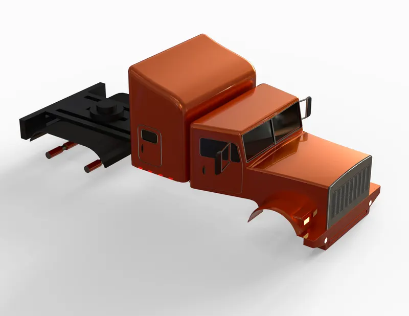
Truck Body
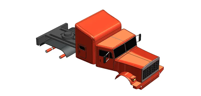
Truck body adds to the aesthetic detail of this designed model. The focus areas in the Truck Body are:
- Hood
- Radiator Grille
- Front Bumper
- Fenders
- Headlights
- Windshield
- Doors
I have included the chassis frame as well with the Truck Body. The design used to make the chassis frame is truly hypothetical and is a result of my imagination put into a 3D model.
Tools/Features used:
- Extruded Boss/Base
- Extruded Cut
- Lofted Surface
- Filled Surface
- Plane
- Extruded Surface
- Thicken
- Shell
- Fillet
- Dome
- Chamfer
- Knit Surface
- Delete Face
- Surface Plane
- Ruled Surface
- Trim Surface
- Linear Pattern
- Swept Boss/Base
- Mirror
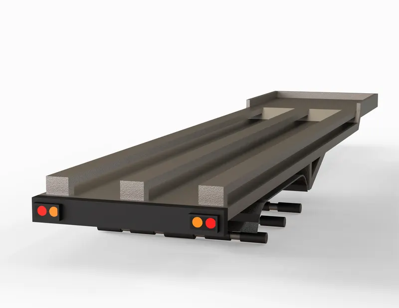
Trailer Bed
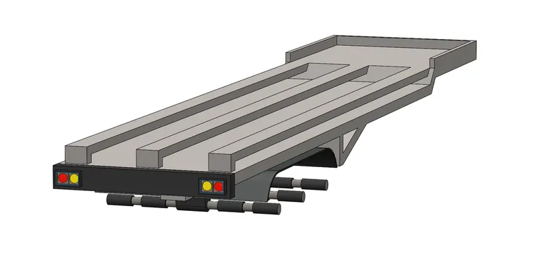
The Trailer of a Truck is an unpowered part which is attached with the powered part i.e. the Truck. However the main purpose of a Trailer is to transport goods and material but these days, Trailer Trucks are being used as recreational vehicles with mobile homes where people can camp or stay. In our project, the Trailer is being used to carry F-Cube Machine along with a playing platform about which we will discuss in detail later.
Tools/Features used:
- Extruded Boss/Base
- Plane
- Fillet
- Mirror
- Extruded Cut
- Dome
- Surface Plane
Cargo Container
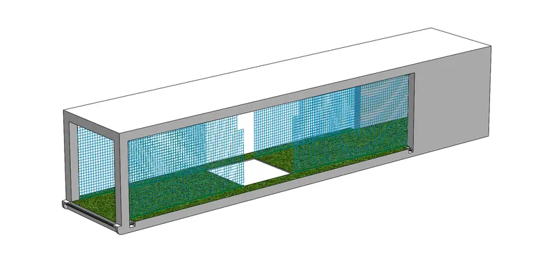
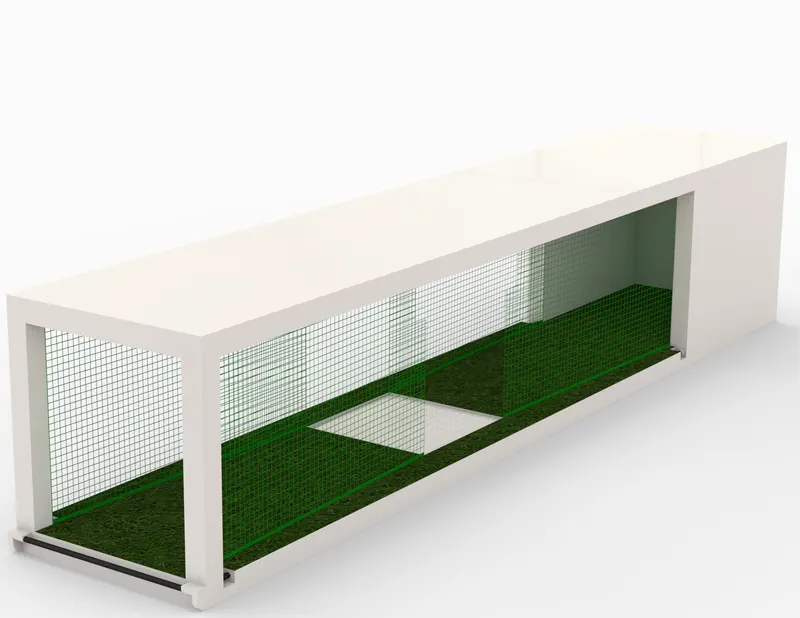
The Cargo Container, also referred to as Container is an enclosed hollow cuboidal body with movable doors (one or multiple) used to carry the heavy shipments or loads. The Cargo Container is mounted on the Trailer about which we discussed in the previous section.
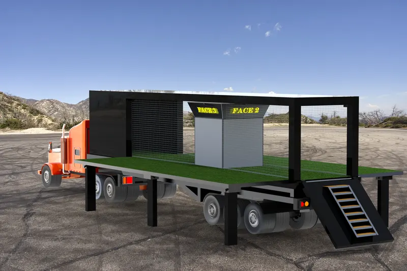
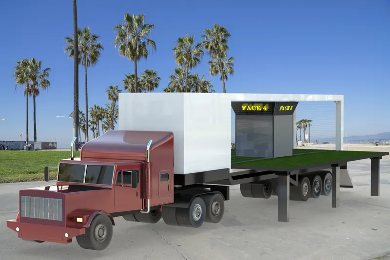
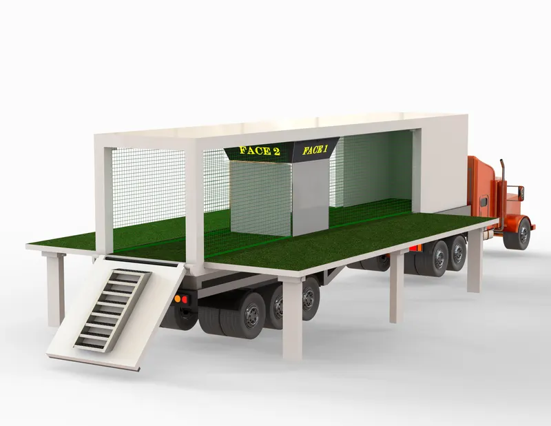
The Cargo Container of this model is designed to depict a small Football Playing Area with its base as an Artificial Turf panel. The F-Cube Machine is mounted in the center of the Container.
Tools/Features used:
- Extruded Boss/Base
- Extruded Cut
- Plane
- Mirror
- Lofted Surface
- Trim Surface
Football Cube Machine (F-Cube)
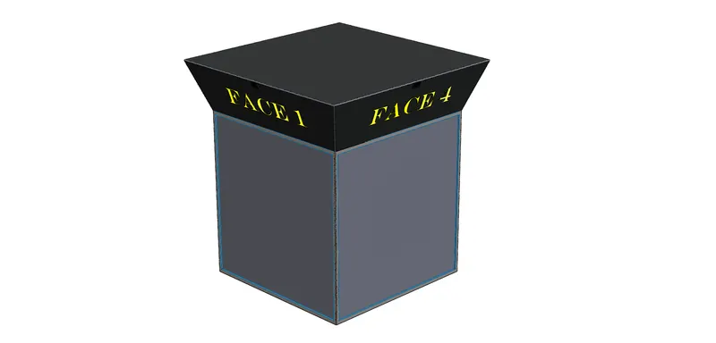
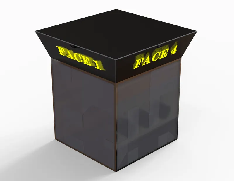
F-Cube Machine is the prime focus of creating this conceptual model which is mounted on the base of the Cargo Container. It is a sensor based interactive and intelligent device created for Football & Fitness Training, Assessment and Practice. It quantifies football attributes of the players and creates their digital evaluation reports and also helps in the video analysis process. The F-Cube has four active Faces and a Speed Sensing camera is fixed at the top edge of each Face. Each Face is made of thick Polycarbonate sheet to resist the repetitive impact of football shots. The display which appears on the screen is made possible with the help of heavy duty screen projectors which are mounted inside this cubical structure at the top surface.
Tools/Features used:
- Extruded Boss/Base
- Extruded Cut
- Plane
- Shell
- Extruded Surface
- Swept Boss/Base
- Fillet
- Dome
- Circular Pattern
Wheel
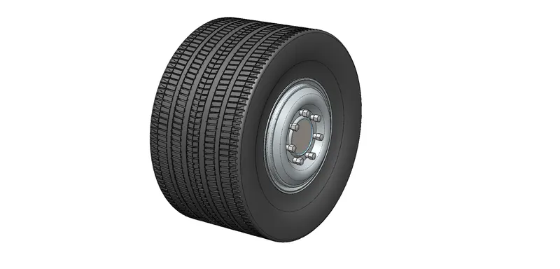
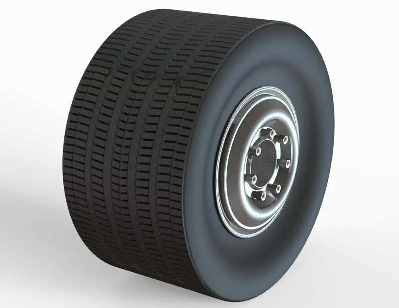
There are a total of 22 wheels in our model. The wheel is designed with Tire and Rim together as a single part. The tread pattern on the Tire is made by applying a circular pattern to a couple of extruded cut designs to get a realistic look.
Tools/Features used:
- Revolved Boss/Base
- Fillet
- Extruded Cut
- Extruded Boss/Base
- Plane
- Circular Pattern
- Dome
- Delete Face
- Surface Plane
- Knit Surface
Side Exhaust
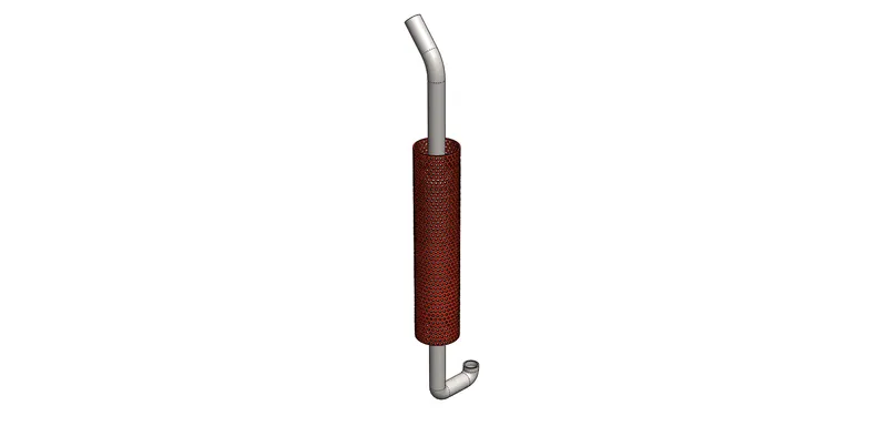
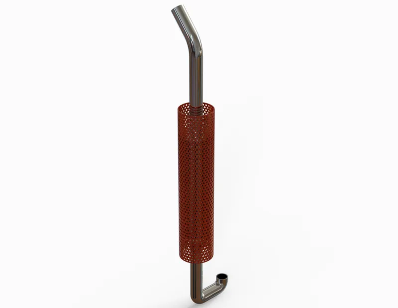
There are two Side Exhausts in the model which are attached on either side of the Truck. Exhaust System of a vehicle guides the burnt gases from the engine to escape into the environment via a piping structure after passing through an exhaust catalytic converter which reduces the toxicity of pollutant gases.
Tools/Features used:
- Revolved Boss/Base
- Swept Boss/Base
- Hole Wizard
- Circular Pattern
- Extruded Boss/Base
- Extruded Cut
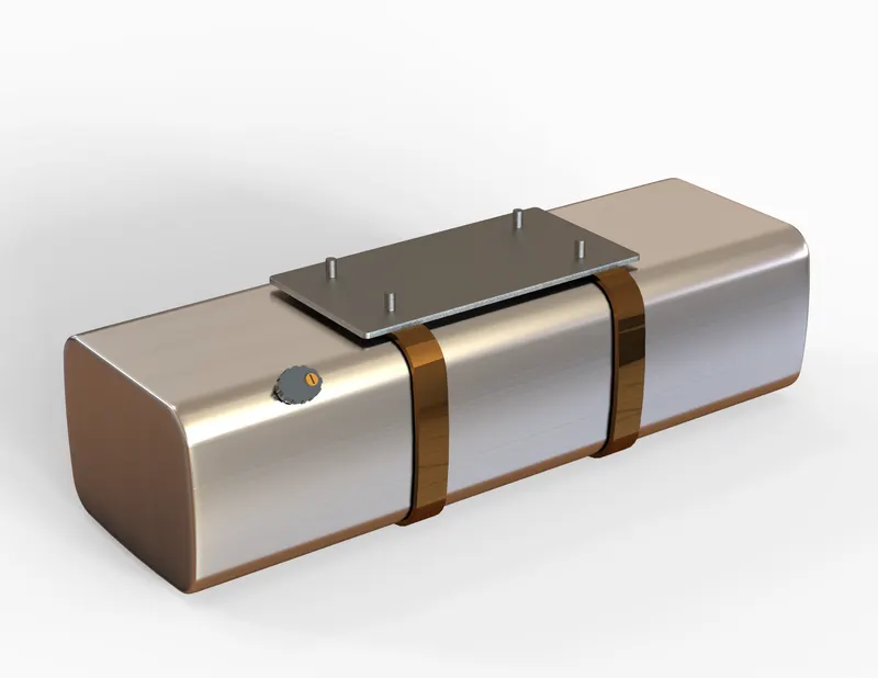
Fuel Tank
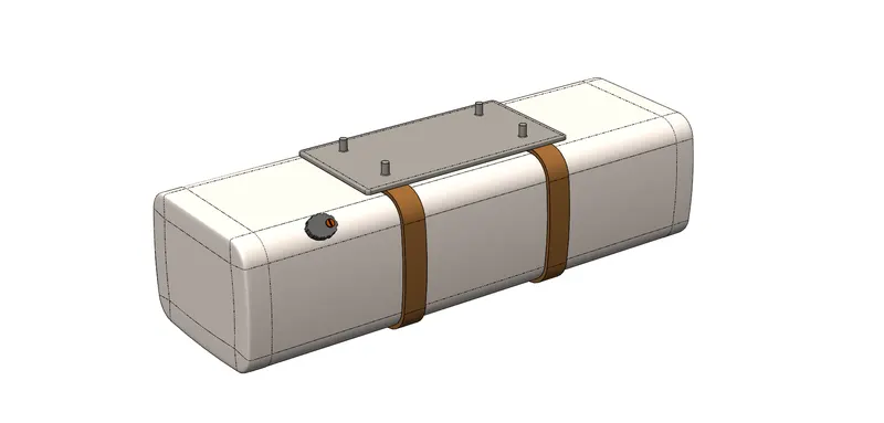
A generic design of Fuel Tank has been taken which is attached beneath the Truck Body. Again, the focus is only on the visuals and not on the connectivity of the fuel pipes to the engine.
Tools/Features used:
- Extruded Boss/Base
- Plane
- Fillet
- Split
- Extruded Cut
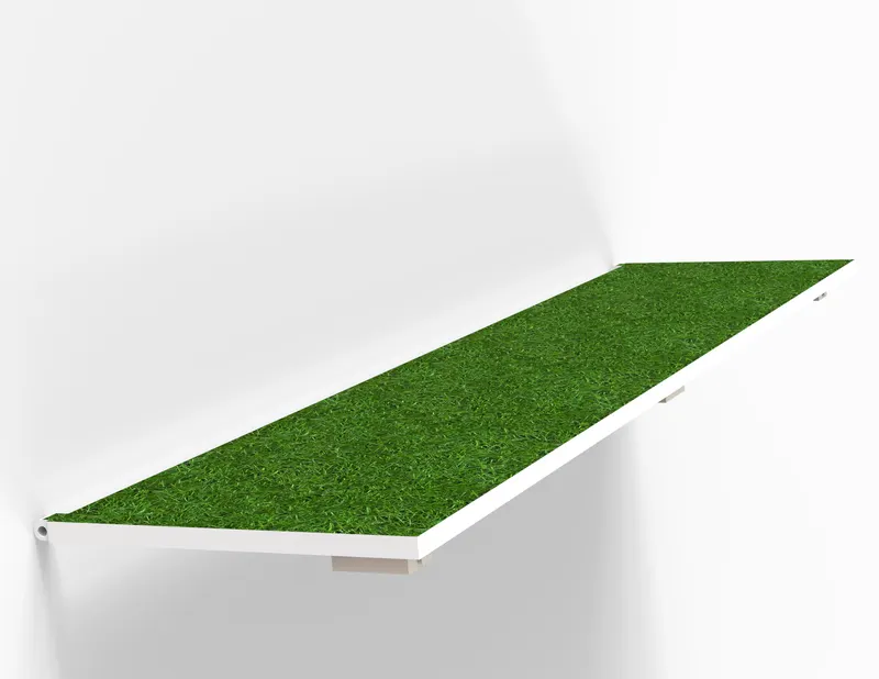
Side Folding Door
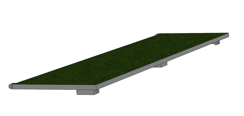
This side door is made retractable so that it can be drawn and withdrawn as required to use F-Cube. The inner side of the doors is fixed with an Artificial Turf Panel, same as used in the base of the Cargo Container. There are two Side Folding Doors in our model.
Tools/Features used:
- Extruded Boss/Base
- Extruded Cut
- Chamfer
- Fillet
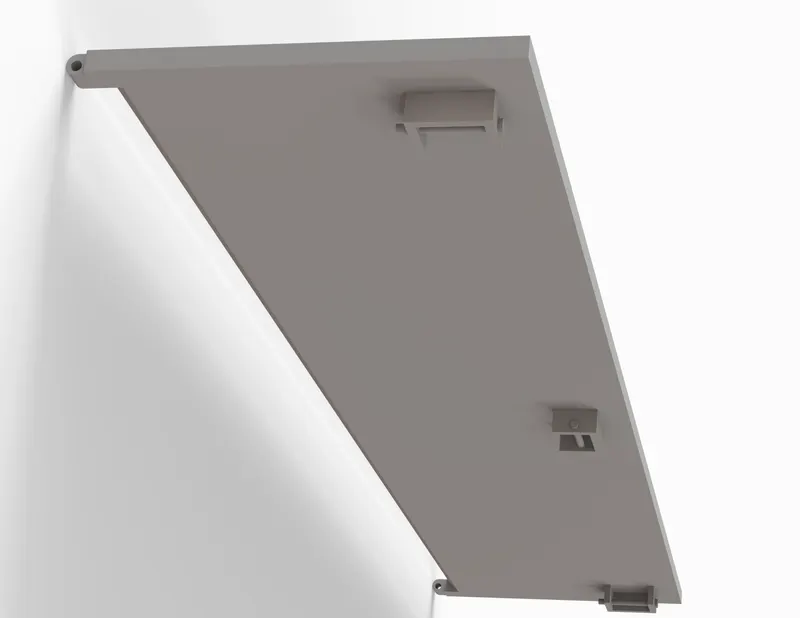
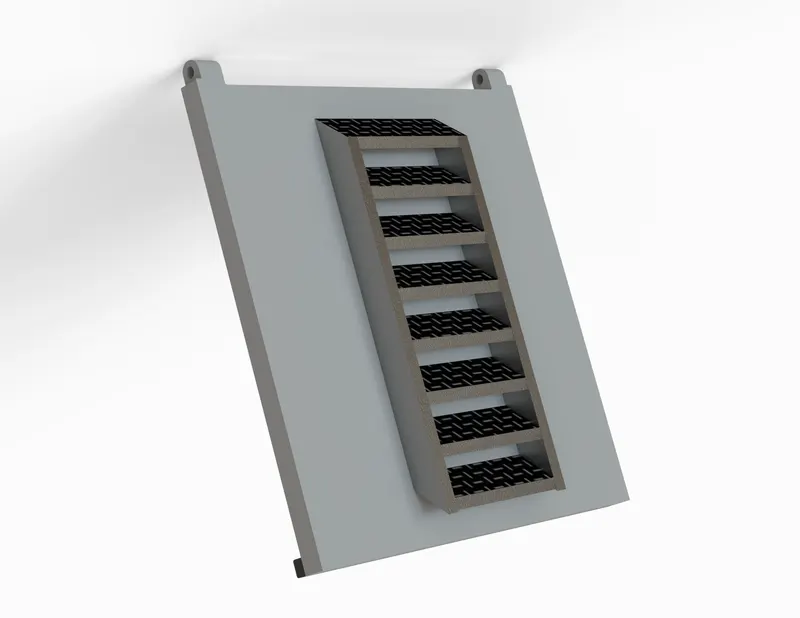
Rear Folding Door & Ramp
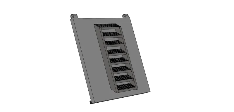
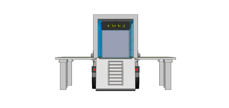
As depicted in the visual above, this is a rear opening of the Cargo Container which also serves as a ramp with a ladder attached to it. The ladder is mounted on the inner side of the door. This Rear Door is also retractable which can be drawn and withdrawn as per requirement.
Tools/Features used:
- Extruded Boss/Base
- Extruded Cut
- Chamfer
- Fillet
- Plane
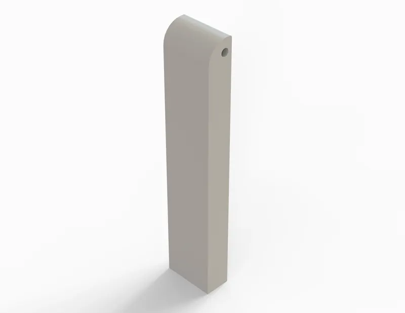
Folding Pillar
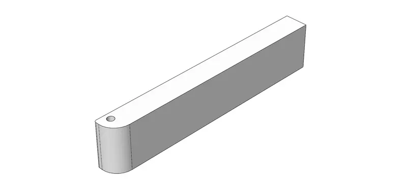
Three Folding Pillars are designed and attached to Side Folding Doors to withstand their load when the doors are retracted or drawn out. These solid pillar structures will act as a base support for the Playing Platform (Side Folding Doors).
Tools/Features used:
- Extruded Boss/Base
- Extruded Cut
- Fillet
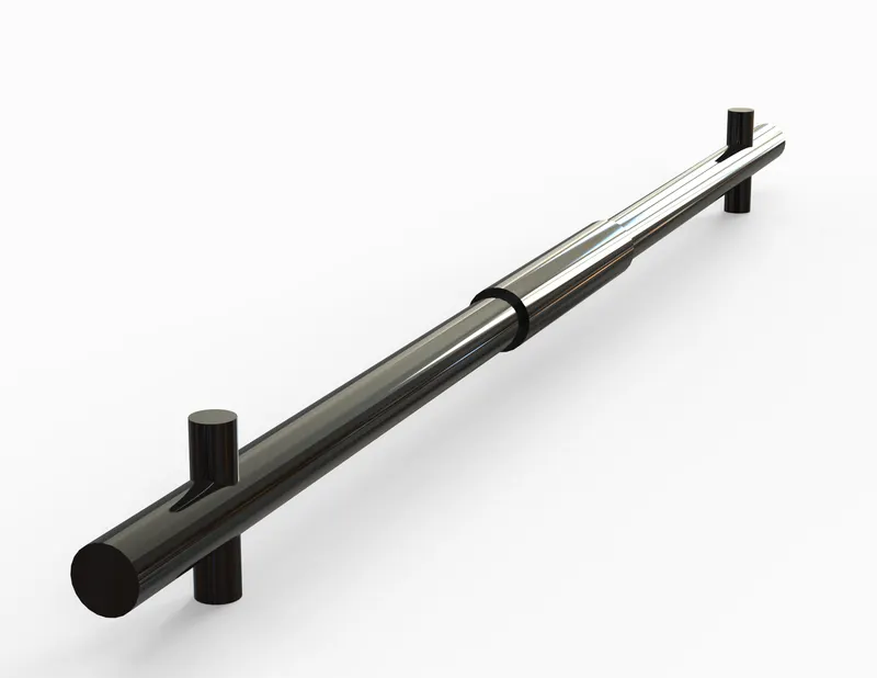
Front Axle Rod
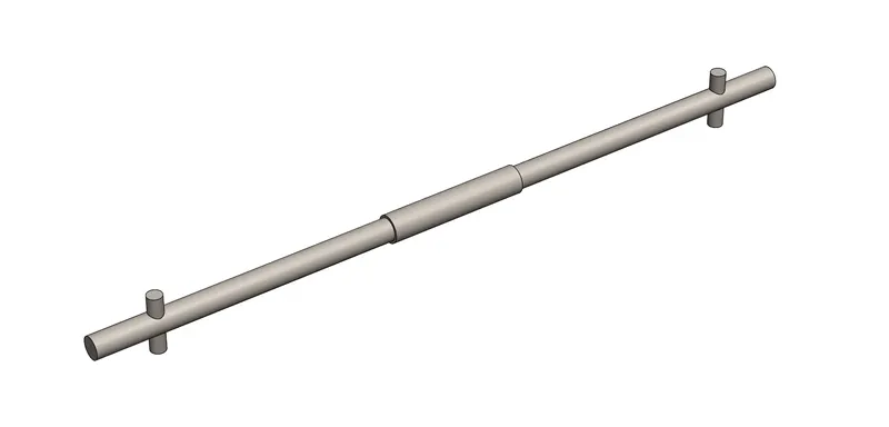
In Automotive Industry, the front axle is used to connect the wheels of a vehicle to transmit driving torque to the wheel, as well as to maintain the position of the wheels relative to each other and to the vehicle body. I haven’t gone into the detail of this complex component and have just made a simple rod structure that connects the front wheels of our Truck and allow them to rotate and turn sideways.
Tools/Features used:
- Extruded Boss/Base
Assembly Model View Images
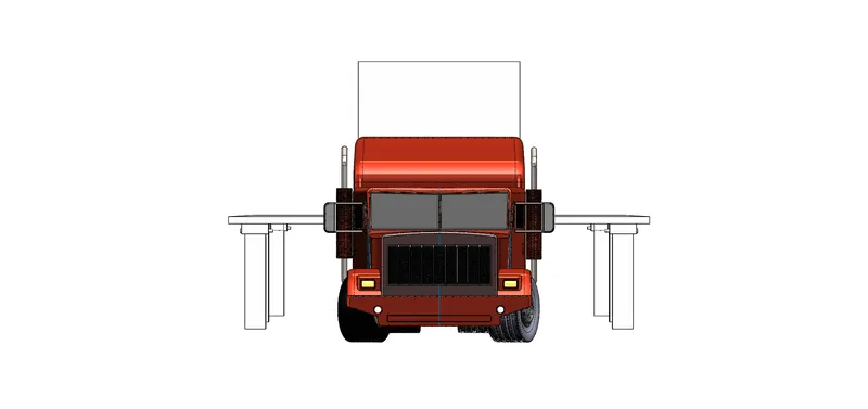
Front View
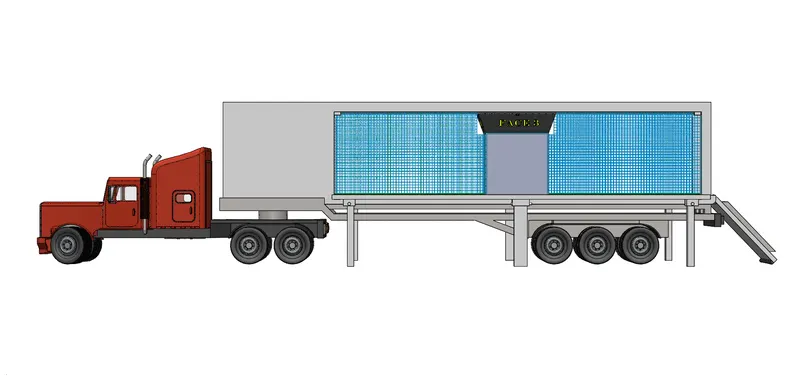
Left Side View
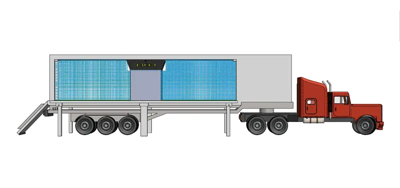
Right Side View
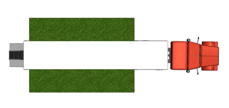
Top View
Back View
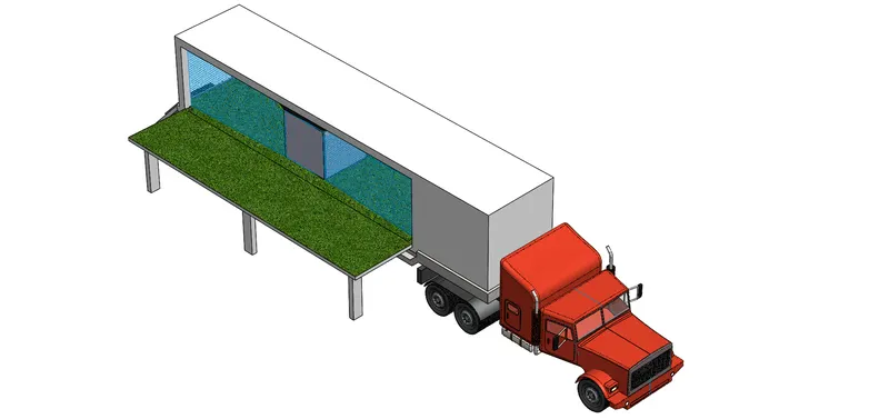
Isometric View
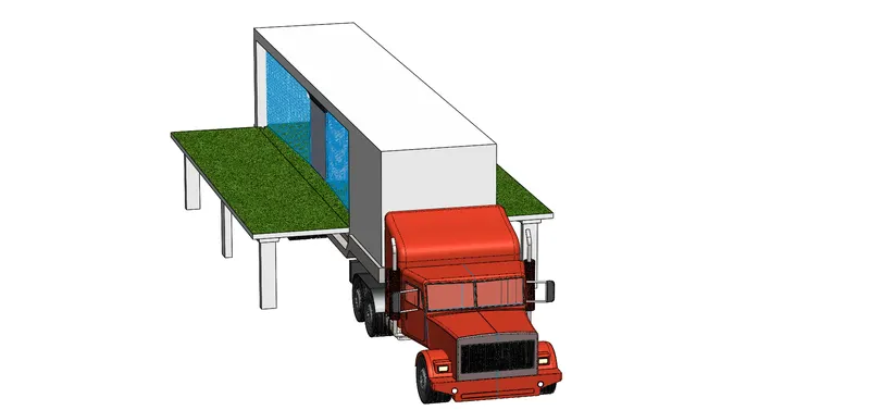
Custom View
Camera Setup
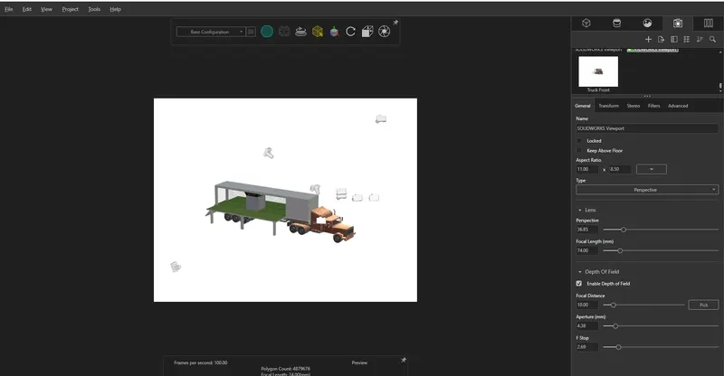
Rendered Images - Assembly Model & Individual Parts
Final Render - Football Cube on Wheels
Truck Body
Trailer Bed
Cargo Container
Football Cube Machine (F-Cube)
Wheel
Side Exhaust
Fuel Tank
Side Folding Door
Rear Folding Door & Ramp
Folding Pillar
Front Axle Rod
Conclusion
This challenge of creating an Independent Project in SolidWorks enabled me to apply the knowledge that I acquired across the Ultimate SolidWorks Course powered by Skill-Lync Team and the practical training of the entire exercise made it possible to create a conceptual model of F-Cube Technology mounted on a vehicle. I utilized all the basic concepts of part, surface and assembly modelling to design this Project. As stated above as well, the prime objective was not to visualize the model with a perspective of an automotive system, hence there is no replication of actual vehicle parts such as Chassis Frame, Engine, Steering System and Exhaust System. SolidWorks Visualize was used to generate the final renders. Some tweaks were made with the object orientation, HDR environment, backplate adjustments, brightness & gamma level, shadows, reflections, scale, addition of realistic appearances to different parts which resulted in crisp and realistic images for the final renders. Finally, I created this SolidWorks Project to showcase my conceptual model.
References
The image files which were referred to get an idea on proceeding with this Project are attached with the Part and Assembly files: