Numerical Analysis and Emission characterization on a CAT3410 engine
In this challenge, two different piston bowl configurations of CAT3410 Engine are analyzed and their emissions are characterized.
Objectives:
- To make the engine sector surface by providing the bowl profile. (sector is made to be computationally efficient, rather than simulating the entire domain).
- To set up the case for spray, combustion, and emissions.
- To post-process the results and perform a comparative study for the selected bowl configurations.
Geometry:
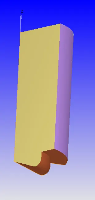
The geometry of the piston-cylinder of the engine is as shown below.
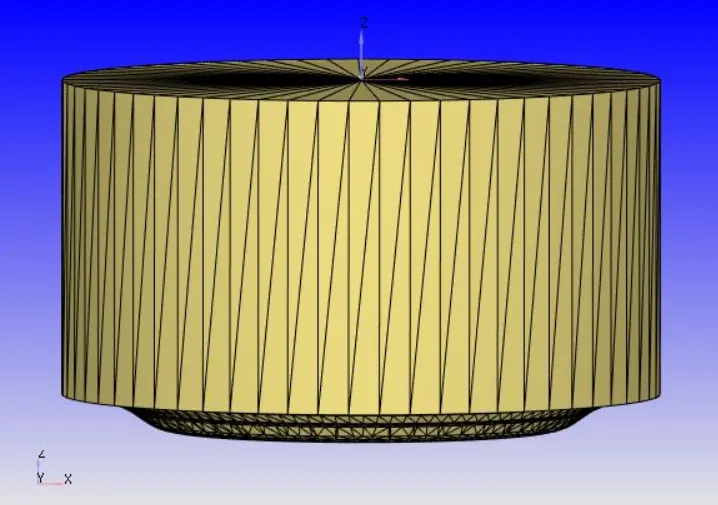
As the above setup does not consist of any exhaust and inlet valves. This problem is solved as a closed cycle system. Moreover, to be computationally efficient only a sector of the above geometry is solved.
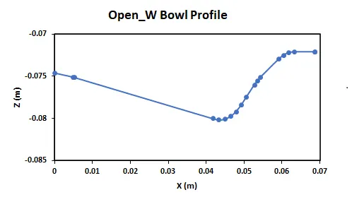
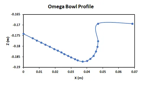
Furthermore, to extract the sectors of the engines we used the "Make engine sector surface" option wherein the bowl profiles are loaded and the sectors are obtained.
Bowl Profile for Open-W piston:
Bowl Profile for Omega piston:
Prior to providing the bowl profile of piston the geometric parameters of the engine and sector are set.
| Parameter | Dimensions |
| Bore | 0.13716 m |
| Stroke | 0.1651 m |
| Connecting Rod | 0.263 m |
| RPM | 1600 |
| Sector Angle | 60 |
| Compression Ratio | 17.5 |
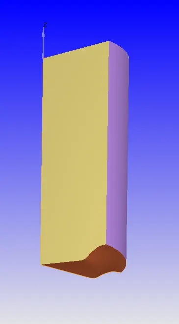
Once all the given parameters are set and bowl profiles are imported. The sector of the engine geometry is ready in the Converge Studio.
 |
 |
| Open - W | Omega |
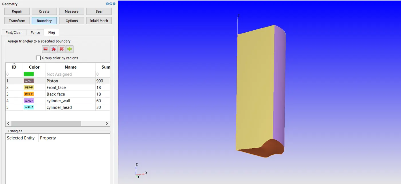
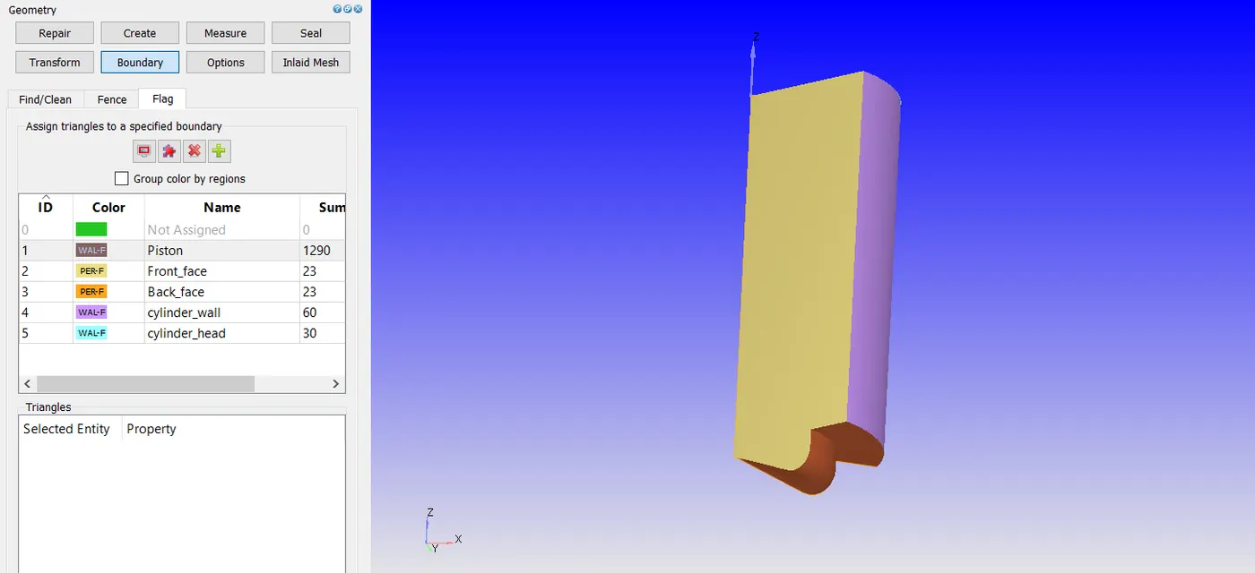
Before moving up with further modeling, boundaries and regions are assigned and flagged as to below.
Boundary Flagging for Open-W Piston:
Boundary Flagging for Omega Piston:
Simulation Parameters:
| Case Parameters | Setup |
| Application Type | Crank angle-based IC engine |
| Physical Parameters |
Cylinder Bore: 0.13716m Stroke: 0.1651m Connecting rod length: 0.263m Crank speed: 1600rpm |
| Gas Simulation | Therm.dat uploaded |
| Parcel Simulation | DIESEL 2 (Predefined Liquid) |
| Reaction Mechanism | Mech.dat uploaded |
| Run Parameters |
Solver - Transient Type - Crank angle-based engine simulation Simulation mode - Full Hydrodynamic |
| Simulation Time Parameters |
Start time: -147 deg End time: 135 deg Initial Time Step: 5e-7s |
| Solver Parameters |
Solver Scheme: PISO Type: Density-based |
Boundary Conditions:
| Piston |
Boundary Type - Wall Wall motion - Translating Surface Movement - Moving Law of Wall (Piston Motion) Temperature - 533K (Law of Wall) |
| Front Face |
Boundary Type - Periodic Periodic Type - Stationary Periodic Shape - Rotational Angle - 60 [deg] |
| Back Face |
Boundary Type - Periodic Periodic Type - Matched Boundary Matching Boundary - Front Face |
| Cylinder Head | Boundary Type - Wall
Wall motion - Stationary Surface Movement - Fixed Law of Wall Temperature - 523K (Law of Wall) |
| Cylinder Wall | Boundary Type - Wall
Wall motion - Stationary Surface Movement - Fixed Law of Wall Temperature - 433K (Law of Wall) |
Regions and Initialization:
All the boundaries are assigned to the single region
| Parameter | Value | ||||||||||
| Temperature | 355 K | ||||||||||
| Pressure | 197000 Pa | ||||||||||
| Species |
|
Physical Models:
Spray Modeling:
Converge uses state of art models for spray processes involving liquid atomization, drop breakup, collision & coalescence, turbulent dispersion & drop evaporation in terms of liquid sprays. Converge uses a Lagrangian solver to model discrete particles and Eulerian solver to model the continuous fluid domain. Lagrangian specification of the flow field is a way of looking at fluid motion where the observer follows an individual fluid parcel as it moves through space and time. Plotting the position of an individual parcel through time gives the pathline of the parcel. The Eulerian specification of the flow field is a way of looking at the fluid motion that focusses on specific locations in the space through which the fluid flows as time passes. The eulerian cell center is fixed while the lagrangian parcels move. Heat, momentum & mass transfer occur between the discrete and continuous phases via source terms in transport equations.
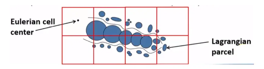
Parcels are introduced into the domain at the injector, which presents a group of identical drops with the same radius, velocity, and temperature. The parcel is the basic unit converge solves instead of drop. Parcel undergoes several physical processes like a primary breakup, secondary breakup, drop, drag, collision & coalescence, and evaporation.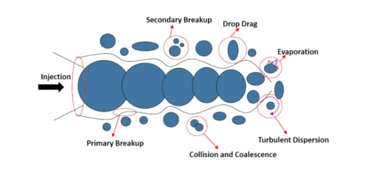
Evaporation Model:
The spray evaporation that takes place needs to be considered and for that converge uses certain standard pre-created models such as Frossling, Chiang, or with boiling. In this project, the Frossling model is used and it does not need to provide the particular equations as Converge takes care of it. Converge asks for evaporation source to simulate multi-component vaporization. The source used in this project is "Source all base parcel species" which denotes multi-component liquid species evaporate into the base species.
As the evaporation source is specified, the maximum radius of ODE droplet heating needs to be specified as well, its basically a temperature discretization parameter which will control if drop temperature is uniform or radially varying. If the drop radius exceeds maximum value the converge assumes a radially varying temperature or else uniform temperature distribution is assumed.
Spray Penetration and Distribution:
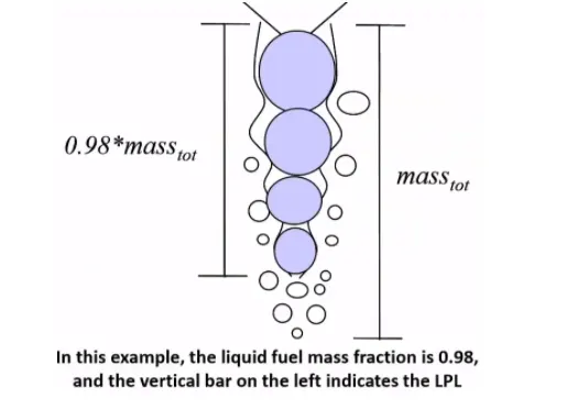
Converge writes the liquid and vapor penetration lengths at each output interval, it calculates vapor penetration length for each nozzle. For each cell that meets the criteria that fuel vapor mass fraction exceeds the user-specified value or cell size does not exceed user-specified bin size, converge calculates the center of the nozzle to the center of the cell.
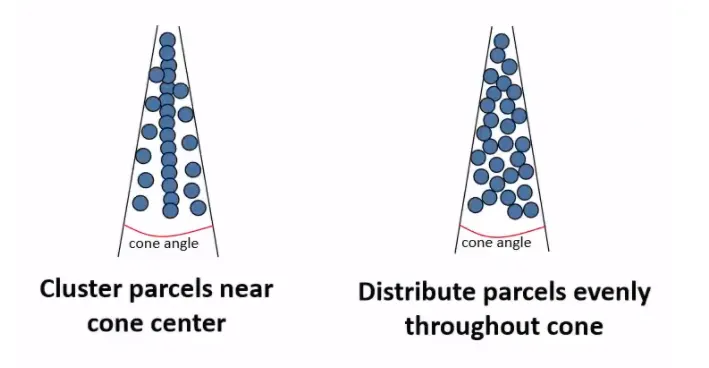
The parcel distribution is done in two ways where the parcels are either distributed evenly throughout the cone or clustered near the center of the cone. Depending upon the requirement either distribution can be selected, for this project, Cluster parcels near the cone center are selected.
Collision/Coalescence & Drop Drag:
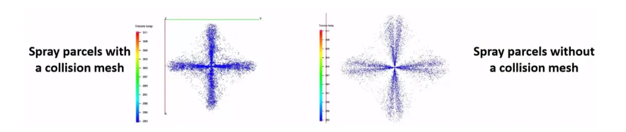
If in a spray simulation parcels collide with parcels only in the same cell, it can lead to grid sensitivity, which is why converge has an adaptive collision mesh to reduce the grid sensitivity, Once collision mesh is checked, the parcels can collide across grid cells, requiring no additional mesh or any other setup. In this project, it is done using a standard NTC collision model & dynamic drop drag calculates the drag coefficient to account for variation in drop shape as shown in spray breakup. In the figure shown below, it is observed that parcels with collision mesh look more reasonable & natural, Othe drop options are spherical drop drag & No drop drag.
Injector & Nozzle
Once the spray breakup & parcel modeling is done, injectors and nozzles need to be specified in their locations, models, radius, etc, In this project, there is 1 nozzle for 60 [deg] sector (on total 6). This is done as per the engine manufacturer's requirement based on the amount of fuel and speed at which the fuel has to be sprayed inside the chamber. The injector has a rate profile where its rate vs crank is determined (normalized for injection duration) is as shown below.
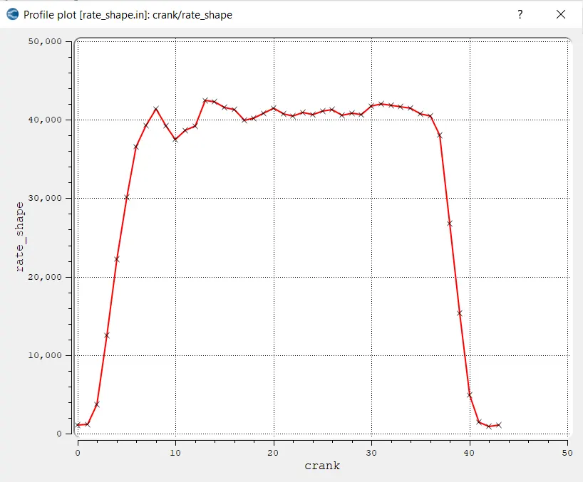
The fuel is specified for this injector as DIESEL2 with mass fraction 1 as fuel is sprayed through the injector. Kelvin-Helmholtz & rayleigh Taylor models are used. The discharge coefficient recommendation for DIESEL - correlation for Cv - 0.7 is set.
Nozzles are added at the injector where nozzle parameters are mentioned such as diameter, injection mass & duration, radius, and spray cone angle as well as co-ordinates of the nozzle.
| Parameters | Input | ||||||||||||||
| General | |||||||||||||||
| Parcel Distribution | Cluster Parcels near the cone center | ||||||||||||||
| Turbulent Dispersion | O'Rourke model | ||||||||||||||
| Drop Evaporation | Use evaporation model | ||||||||||||||
| Frossling Model | 0 - Source specified species | ||||||||||||||
| Collision/Breakup/Drag | |||||||||||||||
| Model |
|
||||||||||||||
| Injectors | |||||||||||||||
| Nozzles |
|
Nozzle Location:
| Nozzle Diameter | 0.000259 m |
| Injection radius | 0.0001295 m |
| Nozzle radial position | 0.00097 m |
| Tilt angle in the XZ plane | 62.55 [deg] |
| Co-ordinates of Injector | (0, 0, -0.0032208) |
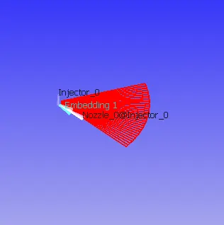
The figure below shows the location of nozzle in the engine.
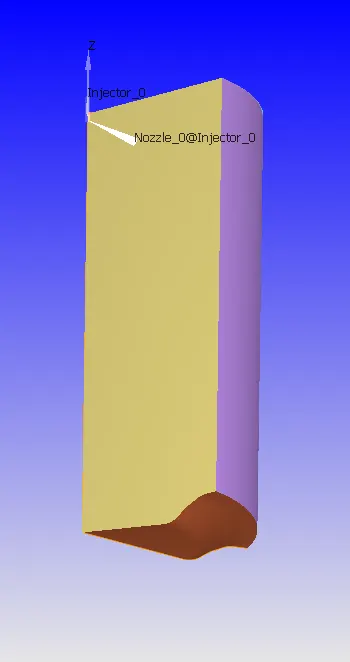 |
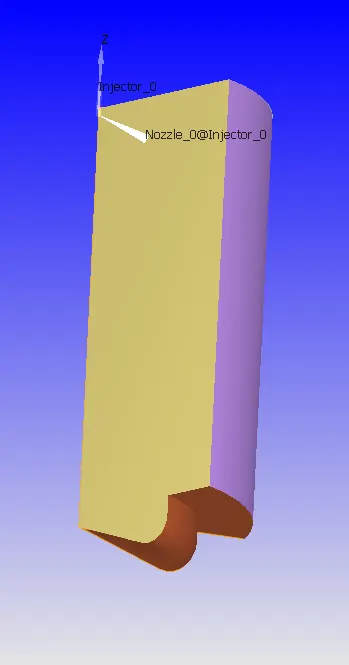 |
| Open-W | Omega |
Combustion Modelling:
Combustion facilitates the energy transfer in the engine. Converge contains detailed chemistry solver and simplified combustion models. In the present project, we will be using SAGE detailed chemical kinetics solver.
SAGE:
The SAGE detailed chemistry solver is a general combustion model used to solve the detailed chemical kinetics in the combustion process. It can accurately model ignition and laminar flame propagation. It uses local conditions to calculate reaction rates based on the principles of chemical kinetics. Also, determines kinetically limited phenomenon of engine knock and emissions. It requires a CHEMKIN-formatted input fils to solve the reaction rate ODEs. The ODE solver used is called as CVODE solver. SAGE couples with transport solver via source terms in the species transport equations.
A chemical reaction mechanism is a set of elementary reactions that describe an overall chemical reaction. The combustion of different fuels can be modeled. SAGE calculates the reaction rates for each elementary reaction while the CFD solver solves the transport equations. Given an accurate mechanism, SAGE (in addition to AMR) can be used for modeling many combustion regimes (ignitions, premixed, mixing-controlled). You can use SAGE to model either constant volume or constant pressure combustion.
In each time step, the chemistry solver calculates the new species mass fractions immediately prior to solving transport equations. The change in species mass fractions is treated as a source.
`(∂barρtildeY_m)/(∂t)+(∂barρtildeu_jtildeY_m)/(∂x_j)=∂/(∂x_j)(barρD_t(∂tildeY_m)/(∂x_j))+color(red)(tildedotω_m)`
The red color term is the source term. Detailed mathematical modeling can be found in Converge 3.0 manual.
As this is the most detailed solver, solving it in every cell can be expensive, time-consuming. Converge has accelerating options that require increasing minimum cell temperature and min HC species mole fraction to reduce the number of cells in which combustion calculations are performed. Using start time and end time to limit SAGE to a specific time interval and can limit SAGE operation to a specific region. Other options include setting resolve only if temperature changes by a specified value. Using analytical jacobian to pass an analytically calculated jacobian to the solver. SAGE also reduces time by using multizone modeling where it groups cells into bins for which options are provided in Converge.
| Parameter | Input | ||||||||||
| Model | SAGE detailed Chemistry Solver | ||||||||||
| General | C7H16 fuel | ||||||||||
| Activation Timing |
|
||||||||||
| SAGE Parameters |
|
||||||||||
| Adaptive Zoning |
|
||||||||||
| Emission Modeling |
Thermal NOX (Extended Zeldovich) Use Hiroyasu-NSC soot model |
Grid Control:
A base grid of 4e-3m is used with AMR and fixed embedding options.
Adaptive Mesh Refinement:
Adaptive mesh refinement is a method of adapting and enhancing the grid dynamically depending upon the variation in the second-order variation of parameters.
Velocity SGS
It is permanent with an embedding level of 2 for SGS of 2 m/s.
Temperature SGS
It is sequential with an embedding level of 2 for SGS of 5K after the fuel is injected into the cylinder.
The formula used is as below:
`"Grid Size"="Base Grid"/(2^"embedding layers")`
Fixed Embedding Layers:
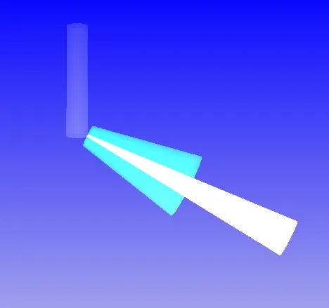
Nozzle Embedding
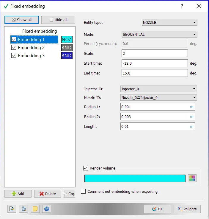 |
 |
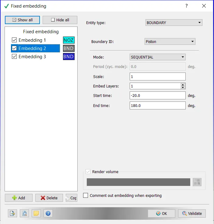
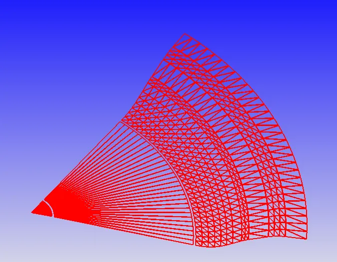
Piston Embedding:
 |
 |
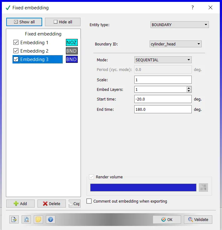
Cylinder Head Embedding:
 |
 |
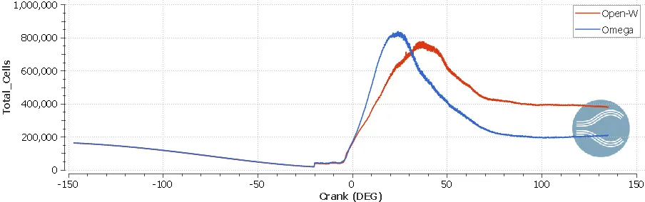
Total Cells:
It shows how the cells are adapted according to the combustion activities and effectiveness of AMR and fixed embedding.
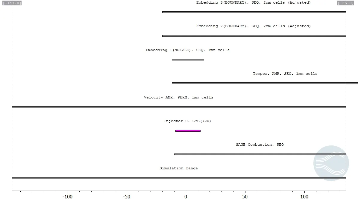
Timing Map:
The timing map is like a pathway that lays out all simulation timing details into something like process charts which displays which process is activated at a particular time. It is a handy tool to verify the activities in one place.
Results and Discussions:
After completing the modeling of the case, the simulation was run using the CYGWIN command line terminal on a 6 core machine. Once it is simulated the data is post-processed using ParaView.
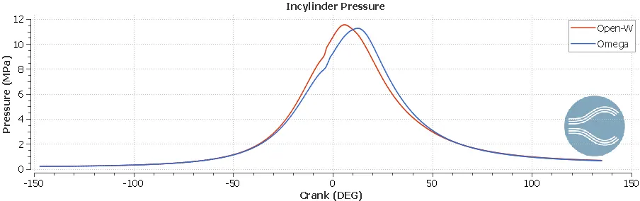
In-Cylinder Pressure:
The cylinder pressure contains different values at different strokes of the cylinder, the highest of which is observed in the combustion/Expansion stroke. This stroke is where the ignition of the air-fuel mixture takes place, creating very high pressure. This is where the engine power is generated. The peak pressure is 11.53 MPa and 11.25 MPa for Open-W and Omega type of piston, respectively.
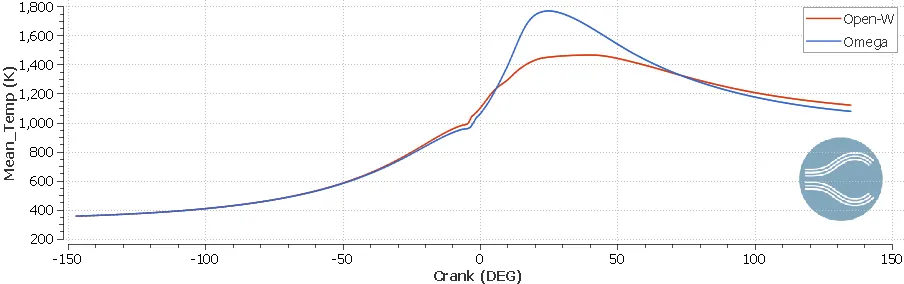
In-Cylinder Mean Temperature:
Maximum temperatures are obtained at the combustion/expansion stroke. The temperature obtained by Omega piston is higher than the Open-w piston.
Volume & Compression Ratio:
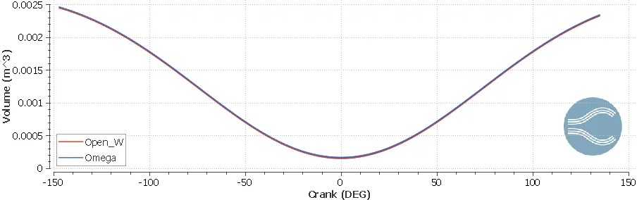
The volume vs crank angle graph plotted in the cylinder region is as shown below.
The compression ratio is defined as below:
Compression Ratio=Maximum VolumeMinimum Volume">Compression Ratio=Maximum VolumeMinimum VolumeCompression Ratio=Maximum VolumeMinimum Volume
| Open-W | Omega | |
| Minimum Volume (m^3) | 0.000148 | 0.000163 |
| Maximum Volume (m^3) | 0.002447 | 0.002463 |
| Compression Ratio | 16.5338 | 15.1105 |
PV Plot:
The diesel internal combustion engine differs from the gasoline powered Otto cycle by using highly compressed hot air to ignite the fuel rather than using a spark plug (compression ignition rather than spark ignition).
`W=∫P.dV`
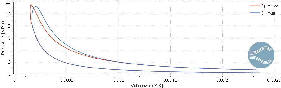
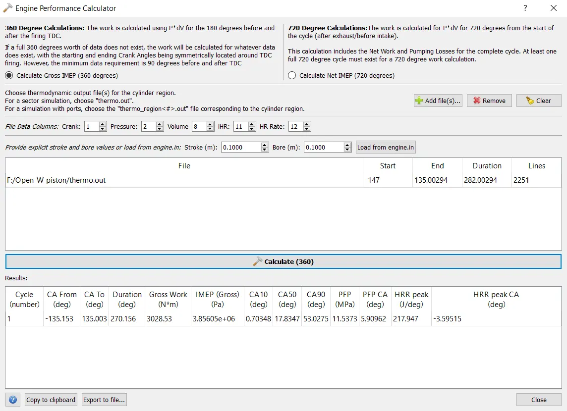
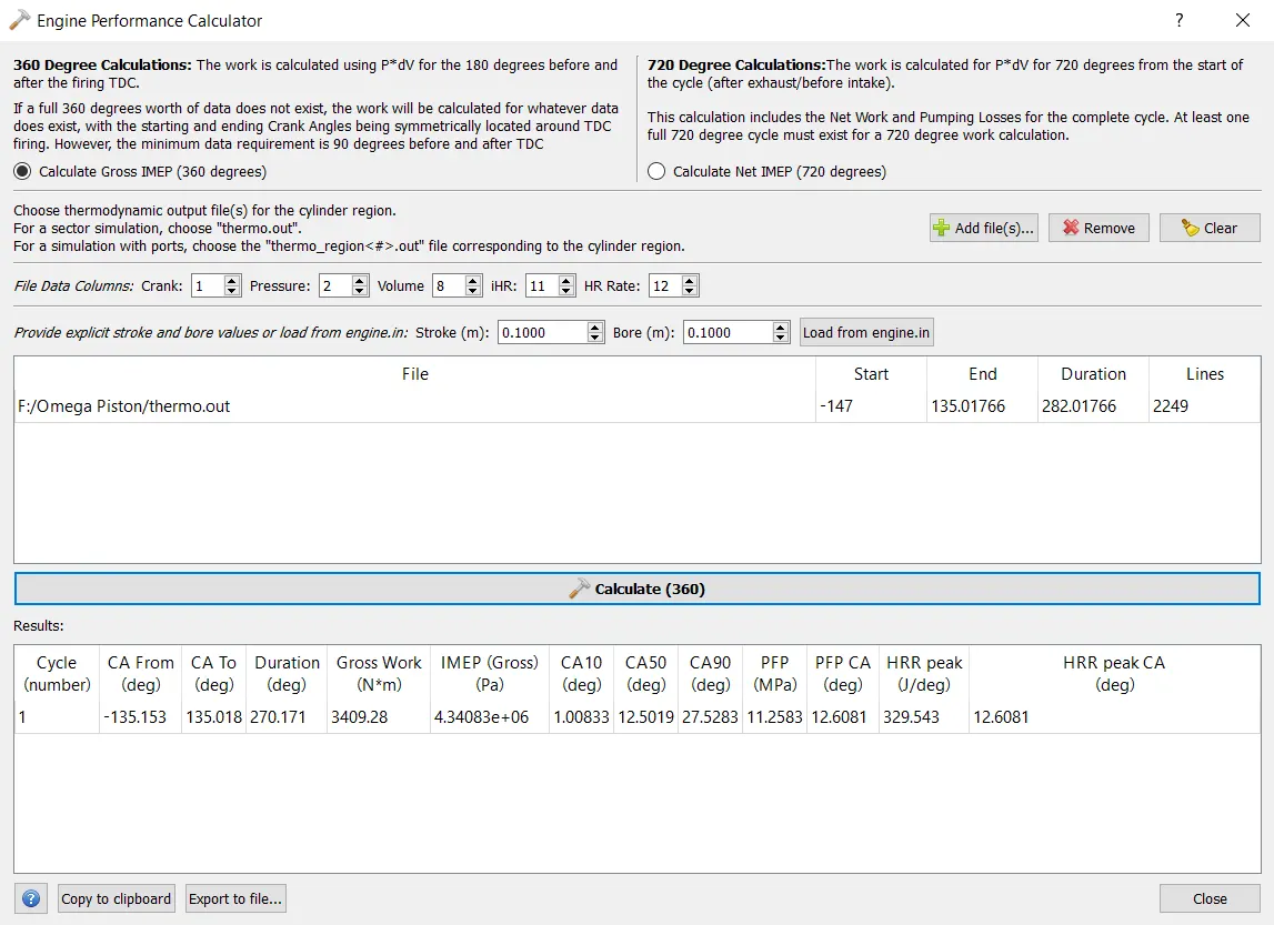
Converge provides an inbuilt engine performance calculator in which all the performance terms can be calculated.
Open-W piston Calculator:
Omega piston Calculator:
| Open-W | Omega | |
| Total Gross Work [Nm] | 3028.53 | 3409.28 |
| Duration of Cycle [deg] | 270.156 | 270.171 |
| RPM | 1600 | 1600 |
| RPS | 26.67 | 26.67 |
| Time for rotation of each degree [s] | 1.04e-4 | 1.04e-4 |
| Time for each cycle [s] | 0.028096 | 0.028098 |
| Number of Cycle in each minute (60/time for each cycle) | 2136 | 2135 |
| Net Power (work/time) [W] | 107792.2124 | 121335.3264 |
| Torque (`(P*60)/(2piN)`) [Nm] | 643.33 | 724.167 |
Heat release rate & combustion efficiency:
Heat release & Integrated heat release is plotted as shown below. It gives the amount of heat i.e., the total amount of heat released from the combustion process. From the total heat release in the combustion chamber, the combustion efficiency of the engine can be determined.
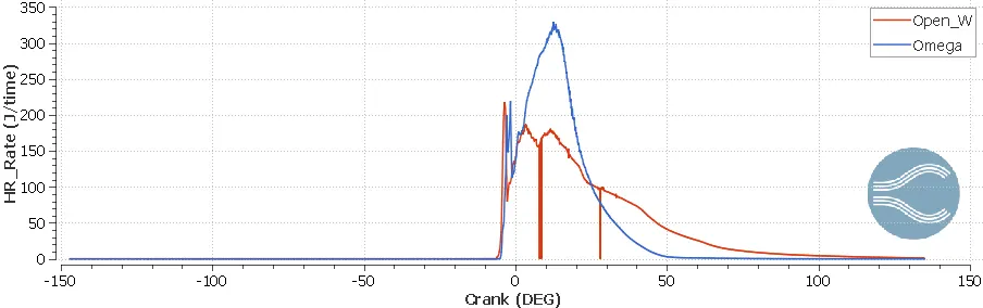
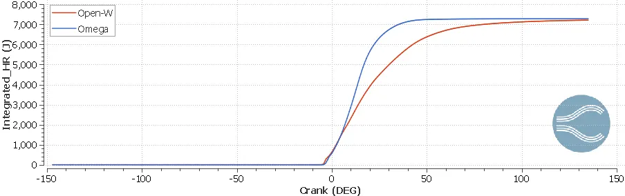
Combustion efficiency is defined as the ratio of total heat energy released by the burning of fuel to the total energy content of fuel mass in a cycle.
Mass of fuel injected = 1.621e-4 kg
Calorific value of fuel = 45.6e6 J/kg
Integrated heat released for Open-W= 7212.06 J
Integrated heat released for Omega = 7279.46 J
`η="Heat Released"/(m.LHV)`
| Open-W | Omega | |
| Combustion Efficiency | 0.97568 | 0.98481 |
Fuel Saving:
From the above, it is clear that the IHR of Omega piston is higher from Open-W piston by 67.4 J.
This means that the excess fuel used by Open-W piston in comparison to Omega piston to generate the same heat.
`67.4/7279.46⋅1.621e^-4=1.5e^-6kg`
Hence, by using Omega piston the amount of fuel saved per cycle is 1.5e-6 kg (fuel wasted by Open-W piston per cycle)
Or per minute the fuel wasted by Open-W piston is
`"Fuel wasted per minute"="fuel wasted per cycle"⋅"Number of cycles in a minute"`
`1.5e^-6*2135=3.2025e^-3`
Hence, by using Omega piston the amount of fuel saved per minute is 3.2025e-3 kg (fuel wasted by Open-W piston per minute)
As can be observed from the calculator figures, CA90 value (the crank angle at which 90% fuel is burnt) is lower for Omega piston in comparison to Open-W piston. Due to faster combustion in Omega piston, efficiency and the power generated are higher than the Open-W piston.
Emission Characterisation:
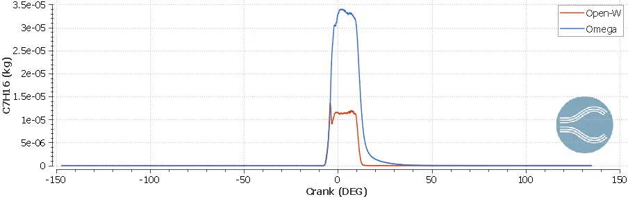
Gaseous Fuel Mass:
For the Omega piston, the larger amount of gaseous fuel is present which is burnt lately. Hence, the temperature increase will be lower for over a duration of the cycle rather than a sudden increase.
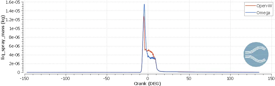
Liquid Spray Mass:
Liquid Spray Parcels:
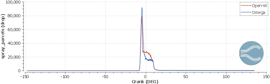
As can be observed from the figure, after the injection of fuel for the Open-W piston the liquid parcels do not evaporate quickly which can be observed in the animation as well. Due to delayed evaporation, the efficiency and Torque produced are less in comparison to Omega Piston.
Penetration Length:
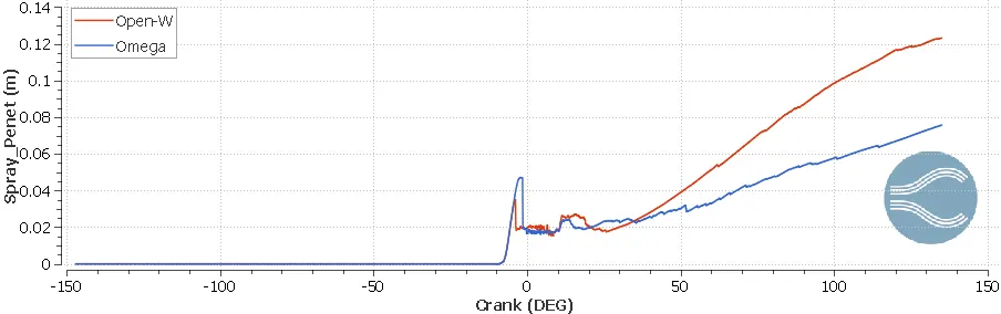
The spray penetration length actually buys time for the fuel to atomize and vaporize in the high pressure and high temperature of the chamber. If there is no time for the liquid to vaporize it sticks on to the bowl profile (fuel impingement) and the fuel is unburnt which is shown in the animation above. Hence, for the Open-W profile injector angle has to be corrected so that the fuel gets enough penetration length to vaporize. As can be seen from the figure below, the penetration for Open-W is less in comparison to Omega Piston (i.e., at the injection of fuel, -10 [deg] CA). Hence, less torque is generated.
Pollutants:
CO Emissions:
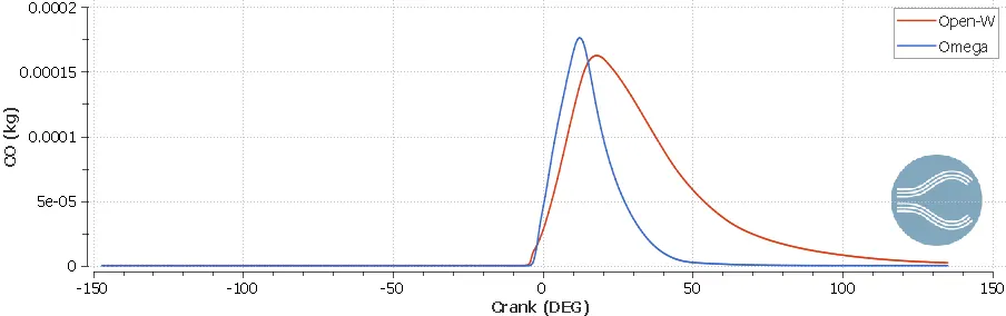
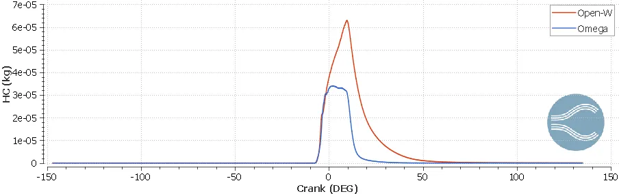
Open-W has higher CO & HC emissions due to the presence of unburnt fuel which is shown in the animation above due to fuel impingement in the Open-W piston.
NOx Emissions:
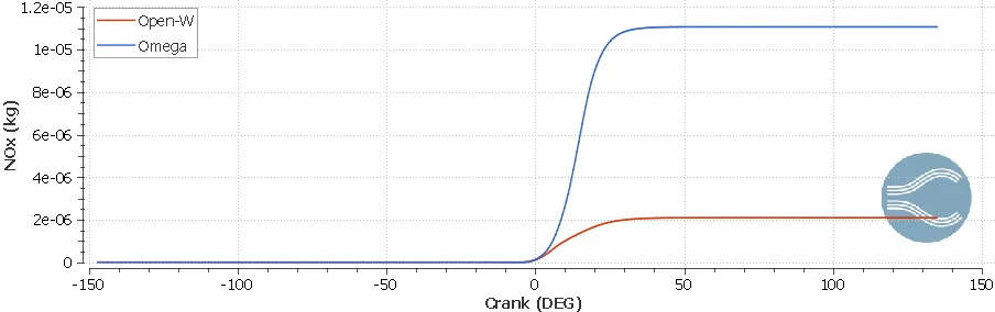
The NOx emissions produced by the Omega piston are higher due to higher temperatures in comparison to the Open-W piston.
Hiroy Soot:
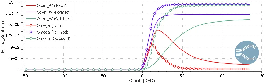
The mass of soot calculated using the Hiroyasu model is shown below. The curves with circle markers belong to the Omega Case. It can be observed that the soot formed by an Omega piston engine is higher in comparison to the Open-W profile it is because the soots get oxidized at a higher temperature.
Conclusions:
- The CAT3410 engine simulation is performed for Open-W and Omega piston profiles.
- Performance and emission characteristics are determined.
- It is evident from the spray wall interaction animation, due to injector angle in the Open-W piston engine fuel impingement takes place which leads to lower Torque and Power generation in comparison to the engine with Omega piston.
- Due to higher temperatures in Omega Pistons, Soot and NOx emissions are higher.
- CO and HC emissions are higher in the Open-W pistons due to unburnt fuel (i.e., due to fuel impingement, fuel sticks to the profile of piston).
- As can be observed from the calculator figures, CA90 value (the crank angle at which 90% fuel is burnt) is lower for Omega piston in comparison to Open-W piston. Due to faster combustion in Omega piston, efficiency and the power generated are higher than the Open-W piston.
- By using Omega piston the amount of fuel saved per minute is 3.2025e-3 kg (fuel wasted by Open-W piston per minute).
- Furthermore, to obtain the higher performance of the Open-W piston injector angle needs to be corrected to avoid the fuel impingement.