FINAL TEST
Port fuel injection(PFI):
1. Compression ratio(`r_c`):
Compression ratio is the ratio of the total cylinder volume when the piston is at the bottom dead centre(`V_t`) to the clearance volume. It is denoted by the letter `r_c`.
`r_c` = `V_t/V_c = (V_c+V_s)/V_c`
`V_c` = clearance volume and `V_s` = Swept or Displacement volume.
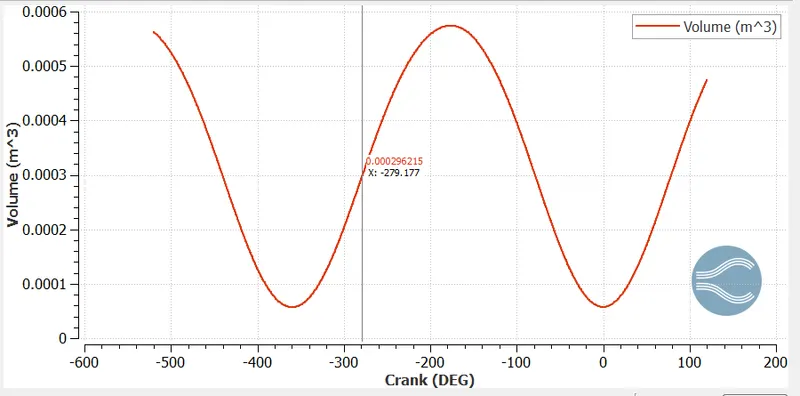
From the above plot the compression ratio is the ratio between the maximum volume and minimum volume of the cylinder. It is denoted by the letter `r_c`.
The maximum value = 5.74218e-4 `m^3` and the minimum value = 5.70426e-5 `m^3`.
`r_c` = maximum volume/minimum volume = 5.74218e-4/5.70426e-5 = 10.066 `m^3`
2. Modify the compression ratio for this engine to 10.3 without changing geometrical parameters. Just need to show the calculation.
From the above calculation, the compression ratio is 10.06 `m^3`. The compression ratio mainly depends upon the displaced volume and clearance volume. The geometrical parameters are displaced volume, bore, stroke, connecting rod, and compression ratio, etc. So, modifying the compression ratio to 10.3 without changing the geometric parameters.
Here we know that compression ratio = 10.3 and minimum(clearance) volume = 5.70426e-5.
i) The modified compression ratio = `(V_d+V_c)/V_c`
10.3 = `(V_d+5.70426*10^-5)/(5.70426*10^-5)`
`V_d = 0.0005304 m^3`
ii) Another method for calculating displaced volume.
Maximum volume = `V_d+V_c`
5.74218e-4 = `V_d` + 5.70426e-5
`V_d` = 0.0005171 `m^3`
The modified compression ratio = `(V_d+V_c)/V_c`
10.3 = `(0.0005171 + V_c)/V_c`
`V_c = 5.56*10^-5`
3. Calculate Volumetric Efficiency for this engine.
The volumetric efficiency of an IC engine is defined as the ratio of the mass density of the air-fuel mixture drawn into the cylinder at atmospheric pressure (during the intake stroke) to the mass density of the same volume of air in the intake manifold.
`mu_v = (m_a)/(rho_a*V_d)`
Maximum volume = `V_d+V_c`
5.74218e-4 = `V_d` + 5.70426e-5
`V_d` = 0.0005171 `m^3`
Density of atmospheric air = 1.225`(kg)/m^3`
Mass of the air was given from the below graph = 0.0005341 kg.
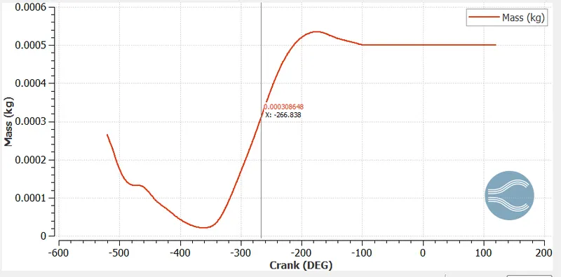
`mu_v = 0.000534/(1.225*0.0005171)`
`mu_v = 0.8430268 = 84.302%`
4. Measure the air mass flow rate for this engine in kg/s.
Mass of the air with the crank angle was given from the below graph = 0.0005341 kg.
Speed of the engine(N) = 3000 rpm = 3000/60 rps = 50 rps
The mass flow rate of air into the cylinder per 1 cycle ie, for 360 deg.
Then, the actual angle covered in 1 second is 50*360 = 18000 degrees
We know that the mass of air entering at 720deg = 0.0005341 kg
The mass flow rate of air in kg/s = rps x mass enter per rotation(360deg)
= `50*(0.0005341/2) = 0.01335 (kg)/s`
5.Why is the cell count varying during the simulation?
The cell count is varying because of adaptive mesh refinement(AMR) and fixed embedding. In AMR the velocity and temperature are used in the PFI. Fixed embedding refines the cells at particular regions or parts of the geometry where the data is to captured accurately. This embedding may be kept in cyclic or permanent mode.
6. In a real engine, valves are in contact with the cylinder head but while running simulation, there is a small gap:
- Why?
There is a small gap between the cylinder head and the valves during simulation because to remove the intersecting triangles. In the engine geometry, the valve spring and retainer assembly between the cylinder head and valves are not created so we leave a small gap.
- What happens if this gap is big?
The smaller gap gives accurate results but consumes more time. If we increase the gap between the valves and cylinder head, the solution will less accurate but faster. And the bigger gap increases the temperature in the cylinder which leads to knocking. The production of emissions also increases which leads to a decrease in the engine span and efficiency.
7. How many seconds does combustion last in this case?
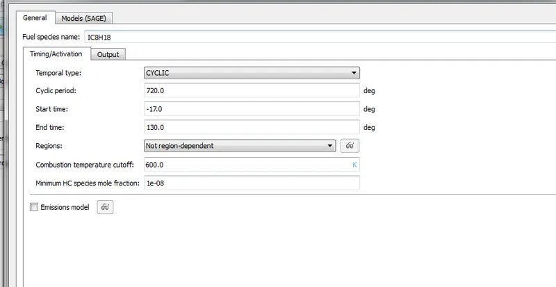
The duration of combustion in one cycle is 240-degree crank angles. This can be obtained from the engine performance calculator. So, converting the duration of combustion from degrees to seconds. The rpm of the engine is 3000.
Therefore, the degrees of rotaion per second of the engine (rpm ÷ 0.16667 = deg/s)
= 3000/0.1667 = 18000 degrees.
Therefore, the time for which the combustion lasts
= (degree of crank angle of combustion)/(degree of rotation per second of the engine)
= 240/18000 = 0.0133 seconds.
Diesel engine:
1. Advantages of Sector simulation:
sector simulation is a closed cycle simulation where intake and exhaust processes are not simulated, only the compression and power strokes are simulated. The major advantage of the sector simulation is only a sector(portion) of a combustion chamber is simulated. Since it is a closed cycle simulation, the number of cells and boundary conditions are minimized. So, it leads to accurate results in a low time.
2. When will the sector approach not work?
The sector approach doesn't work for open and unsymmetric cases. In the open case or cycle simulation, the intake and exhaust valves are open and they required to be modeled. The position of the valves varies with time, the sector approach fails to capture the effects of the valves. This occurs due to the sector approach, the injector is supposed to be symmetric about the center axis of the engine. So, the sector approach is applied only for closed and axisymmetric cycles.
3. Start crank angle and End crank angle:
Crank angle is the range of rotation of a crankshaft measured from the position in which the piston is at its higher point known as a Top dead center(TDC) and the piston is at its lower point known as a Bottom dead center(BDC).
We can choose the start crank angle(SCA) at the beginning of the compression and End crank angle(ECA) at the end of the power stroke. That means the SCA starts at 180 degrees and the ECA will end at 540 degrees.
4. Can we convert the PFI case into a SECTOR case? Explain your answer?
No, we can't convert the PFI case into a sector case. PFI stands for Port fuel injection. In PFI the fuel is injected through the injection port which is located on the intake port and rejected from the exhaust ports. In the PFI case, there are inlets and outlets which cannot allow a sector simulation(This is a closed cycle simulation where intake and exhaust processes are not simulated, only the compression and power strokes are simulated, this is only used in closed and symmetric case). And the PFI is an unsymmetric case. So, we cant convert a PFI case into a sector case.