Final Project: Design of an Electric Vehicle
AIM
Create a MATLAB model of electric car which uses lithium ion battery and induction motor. Choose suitable blocks from Powertrain block set. Prepare a report about your model including following:
Objectives:
1. System level configurations
2. Model parameters
3. Results
4. Conclusion
Electric vehicles have low running costs as they have less moving parts for maintaining and also very environmentally friendly as they use little or no fossil fuels (petrol or diesel).
While some EVs used lead acid or nickel metal hydride batteries, the standard for modern battery electric vehicles is now considered to be lithium ion batteries as they have a greater longevity and are excellent at retaining energy, with a self discharge rate of just 5% per month.
Despite this improved efficiency, there are still challenges with these batteries as they can experience thermal runaway, which have, for example caused fires or explosions in the Tesla models, although efforts have been made to improve the safety of these batteries.
To make a most simple and low run time vehicle model using individual componentsmodels
To check out the performance of the parameters like speed,state of charge(SOC),current..etc with various drive cycles,here drive cycle means it various the speed vs time as we give the input in the data of speed vs time in drive cycle.
To play with the motor power ,vehicle body (Rolling Resistance,Airdrag,weight) inputs .
To know the matlab models and how to configuration to match with actual vehicle.Let us consider a model in this report, an electric vehicle with a Induction motor and battery system using the SIMULINK
- EVs have no need for the fuel engine and gear transmission, the two of the most crucial components for internal combustion vehicles.
- An electric powered car has three primary components - Battery, motor controller, and the electric motor.
Model of ELECTRIC VEHICLE DESIGN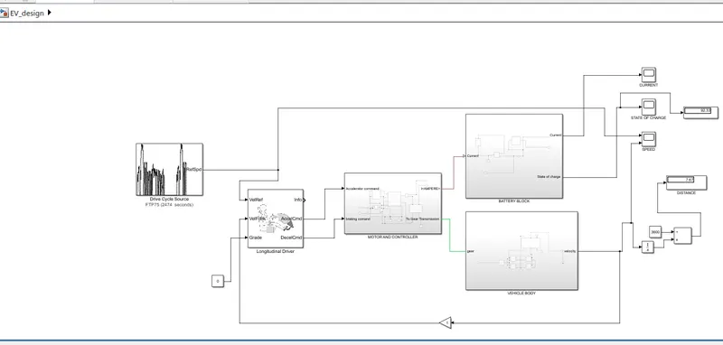
(1) Battery : The battery of an electric car can be charged through the use of ordinary grid electricity at a specialized power station. But aside from the conventional lithium-ion battery technologies, there are also other major battery technologies which can be used for electric cars.
- Lithium-Ion Batteries : This battery technology gives extra performance and range. However, it also carries the highest price tag. Lithium-ion batteries are lighter than Lead acid and Nickel metal. These are also the batteries used in digital cameras and smartphones.
- Lead Acid Batteries : This battery technology is the most popular. It is also the cheapest among the battery technologies. What’s good about it is it’s 97% recyclable.
- Nickel Metal Hydride Batteries : This battery technology provides higher output and better performance but it costs much more than lead-acid batteries.
(2) Motor Controller : The motor controller of an electric car administers its complete operation and the distribution of its power at any given moment. It acts as a floodgate between the motor and batteries. It helps monitor and regulates all key performance indications such as the vehicle’s operator, motor, battery, and accelerator pedal. It has a microprocessor which can limit or redirect current. It is used to either improve the mechanical performance of the car or suit the operator’s driving style. There are also more refined controllers which are capable of greater accuracy and thus, higher efficiency.
(3) Electric Motor : Unlike a gasoline engine with lots of moving parts, a motor only has one moving part. This makes it a very reliable source of motive power. Choosing an electric motor depends on the car’s system voltage. They can be structured to use either AC or DC current. AC motors are less expensive and lighter compared to DC motors. They are also more common and they tend to suffer from less mechanical wear and tear. However, AC technology requires a more refined or sophisticated motor controller.
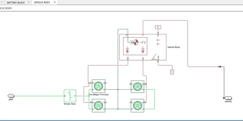
- accounts for body mass, aerodynamic drag, grade,externally-defined mass and center of gravity of the vehicle body.
Input Ports:
- W - Wind Velocity in m/s
- beta - Grade angle in radians
Output Ports:
- V - Velocity in m/s
- NR - Normal force on Rear Axle (N)
- NF - Normal Force on Front Axle (N)
Vehicle Body Parameters:
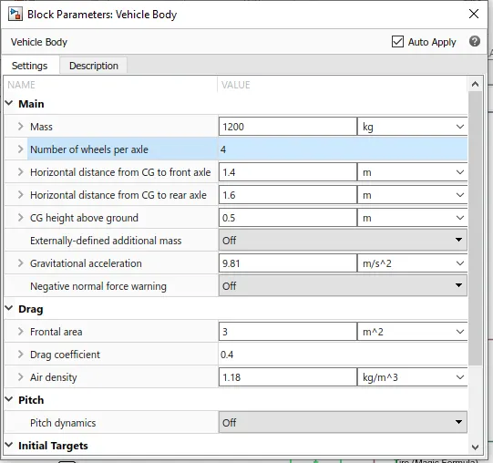
- Vehicle body mass, Centre of gravity distance values and aerodynamic drag variables are modified.
- Pitch dynamics are kept ON with other variable values as default values.
Tires

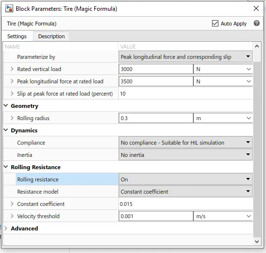
- The tires are parameterized by Peak longitudinal force and corresponding slip.
- The other block parameters such as - rated vertical load, peak longitudinal force at rated load and slip at peak force at rated load - are kept with their default values.
- The tire radius is given as 0.3 m.
- The tire inertia is kept as 1 kg-m^2. Also, the rolling resistance is given with a constant coefficient of 0.015.used to model a tire with longitudinal behavior given by equation based on four fitting coefficients.
- The block can model tire dynamics under constant or variable contact surface conditions.
Input Port:
- N - Normal force acting on tire, positive when force is acting downwards/towards the contact surface,
Output Port:
- S - Slip value relative to tire and surface of contact.
Conserving Ports:
- H - represents wheel hub which transmits thrust generated by the wheel to the body of the vehicle.
- A - represents axle on which the tires are mounted.
Gear

- A simple gear block is used to connect the motor to the rear axle of the vehicle.
- It represents the gearbox which connects the input shaft to the base gear and ouput from the foller gear.
Conserving Ports:
- B - port associated with input shaft (motor shaft)
- F - port associated with ouput shaft (axle / differential)
Simple Gear Parameters:
- Gear ratio and output direction is modified.
- Meshing loss is kept constant and gear is having a constant efficiency throughout the simulation.
- Viscous losses and faluts are kept at default conditions.
- The gross weight is given to be 1200 kg.
- The geometric parameters of the vehicle are given as -
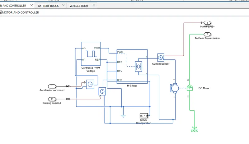
DC Motor
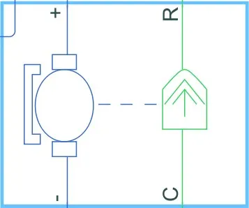
- Simulink provides an inbuilt bodel block for DC motor which converts electrical input into mechanical rotational output.
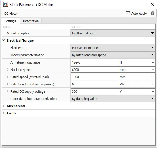
Note : Here, the blue colour corresponds to the electrical side of the motor and the green colour corresponds to the mechanical side. - Here, the motor field type is kept as Permanent magnet and the model parameterization is done by rated load and speed.
The armature inductance and the mechanical parameters are given their default values.
All the other parameters are changed as shown below
- The connection R represents the Rotor (rotational output) while the connection C is for the Casing (stationary). Thus, the R port is connected to the input of the vehicle subsystem created earlier. The C port is connected to a mechanical rotational reference.
- The + and - terminals of the motor are connected to the motor controller. If these terminals are directly connected to a battery, the required DC motor will run on the rated capacity of the battery. This will eventually result into no control over the DC motor and the vehicle will run at top speed throughout the simulation.
Thus, a motor controller is very much needed.
This is the DC Motor which would give the rotational power to the wheels and become the solar power generation source.
The DC Motors terminals are connected as mentioned below,
+ = Electrical signal to the motor Positive Terminal
- = Electrical signal to the motor Negative Terminal
R = Casing of the Motor connected with the Mechanical Rotational Reference Block
C = Rotor Case connected to the Mechanical Rotational reference
The parameter considered are, The Armature inductance is as default, varied the changes in the No-Load Speed @ 6000 rpm, the rated speed @ 4000 rpm, the Rated Load at 80kW, and the Rated DC Supply Voltage @ 500 V. All other parameters are as default.
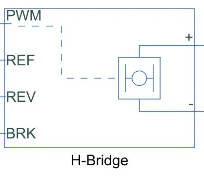
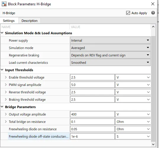
The H-Bridge helps in controlling the power that is input according to the requirement. The output provided are converted voltage as per the controlled parameters.
This block represents an H-bridge motor drive. The block can be driven by the Controlled PWM Voltage block in PWM or Averaged mode.
In PWM mode, the motor is powered if the PWM port voltage is above the enabled threshold voltage.In Averaged mode, the PWM port voltage divided by the PWM signal amplitude parameter defines the ratio of the on-time to the PWM period.
Connection REF is for the reference input. This combined with the PWM connected will form the pulse input for the H-Bridge.
Here, the REF input is connected to the Electrical Reference (ground).
Connection REV corresponds to the reverse motion of the motor which essentially means, the backward motion of the vehicle.
Here, the backward motion of the vehicle is not accounted for and so, the port is connected to the electrical reference.
Connection BRK is for the braking of the vehicle.Since, the PWM mode results in a huge amount of simulation time, Averaged mode is selected for this simulation.
Load current characteristics are considered to be smoothed here. Also, the regenerative braking is anabled for the simulation. This means, when the vehicle starts decelerating, corresponding amount of charge will be fed back to the battery.
Accordingly, the BRK input is connected to a Controlled Voltage Source. This will generate emf corresponding to the intensity of brakes applied and fed the power back to the battery.
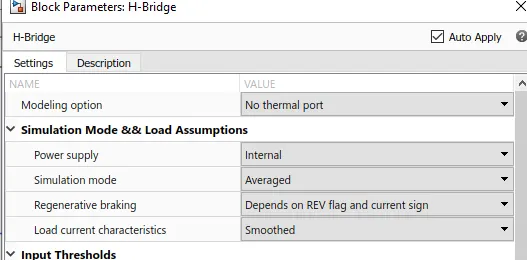
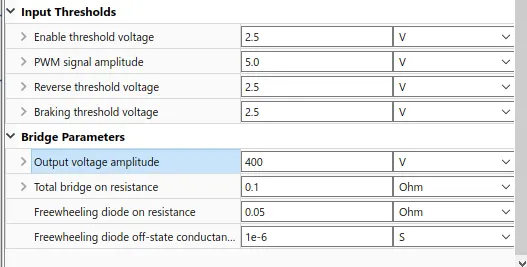
The Input Threshold parameters are left with their default values and The Output Voltage Amplitude of the H-Bridge circuit is given the same value as the rated DC supply voltage of the DC motor.
Controlled PWM Voltage
Simulink provides an inbuilt Controlled PWM Voltage block. This block is used for providing the proper pulse inputs to the H-Brdige circuit.
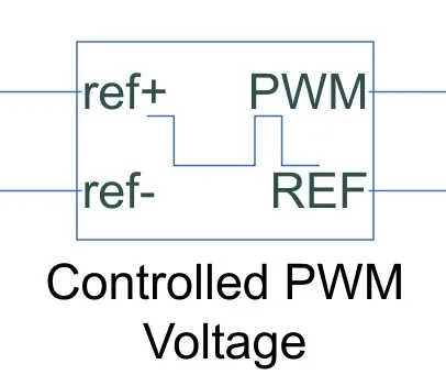
The Controlled PWM Voltage Block helps in keeping the Modulated Pulses as per the required pulses. So that the operations happens smooth and higher variations are not observed.
The Ports are connected as follows,
ref+ = Reference Positive connected with the Acceleration Commands from the Driver Model
ref- = Reference Negative connected with the Deceleration Commands from the Driver Model
PWM = PWM connected directly to the H-Block
REF = REF connected directly to the H-Block
- The PWM & REF connections are for the corresponding ports on the H-Bridge circuit.
The 2 reference inputs correspond to the throttle inputs given by the driver. The block generates corresponding pulse width as per the accelerations and brakes apllied by the driver himself. - Here, the PWM frequency is 5000 Hz. Also, the simulation mode is Averaged as that in the H-Bridge circuit.
Note :The parameters are set as default.
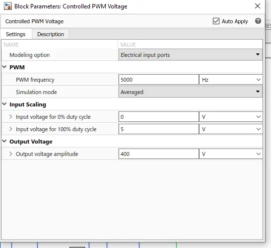
- The input scaling parameters given are -
0V for 0% duty cycle and 5V for 100% duty cycle. Accordingly, the output voltage amplitude becomes 5V. - The H-Bridge circuit along with the PWM input, together form the motor controller circuit.
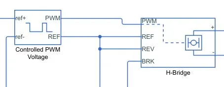
-
Longitudinal Driver :
- Longitudinal Driver is an inbuilt block provided by the powertrain blockset.
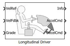
- It is a parametric longitudinal speed tracking controller for generating normalized Acceleration and Braking commands based on reference and feedback velocities.
- The VelRef port is the reference velocity port where the input drive cycle data is fed.
The VelFdbk port corresponds to the feedback velocity. The actual velocity output given by the vehicle body is connected here. By comparing the actual (feedback) velocity with the reference velocity, the driver block generates acceleration and braking signals in order to minimise the error between the two concerned velocities.
Grade corresponds to the grade angle. For this simulation, no inclination is considered and hence, a constant block with value 0 is connected.
Info gives the output for the bus signal for different block calculations like difference in reference vehicle speed and vehicle speed, etc.
AccelCmd & DecelCmd correspond to the acceleration and deceleration commands generated respectively and are connected to the corresponding ports of the Controlled PWM Voltage block. - Here, the selected control type is PI. Acordingly, the block implements proportional-integral (PI) control with tracking windup and feed-forward gains.
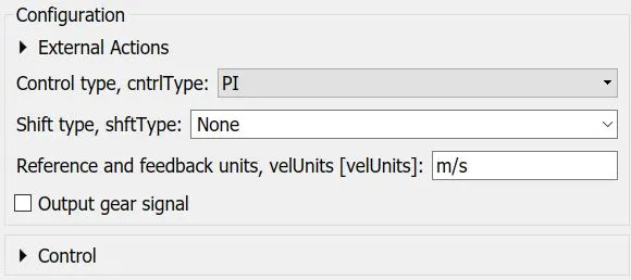
- Longitudinal Driver is an inbuilt block provided by the powertrain blockset.
Battery Source
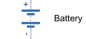
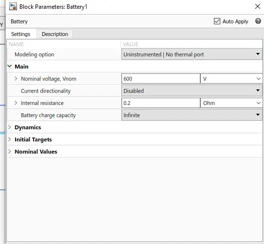
- To model the Battery pak, a simple Battery block is used. This is because, if the generic battery block is used instead, the simulation will run for a much longer time.
- Here, the selected option for Battery Charge Capacity is Finite. Accordingly, the block models the battery as a series internal resistance plus a charge-dependent voltage source.
If the chosen option had been Infinite, the voltage source would have been constant. - Also, the self-discharging of the battery and the battery dynaics are disabled.
- The Battery Nominal Voltage is given as 600V.
The Ampere-hour rating is assumed to be 50.
The rest all paramaters are left with their default values
The battery is connected as the power source to the model so that the power could be generated and the same power is transmitted accordingly to all the operating sources.
The terminals connected are to,
+ = The positive terminal of the operating sources
- = The negative terminal of the operating sources.
The paramters considered of the battery are -
The battery Nominal Voltage is rated as per 600 Volts,
The internal resistance is as per 0.2 Ohms and others set as default.
Reference Velocity (Drive Cycle) :
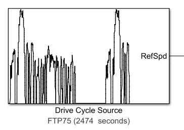
- The Drive Cycle Source block is used to provide the reference speed for the simulation.
- It generates a standard or user-specified longitudinal drive cycle.
-
The Driver Model has the Input and Output Ports which are connected to the following,
Velocity Reference - Drive Cycle
Velocity Feedback - Distance Calculation
Grade - Constant 0
Info - Not Connected
Acceleration Command - Controlled PWM Source
Deceleration Command - Brake in H-Bridge to maintain the speed according to the Drive Cycle.
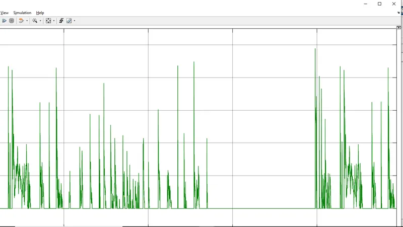
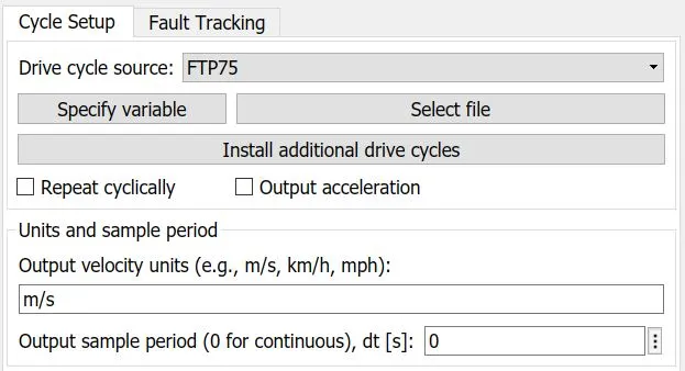
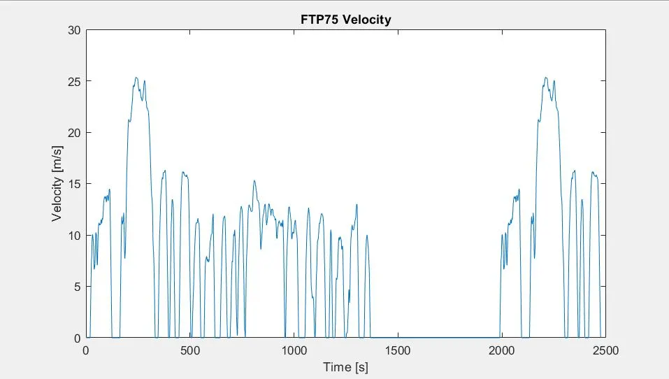
- Here, the selected drive cycle is the standard FTP75.
- The plot of the drive cycle is shown below -
Battery State of Charge :
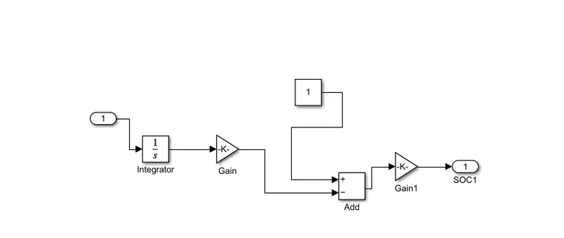
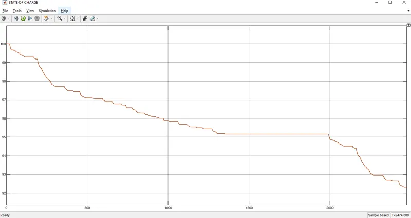
- A small subsystem is created to calculate the State of Charge of the battery.
- This subsystem takes the battery current as the input.
- The essential process to calculate the SOC is by subtracting the charge from the rated capacity of the battery.
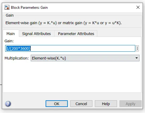
- Accordingly, the current is integrated w.r.t. time to get the charge in coulumbs. Now this coulumb value is modified into Ampere hours.
This value is now subtracted from the charging capacity of the battery - Finally, the remaining charge is now converted into percentage value of the charging capacity of the battery.
Simulation :
- The system is ran for simulation for 2474 s which is the total time for which the input drive cycle is defined.
- A Solver Configuration is added to ensure proper solving of the mathematical equations by the model.
- Scopes are connected to analyze different outputs such as the SOC of the battery, the reference velocity & the actual velocity of the vehicle and the distance covered by the vehicle during the total run.
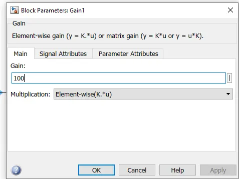
- The 2 velocities are first converted from m/s to kmph values. For this, simple Gain blocks are used.
- The distance is calculated by simply time-integration of the vehicle velocity.
OUTPUTs
Speed OUTPUT
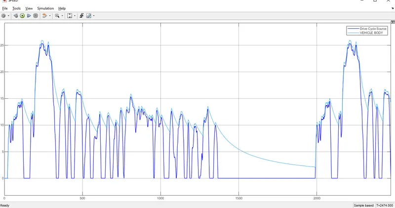
- As can be seen from the above picture, the actual velocity of the vehicle differs from the reference drive cycle velocity.
- This is because, the chosen battery capacity and motors are not able to propel the speed upto the required extent.
- If a battery of higher capacity is chosen, the actual velocity will tend to match with the reference velocity.
- Also, it may be noted that in certain regions, despite the drive cycle showing small decelerations, the vehicle actually is accelerating with decreasing magnitudes. Reason being the same.
State of charge output
current output