Project 2 - Modeling of 3 phase Induction Motor Drive
Aim: To Model 3 Phase Inverter using Simulink (model the parasitic as well) with a switching frequency of 10Khz using 3 phase Squirrel Cage Induction motor, using the V/F method, open loop
Given Parameters
- Power = 100 HP
- DC Voltage = 800 V
- Output Voltage = 460 VRMS – line to line
- Initial Speed = 1500 RPM
- Final Speed = 1000 RPM
- Initial Load Torque = 10 Nm
- Final Torque=20 Nm
- Torque Step Time = 0.1 secs
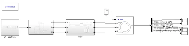
let us model the Three-phase inverter for a three-phase squirrel cage Induction motor using the V/F method in the Simulink
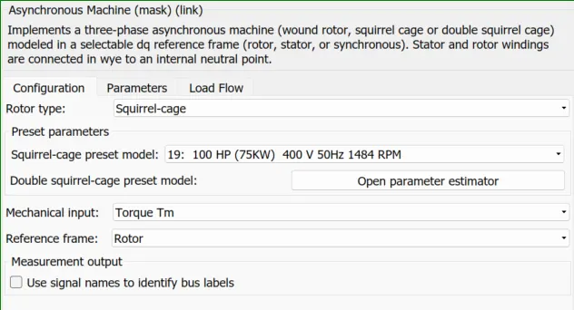
let us see the motor parameters
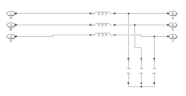
the filter and the parasitic capacitance are shown as
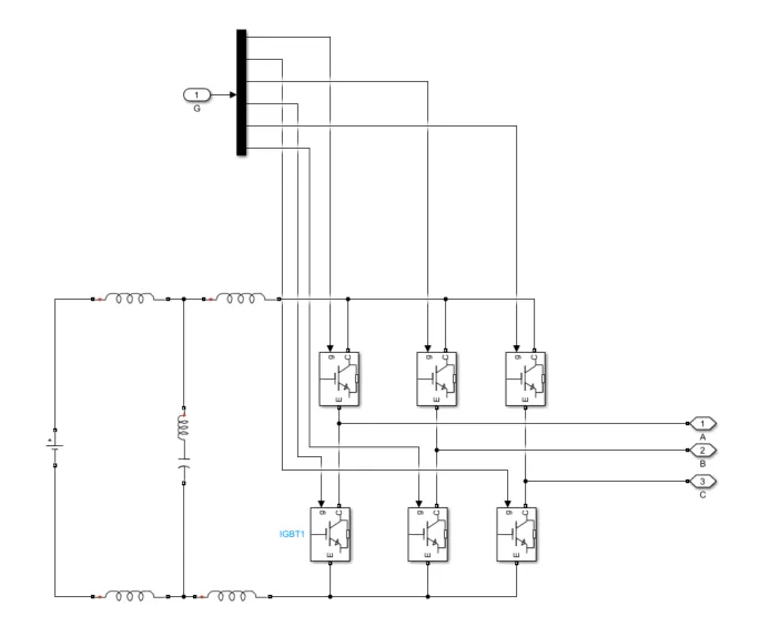
let us see the converter in which the switching frequency should be 10kHz and also the operating voltage 800V and also 100Hp which is equal to 75kW so the switching device is selected as IGBT.
The DC Link Capacitor with ESL is connected across the source, and the Bus bar inductor and loop inductor are also considered. All these components minimize ripple content and filter for minimize transient behaviour
let us see the converter
The controller is a V/F-based controller in which the voltage and frequency are altered and fed to sine pwm which will generate gate pulses according to the following logic
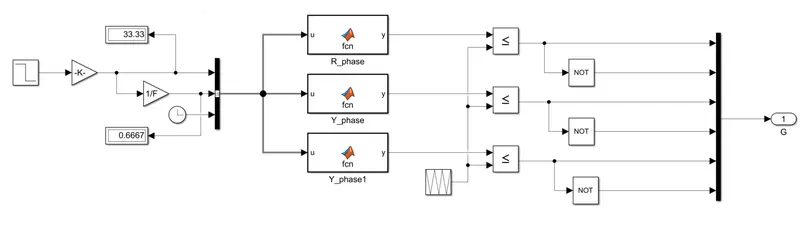
the reference speed is given in terms of RPM which is converted into frequency and fed into the voltage phase delayed functions so that it can create 6 pulses using the above logic
let us see the results of the speed and torque of the motor
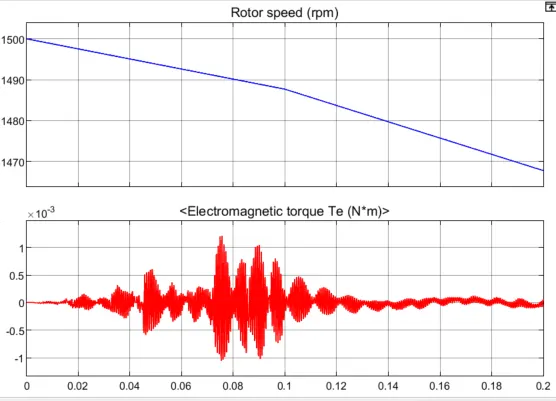
we can observe the initial speed is 1500rpm and the initial torque is 0, The torque increases the speed decreases we can observe the inverse operation between the torque and speed characteristics of a three-phase squirrel cage induction motor
Aim 2: To Use the 3-phase inductor motor theory to derive the transfer function of 3 phase Induction Motor
The transfer function of an Induction motor will be determined as follows
Mathematical modeling of induction motor can be obtained by taking all the basic equations
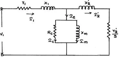
`r_1=" resistance of Stator"`
`X_1="Stator leakage reactance"`
`I_1=" stator current"`
`R_c=" shunt branch resistance"`
`X_m=" magnetizing reactance"`
`I_e=" per phase no-load current"`
`I_2=" Rotor current"`
`I_2'=" Rotor Current per phase referred to stator"`
`X_2'=" standstill rotor reactance referred to stator"`
`r_2'="rotor resistance referred to stator"`
`V_1="Stator Voltage"`
`E_1=" stator induced emf"`
`s=" slip"`
The electrical equation of the machine is
`V_a=I_aR_a+JX_sI_a+E_b`
where `E_bprop(d theta)/(dt)`
Applying Laplace transforms,
`V_a(s)=I_a(s)(R_a+jX_s)+E_b(s)`
we know that
`E_b=K_tstheta(s)`
substituting, we get
`V_a(s)=I_a(s)Z(s)+K_tstheta(s)`
`=>(V_a(s)-K_t(s)stheta(s))/(Z(s))=I_a(s)`
Electrical Torque is given by
`T_e=E^2sintheta`
Mechanical Torque is given by
`T_m=Jddottheta+Btheta`
Taking Laplace Transforms,
`T_m(s)=(Js^2+Bs)theta(s)`
`T_m=T_e=>E^2theta(s)=Js^2+Bs(theta(s))`
`=>(Js^2+Bs-E^2)theta(s)=T_m`
`=>Js^2+Bs-E^2=T_m/(theta(s)`
`=>(theta(s))/(T_m(s))=1/(Js^2+Bs-E^2)`
we know that `T propphiI_acostheta ("take "theta=0)`
`T=KphiI_a`
`=>T=Kphi(s)I_a(s)`
From above we know `(K_a[V_a(s)-K_tstheta(s)])/(Z(s))=(Js^2+Bs-E^2)theta(s)`
`=>K_aV_a(s)=(Js^2+Bs-E^2)theta(s)Z(s)+K_tstheta(s)`
`=>(V_a(s))/(theta(s))=((Js^2+Bs-E^2)Z(s)+K_aK_ts)/K_a`
`=>(theta(s))/(V_a(s))=K_a/((Js^2+Bs-E^2)Z(s)+K_aK_ts)`
`=>(theta(s))/(V_a(s))=K_a/((Js^2+Bs-E^2)(R_a+L_as)+K_aK_ts)`
The transfer function of the induction motor is given as
`=>(theta(s))/(V_a(s))=K_a/(JL_as^3+(R_aJ+BL_a)s^2+(BR_a+K_aK_t)s)`
Aim 3: To Model 3 phase induction motor with a 3-phase inverter using Direct Torque control using an Average Model, and To Implement both torque and flux control to achieve the desired power
let us design the direct torque control of 3 phase induction motor in Simulink
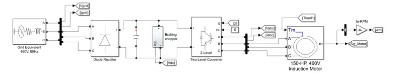
The three-phase voltage source is fed to the diode rectifier to convert 3 phase to a DC Voltage Source three-phase two-level inverter is connected to the dc voltage source and then connected to the induction motor here the DC source is charged from the grid equivalent and then discharged by the 3 phase inverter to achieve this a breaking chopper is added which is shown below
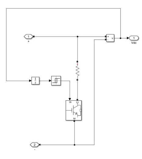
this breaking chopper avoids the crossover operation of the rectifier and the inverter
let us see the controller
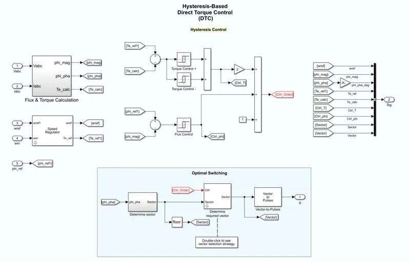
The hysteresis Based Torque controller uses the reference speed reference angle and also reference torque which are converted into ABC and then to magnitude and angle so then we can apply inverse park transformation to convert them to sectors and then the logic is applied so that it can create the vectors the vectors are then converted to pulses
the generated pulses are needed to the inverter so that it can convert the DC voltage to the required/desired Three phase voltage that can feed the Three phase induction motor
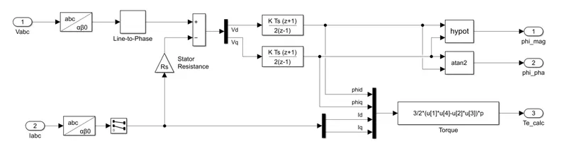
the flux and the torque are calculated by the required equations as shown above ABC is converted to alfa beta by using Clark's transformation then the desired calculations are made to generate the flux control and Torque control outputs
let us see the output results
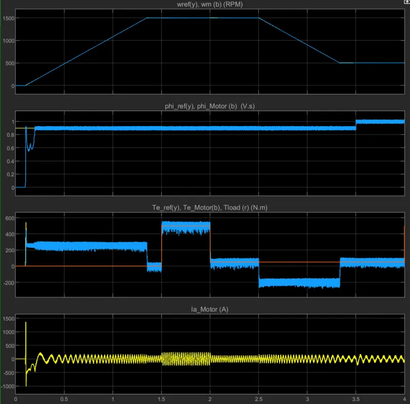
we can observe the flux and torque and the speed of the induction motor is controlled
Conclusion: The Three Phase induction motor Drive is modeled and controlled using both the V/F control method and the Direct Torque Control Method and also the Transfer Function of the Induction motor based on the Equivalent Circuit is determined.