Project-1: Powertrain for aircraft in runways
Part A
1. List out the total weight of various types of aircrafts.
The weight of the aircraft is needed to be calculated by the pilot for every flight to ensure the aircraft remains within weight limitations set by the manufacturer .These limitations are to ensure the aircraft is able to perform and recover from all flight maneuvers and withstand structural loading.
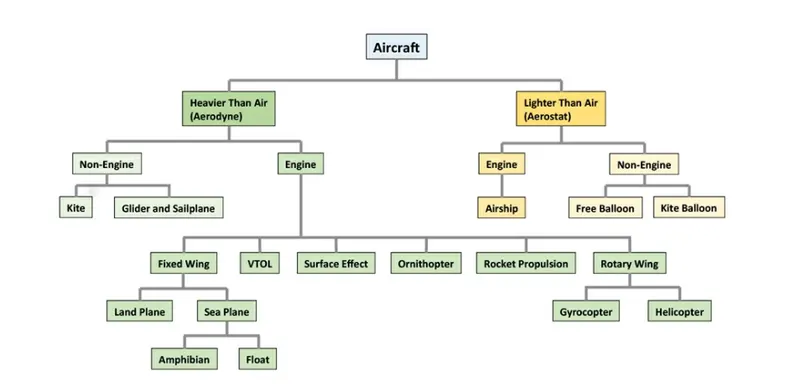
For example
The boeing 737 aircraft can weigh from 132,000Lbs/60,000kg to 187,000Lbs/85,000kg at take off it depending on the model of the aircraft.As compared with the a small Cessna 172 aircraft weighing around 2,4000Lb/1,11kg.
An aircraft's empty weight,fuel,passengers and cargo must not weigh more than the aircraft's Maximum Gross Take off weight.
The Various types of Airplane weights
|
Aircraft |
Total Weight (Take-off Weight ) |
Eg: Boeing 737-800 |
80,000kg |
Eg: Boeing F-18 Hornet |
113,646kg |
Eg: Airbus A300 600F |
165,900kg |
Eg: Boeing RAH-66 Comanche |
7,791kg |
Eg: Bell 212 |
5,080kg |
Eg: Grand Caravan EX |
3,994kg |
Eg: Bell Boeing V22 osprey |
27,445kg |
Average sized airplane Fighter jet
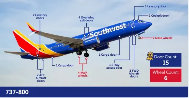
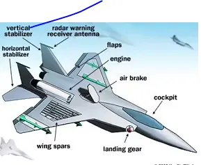
Cargo planes Military helicopter
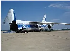
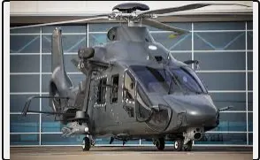
Mid size Helicopter Turbopop aircraft

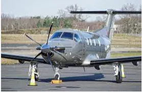
Convertiplanes
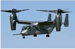
What Do Aircraft Weight Names Mean?
You may have been looking at the table above and thinking the numbers don’t work out because if you took the Aircraft Empty Weight and added the Maximum Fuel Weight and Maximum Cargo it could carry, it could be well over the aircraft’s Maximum Gross Weight.
Aircraft Empty weight
This is sometimes referred to as OEW – Operating Empty Weight and it is the weight of the aircraft with all its equipment on board but no fuel, no passengers or no cargo.
Think of this like the aircraft has just come out of the factory and is sitting waiting to be fueled up for delivery to the customer.
Aircraft Maximum Gross Takeoff Weight (MGTW)
This is the maximum permissible weight the aircraft can weigh as it lifts off the ground at takeoff. This includes the aircraft’s empty weight, the fuel, the crew, the passengers, and all the cargo.
This weight limit is set by the manufacturer and is gospel. Many aircraft accidents have been caused by an aircraft being overweight and the pilot/s have not had enough power or maneuverability to prevent the accident.
Aircraft Useful Load
This is the weight that a pilot can place in the aircraft. Take the MGTW figure and subtract the AEW and this is the total useful load that can be placed into the aircraft. This is the fuel, crew, passengers, and cargo. The bigger the load, the more useful the aircraft can be to its customers!
How Fuel, Passengers & Cargo Affect Aircraft Weight
Each item of weight added to the aircraft has to be accounted for and some items can be left off the flight and others not so much. There are several scenarios we can look at, and for these examples, I will use the Astar helicopter I fly, as it is really easy for me to work out the numbers
Usually, the passengers and their cargo need to go as they are the ones doing the work, so fuel has to be reduced. Instead of filling the aircraft fuel tank up to 100%, I can only fill it to around 60% to keep the aircraft under its MGTW.
2. Aim : Difference between airspeed and ground speed
Ground speed
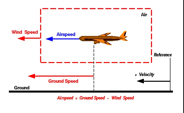
Ground speed is the horizontal speed of an aircraft relative to the Earth’s surface.[1] It is vital for accurate navigation that the pilot has an estimate of the ground speed that will be achieved during each leg of a flight.
An aircraft diving vertically would have a ground speed of zero. Information displayed to passengers through the entertainment system of airline aircraft usually gives the aircraft ground speed rather than airspeed.
Ground speed can be determined by the vector sum of the aircraft's true airspeed and the current wind speed and direction; a headwind subtracts from the ground speed, while a tailwind adds to it. Winds at other angles to the heading will have components of either headwind or tailwind as well as a crosswind component.
Airspeed
An airspeed indicator indicates the aircraft's speed relative to the air mass. The air mass may be moving over the ground due to wind, and therefore some additional means to provide position over the ground is required. This might be through navigation using landmarks, radio aided position location, inertial navigation system, or GPS. When more advanced technology is unavailable, an E6B flight computer may be used to calculate ground speed. Ground speed radar can measure it directly.
Ground speed is quite different from airspeed. When an aircraft is airborne the ground speed does not determine when the aircraft will stall, and it doesn't influence the aircraft performance such as rate of climb.
3. Aim : Why is it not recommended to use aircraft engine power to move it on the ground at Airport
The High engine thrust during maintenance activity can cause considerable damage to airplanes and other elements in the airport environment. An example of this problem occurred after an airplane arrived at its final destination with a log entry indicating the flight crew had experienced anomalous engine operation.
We are assuming passenger commuter aircraft and large airliners. Aircraft move using their own engine power all the time on the airport apron and taxiways under their own power to go towards runways and after landing taxi to their assigned gate.
The only time they use external assistance is to pushback from the gate. Large turbofan aircraft need help to reverse via a pushback tractor. The engines are turned on after the pushback is complete and the aircraft can move forward under It’s own power.
To be accurate, some aircraft can reverse using a variable pitch prop or thrust reversing on turbofans but generally reversing is done via pushback tractors. Blasting jet reversers blows debris In the crowded gate area creating foreign object damage hazard for adjacent aircraft, gate equipment or terminal waiting area glass windows.
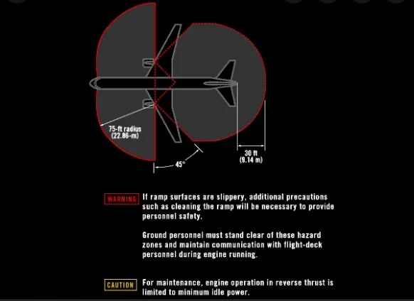
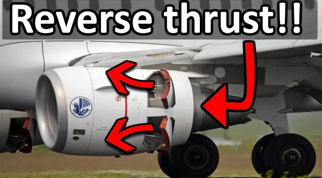
An Airplanes move on the ground the same way they move through the air: Using the thrust generated by their turbine engines. The wheels turn freely and merely support the weight of the plane.Engine power is used all the time to move aircraft on the ground. The engine power is used all the time in the ramp. They do get pushed back because only aircraft with engines on the tail can power-back due to FOD.
4. Aim: How an aircraft is pushed to runway when its ready to take off
Aircraft get pushed back
An Airplanes have engines, and they can use them to move forward along the ground. So they push themselves to the runway.It is true that most of the time, a small vehicle is needed to push the larger commercial airplanes backwards away from the terminal building, because even if a plane can reverse it’s thrust, it’s not always safe to hit the buildings with that reverse thrust. So the little trucks push the bigger planes back away from the buildings, but after that, the planes can apply a small amount of engine power to roll forward just as all airplanes can.Aircraft push themselves to the runway.
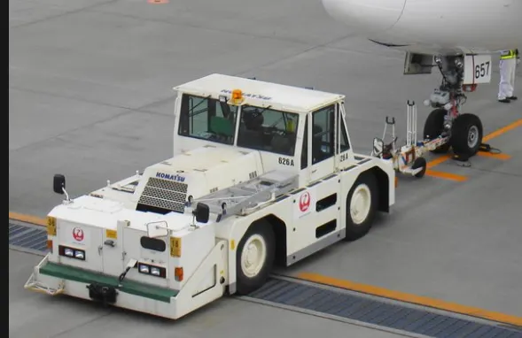
Large jetliner passenger aircraft are pushed away from the passenger loading gate by a tug. This is a machine with wheels, some form of power such as an internal combustion engine, or a battery. When the large aircraft is being pushed backwards, there is someone on each wing tip. They are looking out to make sure nothing will touch the aircraft. The whole idea is to avoid expensive crunching noises.
It means that the movement of an aircraft from a noise in parking stand using the power of a specialized ground velhicle attached to or supporting the noise landing gear.Pushback is when an aircraft is pushed backwards away from the airport gate by velhicles called tugs or tractors.
When we are closure to departure,an aircraft tug will park right in front of the noise wheel.
The tug might be directly attached to the planes nose gear with a tow bar,or could be a 'wheel-lift' tug.These tugs cradle the nose gear,then lift it up before moving the plane,that gives the tug driver control over the plane's direction during pushback.
New taxi technologies are appearing ,like pilot controlled tugs,and electric motors mounted to the plane's landing gear .Both promise to save fuel and reduce airport noise.
How do planes get to the runway
An airplane uses taxiways to taxi from one place to another place for eg ,when it is moving from a hangar (a large building in an airport in which aircraft are kept) to the runway.
5.Aim : Learn about take off power, tyre design, rolling resistance, tyre pressure, brake forces when landing
Take off power
The take off power or power take off (PTO) is one of several methods for taking power from a power source ,such as a running engine and transmitting it to an application such as an attached to implement or separate machine.
The Take-off Power is the amount of power that an engine is allowed to produced for a limited period of time for take-OFF.The normal take-off is one in which the airplane is headed into the wind, or the wind is very light. Also, the takeoff surface is firm and of sufficient length to permit the airplane to gradually accelerate to normal lift-off and climb-out speed, and there are no obstructions along the takeoff path.
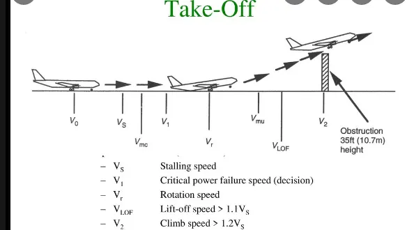
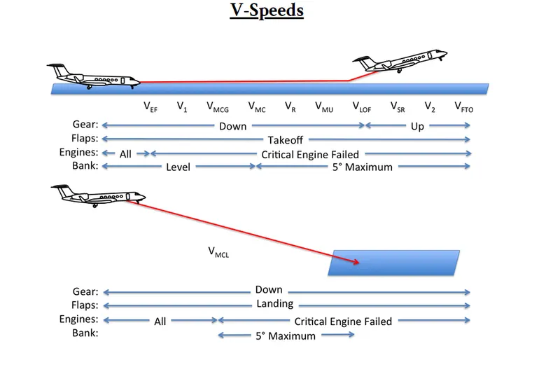
the airplane should be carefully aligned with the intended takeoff direction, and the nose wheel positioned straight, or centered. After releasing the brakes, the throttle should be advanced smoothly and continuously to takeoff power. An abrupt application of power may cause the airplane to yaw sharply to the left because of the torque effects of the engine and propeller.
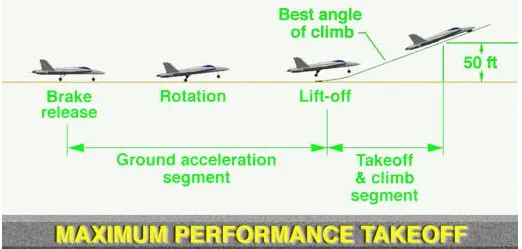
the airplane should be carefully aligned with the intended takeoff direction, and the nose wheel positioned straight, or centered. After releasing the brakes, the throttle should be advanced smoothly and continuously to takeoff power. An abrupt application of power may cause the airplane to yaw sharply to the left because of the torque effects of the engine and propeller.
There are two reasons for making a takeoff as nearly into the wind as possible:
- Aircraft speed will be less, therefore reducing wear and stress on landing gear
- Shorter ground roll and therefore much less runway length
For light aircrafts ,usually full power is used during take off .Large transport category (airliner) aircraft may use a reduced power for take off,where less than full power is applied in order to prolong engine life,reduce maintenance costs and reduce noise emissions.
Tyre Design
Designing aircraft tires is a very intense undertaking. The tyre is designed to withstand heavy loads while landing, take off, taxing, and parking. The number of wheels required for aircraft increases with the weight of the aircraft, as the weight of the aeroplane needs to be distributed more evenly. Aircraft tyre generates more heat during landing. Aircraft drags the wheel until they match the rotational velocity of wheels. Due to this heat generates. However, each tyre is built to operate within a given temperature. This is known as vulcanization temperature. During the course of its use, if the tire is heated past the vulcanization temperature, it begins to wear gradually.
Two types of tires are used in aircraft applications: bias-ply tires and radial tires.
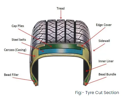
Radial Tyre: It has fibre strands of the ply fabric oriented at 90° to the direction of rotation and the tyre sidewall. This restricts flexibility bidirectional and the flexibility of the sidewall while it strengthens the tyre to carry heavy loads. Due to their unique construction most radial tyres are resistant to penetration ad cuts. Due to stiffer tread they distribute weight evenly. Thus provide greater traction. Radial tyres have an advantage in term of reducing the heat better.
Bias- ply Tyre : It has the fabric bias oriented with and across the direction of rotation and the sidewall. Since fabric can stretch on the bias, the tyre is flexible and can absorb loads. Tyre strength is obtained by adding plies. It is cut resistant is sidewall area. These tyres do not offer as much smoothness in terms of riding quality.
Tire Terminology:-
Ply Rating:- The ply rating is used to indicates an index to the load rating of the tire.When tires were made from cotton cord,ply rating did indicates the actual number of pilies in the carcass. with the development of highere strenght fibrics such as nylon. the ply rating has been replacedto mens an index of cascass strength the load carrying capacity.
Rated load:- This is a maximum allowable load that the tyre can carry at the specified rated inflation pressure.
Rated Pressure:- The rated pressure is the maximum inflation pressure to to match the load rating.Aircrafts tire pressure are given for an unloaded tire.The pressure are 4% as a result of a reduction in air volume.
Outside Diameter:- This measurement is taken at the circumferential center line of an inflated tire.
Section Width:- This measurement is taken at the Maximum cross sectional width of an inflated.
Ram Diameter:- This is the nominal diameter of the wheel on which the tire is mounted.
Section Height:- This measurement can be calculated by using following formulas,
Section Height= Outside Diameter-Ram Diameter/2
Aspect ratio:- This measure of the tire cross section shape, This can be calulate for following formulas,
Aspect ratio= Section Height/Section Width
Flange Height:- This is the height of the wheel rim flange.
Flange Diameter:- The Diameter of the Wheel including the flange.
Free Height:- This measurement can be calculated by using following formulas,
Free Height= Outside Diameter- Flange Diameter/2
Static Loaded Radius:- This is the mesurement from the center of the axel to the runway for a loaded tire.
Loaded Free Height:- This measurement can be calculate for following formulas,
Loaded Free Height=Static load radius-Flange Diameter/2
Tire Deflection:- It is used when talking about aircraft tires is the amount of deflection it see when rolling under load.The most aircraft tire are design to operate at 32% deflection. The tems % of deflection is a calculate using following formulas,
% Deflection = Free Height- Loaded free Height/Free Height
Service Load:- The load on the tire at maximum aircraft takeoff Weight.
Service Pressure:- The corresponding pressure to provide proper deflection at service load.
Rated Speed:- The Maximum speed to which the tire is quelified.
Tyre Size:-
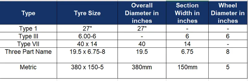
- The type I The very earliest of tyre designs and their outside diameter e.g. 27''
- The type III tyres are generallythe aviation and it include the most widely used sizes such as 5.00-5 and 6.00-6. These measurements refer to the section width of a tyre and also the rim ledge diameter (or the hole in the middle) hence a 6.00-6 is 6 inches wide and sits on 6-inch wheel.
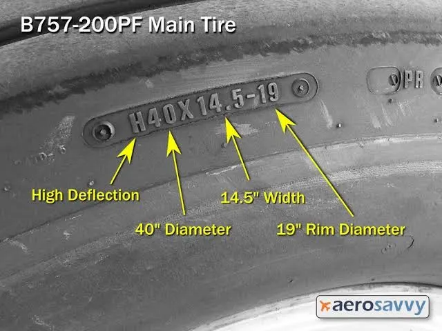
- Three Part Name Sizes cover most of today’s designs and typically describe the Outside Diameter, Section Width and Rim Ledge Diameter e.g. 15×6.00-6, the tyre is 15 inches tall, 6 inches wide and sits on a 6-inch wheel.The ‘H’ which identifies the tyre as having a higher percentage deflection.
- Metric sizes are the same as three part name sizes but the Overall Diameter and Section Width are replaced with millimeters but the rim sizes remain in inches, e.g. 380×150-5, its imperial equivalent is a 15×6.00-5.
- Radial tyres are also the same as three part name sizes but the dash preceding the rim diameter is replaced with the letter ‘R’ e.g. 32×8.8R16.
Rolling resistance
To determine the rolling friction of airplane wheels and tires under various conditions of wheel loading, tire inflation pressure, and ground surface. The effect of wheel-bearing type was also investigated. Six pairs of wheels and tires were tested including two sizes of each of the types designated as standard (high pressure), low pressure, and extra low pressure. The results of calculations intended to show the effect of variations in rolling friction on take-off are also presented.
- The force that resists the motion of a body rolling on a surface is called the rolling resistance or the rolling friction.it is also called as Rolling Friction force.
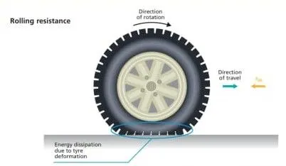
- Rolling resistance is the combination of forces that work against the forward motion of your vehicle. The weight of the vehicle, gravity and inertia, the amount of friction between the tires and the road surface, and air drag all play a part. The more rolling resistance, the more power it takes to propel a vehicle.
- There is a frictional force between the surface of the object and the rolling surface that cause the object to rotate.
- The frictional force is considered rolling friction. We can calculate that rolling friction as:-
Frr=Crr⋅F">Frr=Crr⋅F
Where,
Frr = is the rolling resistance friction
F = is the normal force
Crr = is the coefficient of rolling resistance friction
We have a coefficient of rolling resistance friction, which is a property of the relationship between the object's material and the surface's material. The Constant value of Crr table as shown in following:-
Tyre pressure
Tyre Pressure:-
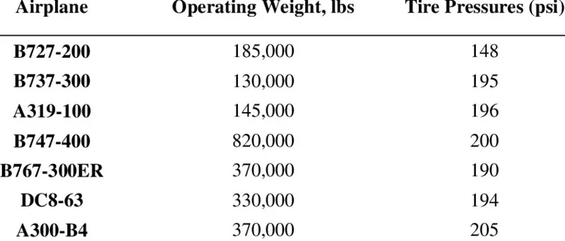
Tires are one of the most vitally important.The Aircraft generlly operate at High pressure.Upto 200psi. The 14 bar, 1400Kpa for Airlines.The high-flying rubber is typically inflated to 200 psi, roughly six times what you put in an automobile tire, and the tires on an F-16 fighter are pumped to 320 psi. A fully loaded 747-8 weighs nearly a million pounds. All that weight rides on a handful of tires. Automobile tires are pressurized to around 30-40 psi.
The Various type of Airplane and there Tire Pressure in Psi as shown in following:-
Brake force
Brake Forces when landing:-
The Braking System is one of the Crucial element in the aviation sector.The Advanced of technologies such as Thrust reversers,Spoilers,disc brake etc.Has transformed the commercial as well as military aviation extensivety.
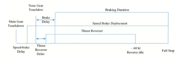
Their uses ensured better utilisation of energy.Which would otherwise go waste and also reduces the dangers of accident due to skidding and shock cooling.Now day the material thermal and mechanical properties are being used such as carbon fibre, ceramics etc.This ensures the longer life of brake and increased the realiability and Safety.
Aircraft brakes stop a moving aircraft by converting its kinetic energy to heat energy by means of friction between rotating and stationary discs located in brake assemblies in the wheels.
Spoilers:- The Spoilers that are used in flight as speed brakes as well as on landing.) While the spoilers provide some drag, their primary purpose is to stop the plane from actually flying, putting all of the weight on the landing gear and in turn making the brakes that much more effective.
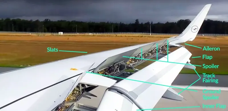
Fig:- Spoilers Speed Brake
- Thrust Reverse: that allow thrust from the engines to be used to slow the aircraft.
- Air Brake: It is dedicated flight control surface, that work by increasing drag.
Autobrakes:-
The Wheel brakes are usually selected to engage automatically after landing.The crew will decide which is the most appropriate to use for every landing depending upon factors like the length of runway, if it is wet or dry, or if the pilots want to exit the runway at a particular point. “For a short wet runway you might select autobrake 3, or MED on the Airbus. For a long dry runway you might select autobrake 1 or LOW on the Airbus,” his transition from autobrake to manual brakes can be quite difficult to do smoothly especially in a crosswind, as you will be steering the aircraft with the rudder pedals and then have to press down on the tops of the rudder pedals evenly to deactivate the autobrakes and start manual braking.
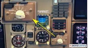
Fig:- Autobrake
Aircraft Brake system:-
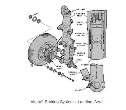
The Aircraft typically used disc and multi-disc brakes.This brake consist of rotating disc attached to the wheel assembly.the brake pad is made of material names as asbestos,ceramics, carbon.When brake pedal is pressed,The brake fluid under pressure flow from master cylinder to the slave cylinder via tubes.The piston forces the brake pad against the rotating part.The friction between the brake pad and disc surface,resist its rotating rotating motion and stop it.These day the disc are provided with slots for better heat dissipation at high temperature.
The kinetic energy (KE) is a function of mass (m) and velocity (v) according to the equation:-
K.E=12⋅m⋅v2">K.E=1/2⋅m⋅v2
Part B
6a) AIM :With necessary assumptions, calculate the force and power required to push / pull an aircraft by a towing vehicle
They are 3 types of forces will act on the aircraft
- Acceleration force
- Rolling Resistance
- Aerdynamic drag force
- Hill climbing force
Rolling Resistance
Rolling resistance is the force resisting the motion when a body rolls on a surface. It is the friction force that is needed to be overcome to move a vehicle.
The kinetic energy of the wheels is partially converted into heat. The rolling resistance is proportional to the normal force perpendicular to the rolling wheel and is approximated by the rolling resistance coefficient urr. Therefore, Equation that can be used for the rolling resistance force of the entire system is
Frr = urr * m * g
where, urr= Rolling resistance co-efficient (It depends on the tire material, tire structure, tire temperature, road roughness, road material etc.) m= Total mass of the vehicle (vehicle mass + payload) in kg G= gravitational constant , that is 9.8 m/s^2
Aerodynamic drag force
Aerodynamic drag force is the force which is required to keep a vehicle moving. There are two component of this force , one is shape drag (due to the shape of the vehicle) and another is skin friction (due to friction between air and skin of the vehicle).
When the vehicle moves the velocity of air near boundary is higher than the air surrounding. Both the tug and the aircraft will experience some aerodynamic drag. For completeness, the aerodynamic drag force caused by the aircraft and towing vehicle can be given by Equation below
Fad = (1/2) * ρ * V^2 * A * (Cd_t + Cd_a)
where, ρ = Air density, that is normally 1.25 kg/m^3 A = Frontal area of the vehicle in m^2
Cd_t = Air drag co-efficient of towing vehicle (It depends on frontal area, shape, protrusions, ducts, air passage etc.) Cd_a = Air drag co-efficient of aircraft (It depends on frontal area, shape, protrusions, ducts, air passage etc.)
v = Velocity of the vehicle in m/s
With regard to the drag equation, the term A simply refers to some reference area. For airplanes, this is generally the planform area of the wing The designers design an aircraft in such a way that the reference area is optimal. So, for calculation this has been neglected.
Hill climbing force
Hill climbing force is the force needed to move the vehicle in up gradient. To Hill Climbing force the expression of the equation is given below-
Fhc = m * g * sinφ
where, m = Total mass of the vehicle(vehicle mass + payload) in kg g = Gravitational constant that is 9.8 m/s^2 φ = up gradient angle or inclination angle in radian
In this case up gradient angle(φ) = 0, as there is no inclination.
Push/Pull Power Calculation of Towing Vehicle

where,
 = drag force
 = mass density of the air
 = flow velocity relative to the object
 = drag coefficient
 = reference area
Calculation:-
let us assume that,
Mass of Towing Vehicle= 60,000kg
Mass of aircraft = 205670kg
Total mass (m)= 60,000+205670 =265670kg
Frontal Area of the aircraft (A) =30 m2
Speed of the vehicle ( ) =10Kmph
converting it into m/sec
= 10*(1000/3600)=2.778m/sec
Drag coefficient (Cd) =0.045
Air density ( ) =1.225Kg/m3
Calculating Rolling resistance Force (Frr) =  *m*g
*m*g
= 0.013*265670*9.8
= 33846.358N
Calculating Aerodynamic Drag Force (Fd)=0.5* * Cd*A* v^2
=0.5*1.225*0.045*30*2.778^2
=6.381N
Therefore the total Force required to push/pull the aircrcraft by the towing vehicle (F) = Frr+ Fd
=33846.35+6.381
= 33852.73923 N
Calculating the power (p) = Force*Velocity
= 33852.73* 2.778
=94239.87686kW
6b) Aim :To Develop the model for the calculated force and power using Simulink.
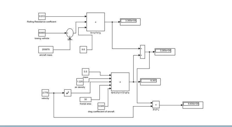
In order to understand the above simulink model .
- For calculating power we have to multiply both total force(F) and velocity in m/sec for this we have used 'product' block (P=F*V).
- For calculating the Total Force(F) we have added both Frr & Fd by using 'Sum' block as shown in the above figure.
- To find the value of rolling resistance (Frr) we used product to multiply the values Crr, Total mass(m) & gravity (g) which are to be entered in the 'Constant' block.
- Similarly for calculating Drag force(Fd) we have to multiply the velocity in m/sec,Drag coefficient, Frontal area of aircraft(A) and a constant value 0.5 which are to be entered in 'constant' block.
- In order to convert velocity in Kmph to m/sec we have multiplied it with 5/18.
7a) Aim :
Force required to push/pull the aircraft =19.508 KN
Power required =135.478 kw
Let us assume,
The Radius of the Tyre for the Tug = 25inches =0.635m
Gear ratio = 8
Transmission Effeciency (ηt) =87%
Motor Efficiency (ηm)=95%
then,
Torque required for the wheels (Tw)=Total Force *Radius in meters
=19.508*0.635
= 12.387KNm
Motor Torque= Wheel torque/(Gear ratio*ηt)
= 12.387 / (8*0.87)
= 1.778KNm
For ηm =95%,
The required motor Torque (Tm)= 1.778/0.95 =1.871 kNm
Similarly, The total power required by the motor considering all the efficiencies(Pt) = 135.478/(0.87*0.95)=163.917Kw
Let us assume the towing operation was done for a 15 minutes (0.25Hrs) duration.
Then, Total Energy consumed = 163.917*0.25 = 40.98 KWh
If we consider the battery capacity =220 kw is used by the towing vehicle then, The duty cycle range to control the speed from 0 to max speed (3m/s) is given as
Duty Cycle (d) = (Required Power)/ (Rated power)= 163.917/220 =0.75
Therefore the controller will be able to provide a duty cycle ranging from 0 to 75% in order to control the towing speed.
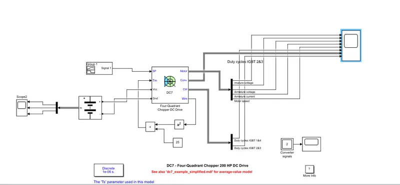
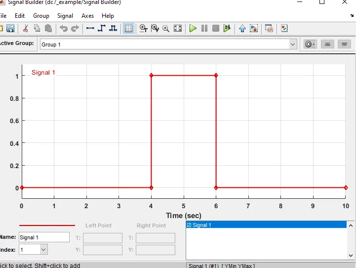
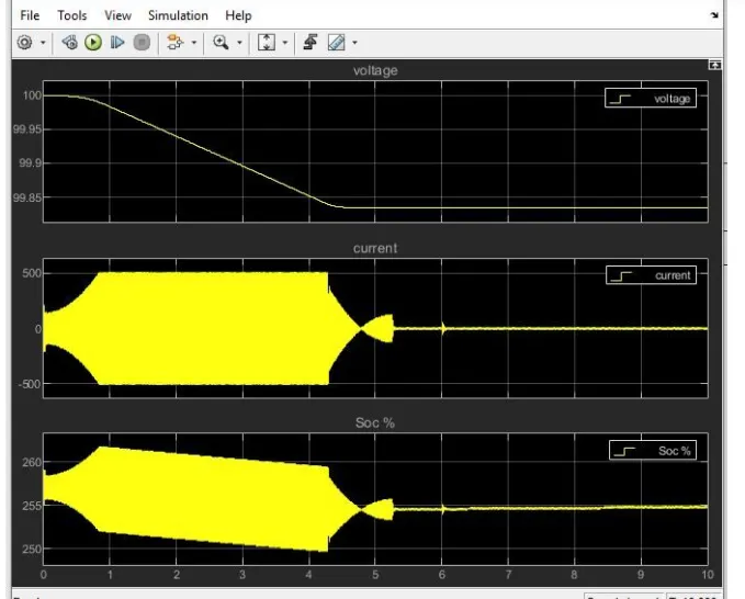
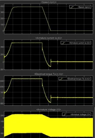
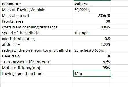
7b) To Design the parameters in excel sheet.