Project - Speed Control of a Direct Current (DC) motor
Aim
A Simulink model for the DC motor by using the Proportional, Integral, and Derivative (PID) control design knowledge gained in the training to design, develop and test a controller to maintain a desired speed for the motor.
Describtion
Simulink model of a dc motor by using PID control design
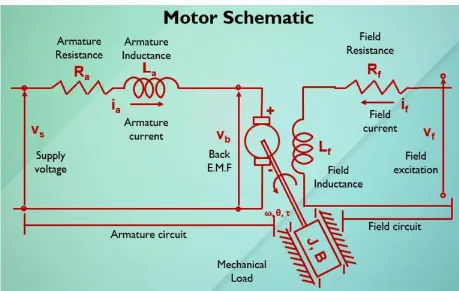
Steady state model :
Armature current =ia
Back emf =vb
voltage source=vs
Armature inductance =La
Armature Resistance=Ra
J=Rotational inertia
B= Viscous friction
T=Motor Torque
w=Motor speed
Tf=Motor friction torque
The equations are
Torque
Torque=Kt.ia-Tf N(m
Kvl(Armature circuit)
Ea=ia.Ra+eb.v
Ea=armature voltage
Eb=back emf
Ra=Armature resistance
Back emf
Eb=Ke.wm.V
Wm=shaft spped(rad/s)
Eb=Back emf
Ke=Back emf constant
Developed Power
P=wm.T W
P=Power shaft
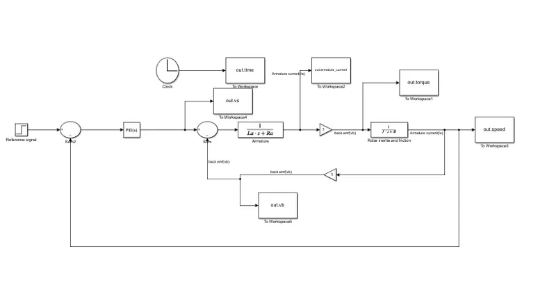
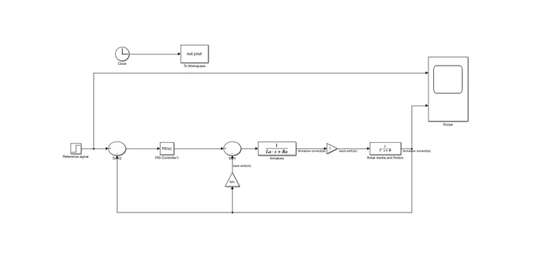
SIMULINK BLOCK DIAGRAM OF DC MOTOR CONTROLLER SPEED
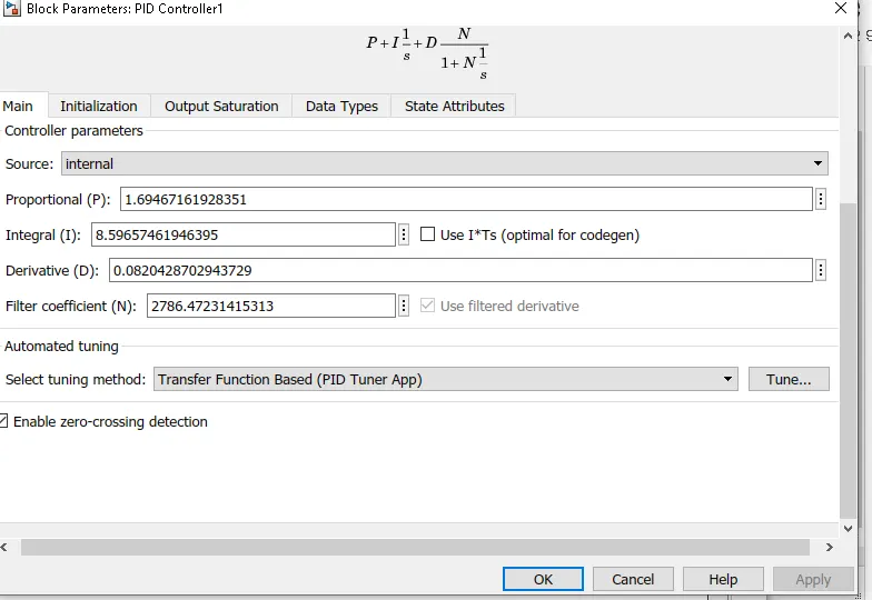
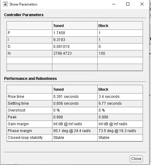
PID controller
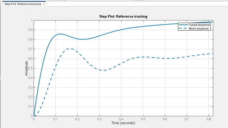
Simulink block diagram of a dc motor output by scope :
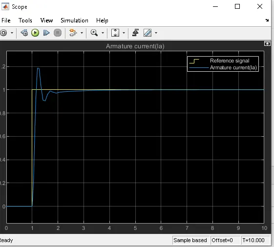
Scope
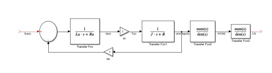
The above Dc motor controlled are shown Armature circuit field circuit with mechanical load
Here the Ea and Eb are the inputs and i(t) is the output
The kvl equation is
Ea(t)=Ra.ia(t) +L.d ia(t)/dt+Eb(t)
Mechanical Dynamics
T(t)=Jm.dwm(t)/dt+Bm.wm(t)
The Electromechanical equations
Eb(t)=Ke.wm(t)
T(t)=Kt.ia(t)
The laplace transform of equation is
Ia(s)=[1/L.s+Ra].Ea(s)-Eb(s)
T(s)=[Jm.s+Bm].ohm sign (s)=ohm sign(s)=[1/Jm.s+Bm].T(s)
The motor shaft position is the integral of the motor velocity with respect to ti,me.To find shaft position,integrate velocity
To find the motor shaft position with respect with respect to armature voltage
Dc motor Transfer function
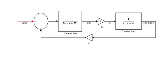
Back emf ,angular velocityand Torque
vb=Km.d(angular velocity)/dt
Torque =Kti
Km and Kt are back emf and torque constants are used.
MOTOR TRANSFER FUNCTION WITH SPEED CHANGER
Final value
The open loop Transform motor with speed (w) and supply volatage Vs
w(s)/vs(s)=KT/JLas^2+(JRa+BLa)s+(B.Ra+KT.Km)
desired angular speed using the applied supply voltage.