Project 1
Problem 1 :
Aim : Design a battery pack for a car roughly 150 Kw with 120 V. Use 3500 mAh 3.6V nominal NMC chemistry cell.
a. Design the battery pack configuration.
b. Draw the BMS topology for this battery pack
Battery pack configurations
Battery pack configurations can be designed with several options, some of which are determined by the chemistry, cell type, desired voltage and capacity, and dimensional space constraints.
The basic explanation is how the battery cells are physically connected in series and parallel to achieve the desired power of the pack.
Given that
Battery power = 150kw
Voltage = 120V
Battery Capacity = 3500mAh
Nominal Voltage = 3.6V
No.of cells Connected in series
As Per the Battery connected in series = Required Voltage / Nominal Voltage
The cell connected in series = 120/3.6 =33.33cells
Therefore the connected in series =34
No.of cells connected in parallel
No.of cells connected in parallel =Reading continuous current / cell nominal
Required power=150Kw
Required Voltage= 120V
NMC Battery details
Batatry capacity = 3500 mAh= 3.5 Ah
Battery Nominal Voltage =3.6V
We know that ,
Power(P) = Current(I) * Voltage(V)I=P/V
hence, From formula,
Current(I) = power(P) / Voltage(V)
= (150000) / 120
Current(I) = 1250 Amps
from the data ,
Current(I) = 1250 Amps
Cell nominal Voltage = 3.6 V
then ,
`"Number of cells Connected in parallel" = "Required Current (I) "/ "Cell Nominal Voltage(V)"`
=1250 / 3.6
=358
There fore The No.of cells connected in parallel=358
Hence,here define dthe parallel and series cells
The connected series cells=34
The connected series parallel =358
b Draw the BMS topology for this battery pack.
BMS Topology:-
Basically BMS topology is classified into following foure(4) types:-
1)Centralised Topology;-
This Topology is used for only pack of 18 cells or less than 18 cells in a series only.It has small energy storage used in two wheelers or three wheelers.
2)Master and Slave topology:-
This Topology is used for pack of 18 cells or grater than 18 cells in a series ,generally used in 4 wheelers
High Energy storage purpose
3)Modular Topology :-
This Topology is used for pack of 18 cells or grater than 18 cells in a series .
Very Large Energy storage battery pack system
eg 1MW battery pack system
4)Distributed Topology:-
This Topology is used for pack of 18 cells or grater than 18 cells in a series .
Very large Large Energy storage purpose
Individual cell consist of a pack voltage sensor
Generally used in small energy storage battery pack system,its easy to implement,but cost is very high.
Solution:-
From the Architecture of BMS we can said that the "AFU" Allowes ony 18 cells connected in series per one unit of modulae.
Hence ,
we required series cells is 34 cells
There fore we are dividing these 34 celss as 2 slave sets with 1 number of MCU master unit as followes
Slave 1= 17 cells
Slave 2= 17 cells
Based on this cells connected in series and Architecture of BMS we Choose the Master and Slave topology of BMS for this Ev battery pack Topology design.
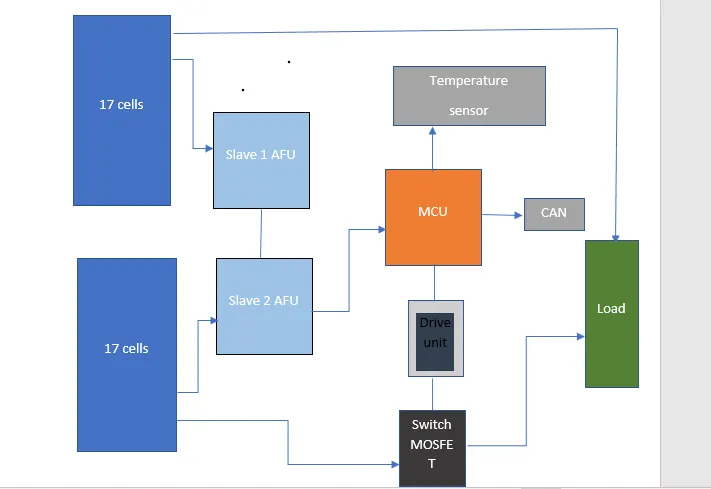
Above Model is For BMS Topology of 34s358P battery pack Configaration model This Topology consists a 2 numbers of slave of AFU units with each AFU units slave Consists a 17 numbers Of Cells connectd in series.
Problem 2: To Build a 3S2P battery pack configuration with generic battery block using Matlab/Simulink.
The battery block with its charging capacity
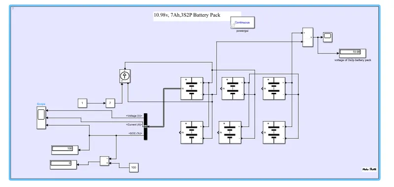
The voltage measurement block is connected across the battery pack to measure the battery pack voltage,when it is charging and discharging .
The scope output used for the battery pack consists of SOC (State of Charge), Current and voltage. The controlled current signal is given as the load to the battery pack. The constant blockis determined with battery capacity and it is given to the controlled current block.
The parameter given inside the battery is given below:-
- Nominal voltage of a cell 3.7V
- Rated capacity of a cell 3.5Ah
- Maximum voltage of a cell 4.3068V
There fore ,
Nominal voltage of the battery pack = no.of cell in series * nominal voltage of a cell
= 3 * 3.7v= 11.1V
Rated capacity of the battery pack = no.of cell in parallel* rated capacity of a cell
= 2 * 3.4Ah= 6.8Ah
-
The model is for an 10.98V 7Ah with 3s2p battery capacity
Overall voltage of the battery pack = maximum voltage of the battery * no. of cells in series
= 4.3068V * 3= 12.9 v
- For discharging voltage=12.9v(discharge)
- For charging voltage =11.1(charging)
The output of the scope says that the charging capacity of the voltage is 11.1v in 3S2P battery pack
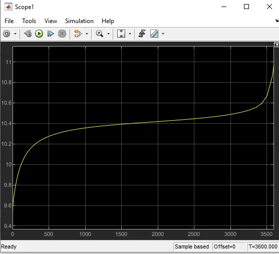
The output of the voltage ,current and state of charge while charging the battery pack
The voltage gets shows its max voltage capacity(fully charged
The current is constant in the series connection
Then the State of charge is gradually is increases from 0 to 100% for 1hr in 3S2P battery pack

The battery block with its discharging capacity 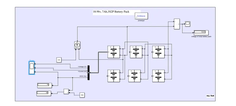
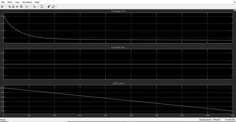
The output of the discharging the battery pack is
The voltage gets decreased capacity( discharged )from 4.3 to 3.7
The current is constant
Then the State of charge is gradually decreases from 100% to 75% for 1/2hr in 3S2P battery pack
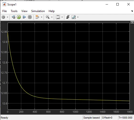
The voltage gets decreasing starts from 12.95 to 12.62v
Conculsion for above given questions are
I have concluded the battery pack configuration for the given data for nominal cell as showing its parallel and series connection cells.
I have concluded the BMS topology for its cells by using the master and slave topology for Battery management sysyem.
I have concluded the simulink model for the 3S2P battery pack with its charging and discharging capacity with its battery parameters.