gyroscope toy simulation
Gyroscope toy simulation
introduction: this assignment is about making a simulation of a toy in multi body dynamics using solid works and studying the phenomenon of gyroscopic effect and how it's affected by various external parameters. This assignment involves part modelling, assembly followed by the setup and simulation of the gyroscope toy. There are two types of test being carried out on the gyroscope in the below assignment and the result are compared and verified with the analytical equations.
Objective:
To simulate a working of a gyroscope toy and understand the mechanics behind it. To know how gyroscopic effect is used in different engineering application such a flight ,helicopter.
Motive:
The first time i saw toy of a gyroscope i wanted to buy it then i read about it , it was hard to wrap my mind to this concept. But after reading and watching examples of the gyroscopic effect now i can understand it in a better way. Then i wanted to understand it in a better way not in terms of equation but something practical as the labs are closed i used the solid works tool a make a model of the toy and used mbd to make the simulation.
Steps involved:
Design: i designed the model of the rotor , shaft and the holder separately ,similar to the toy which i wanted to buy (similar to a toy dimension)
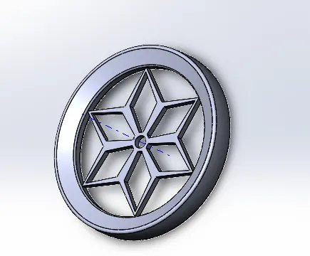
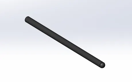
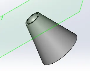
Assembly: the i assembled the shaft with the holder @60degree with the ground and mounting the rotor at the in the shaft .
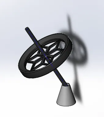
Mbd setup
contact points:between the shaft and the rotor, shaft and the holder
Motor: to the axis of the rotor
Results : choose the required quantities to measure and their axis.
Test -1 (different rotor speed)
So, after the assembly is done i made the rotor to rotate a different speeds and studies how the gyroscopic toy is behaving .(same material is used )
Analysing the different measurements quantities and trajectories of the shaft.
Learn how to measure the different quantities and their axis
Response of the toy model is compared with the analytical motion equation.
Test-2 (different loads on same speed )
Now the material of the rotor and shaft are changed thus altering the disturbing torque due to the gravitational force acting on the shaft and rotor .
Buy this we can study how the disturbing torque affect the motion of the gyroscope
results
result-1:
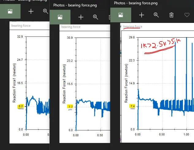
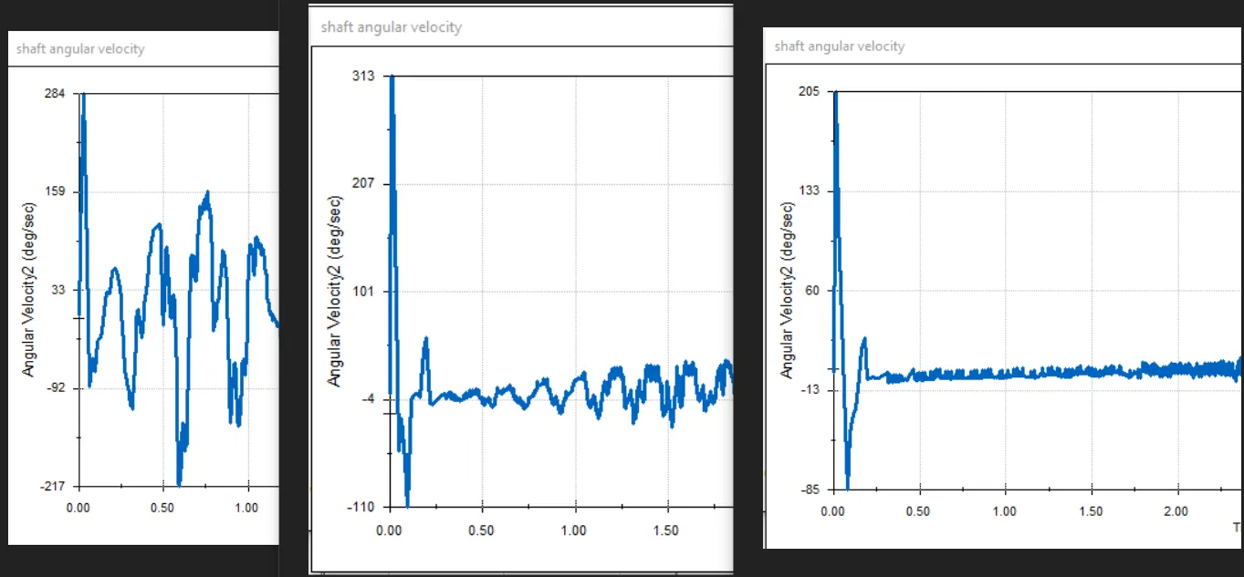
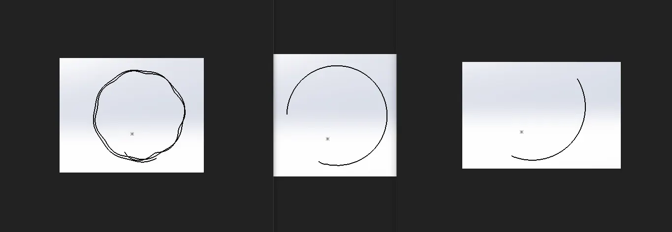
Bearing force as the rotor tend to rotate faster the reduces but the total weight of the material remains the same .
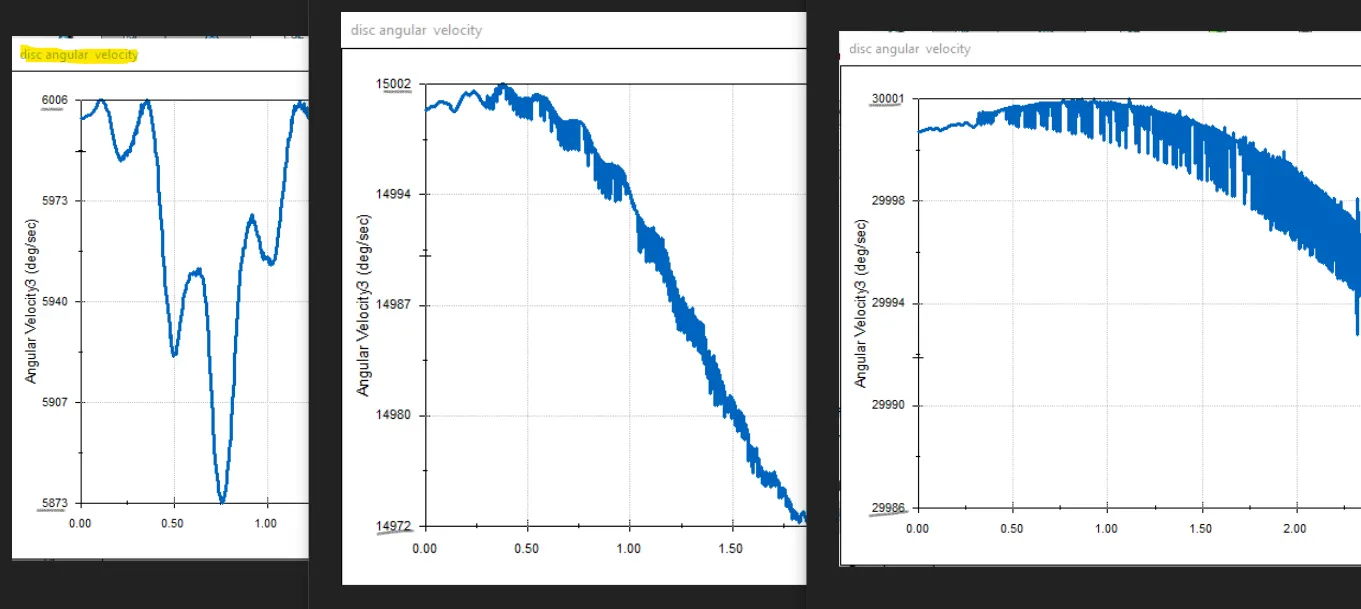
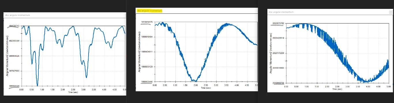
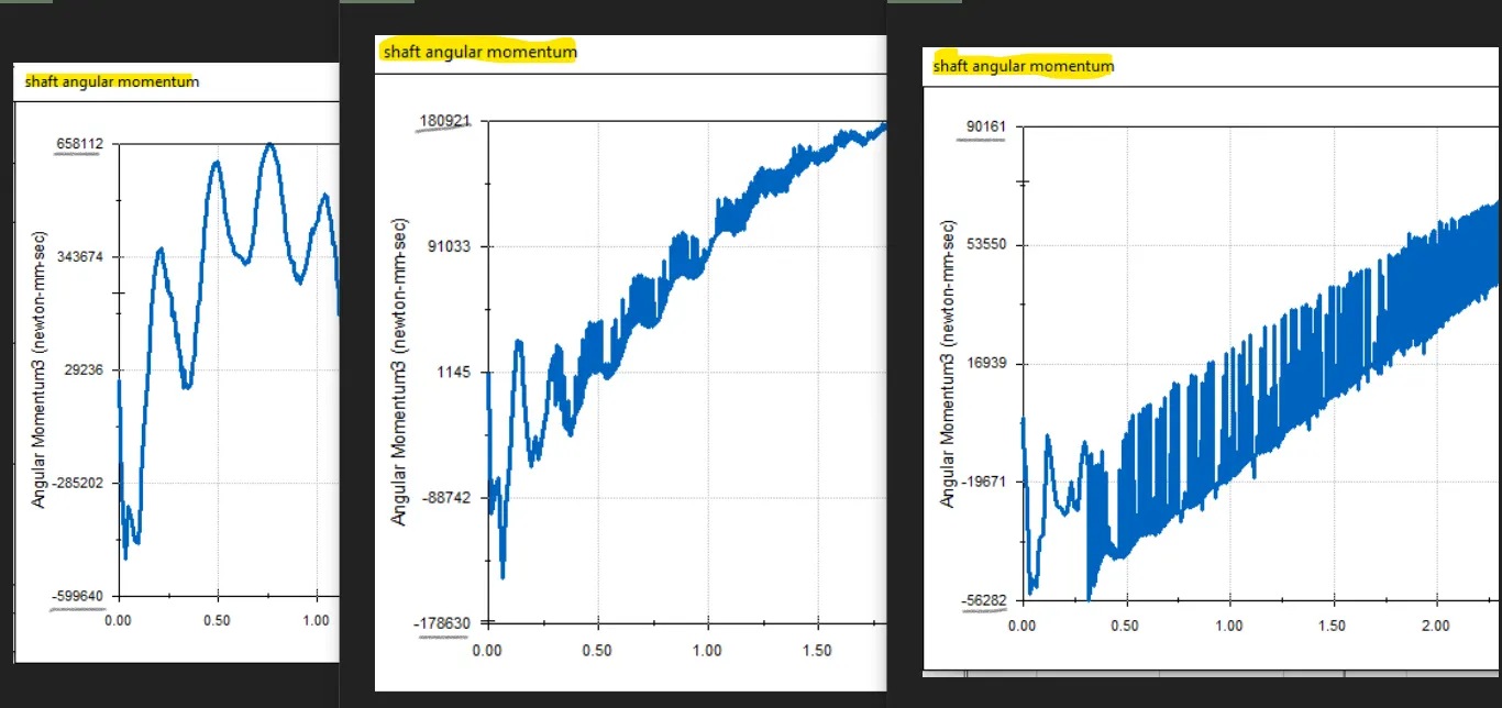
Angular velocity and momentum. The fluctuation in the values reduces as the rotor speed increases the shaft becomes more rigid and less vibration.
The gyroscopic precision or angular velocity of the shaft reduces as the rotor speed increases this can compared to the trace path of the shaft for 5sec.
wp=(m*g*l/I*w) using this analytical equation the phenomenon can be better understood.
result-2:
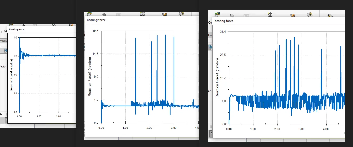
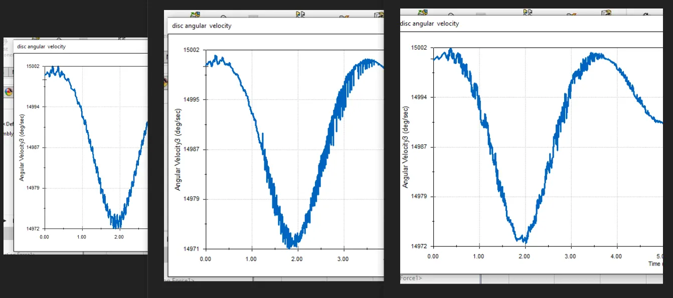
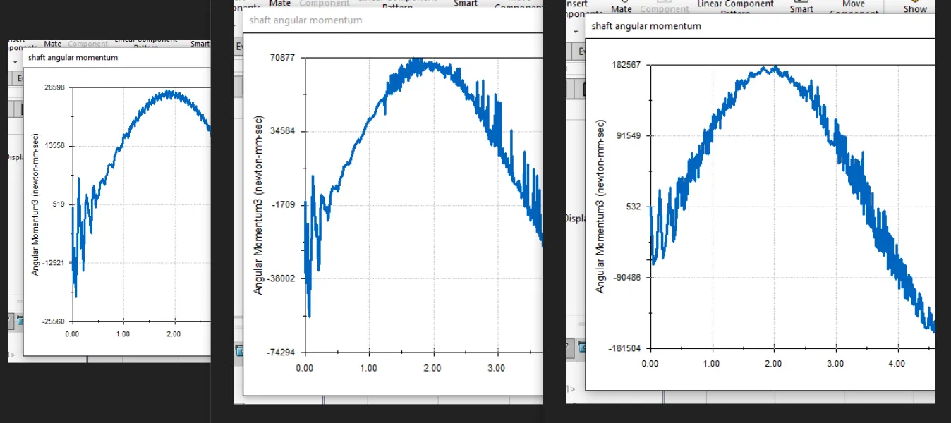
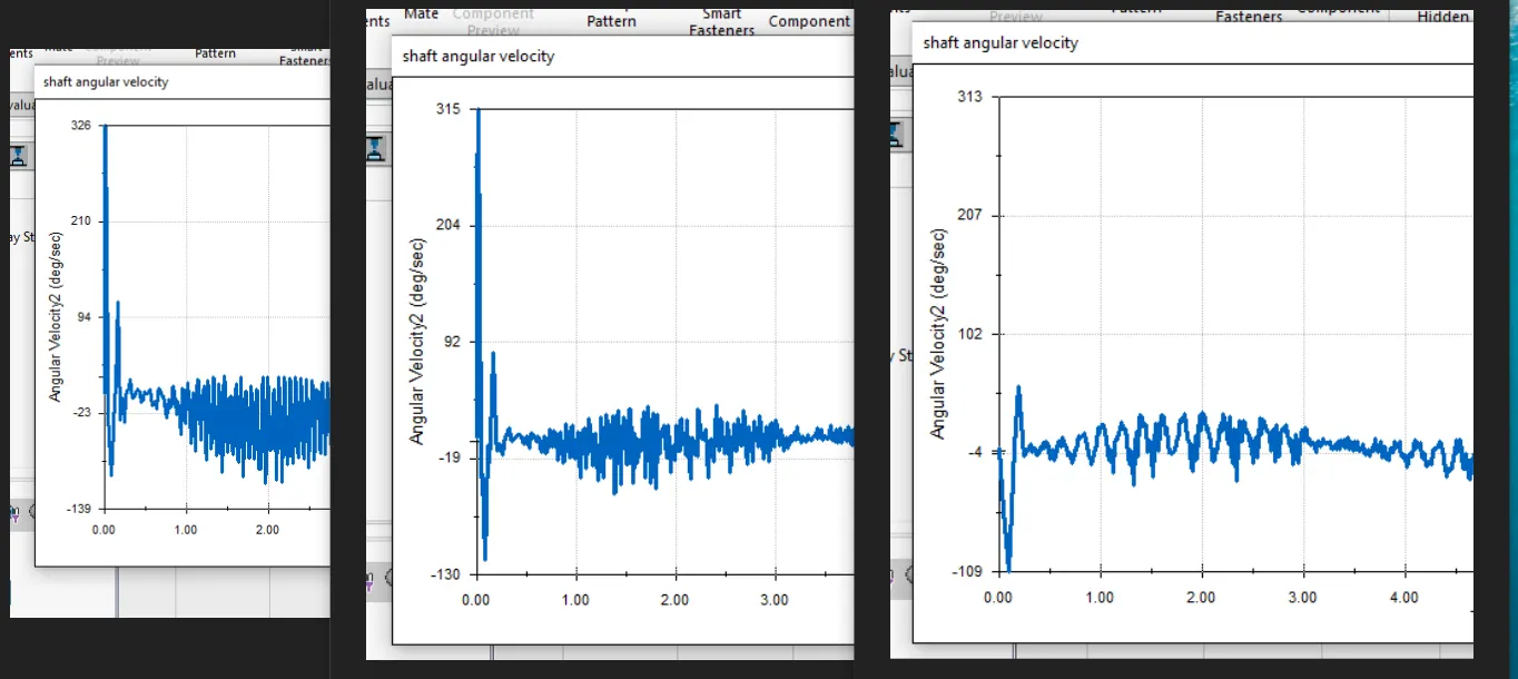
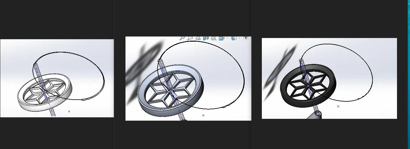
The reaction due to change of material of the shaft and the rotor
Plastic ,aluminium, cast iron. These are the materials used .
Bearing force : as the weight of the material increases the bearing force also increases
Disc velocity and moment : the vibration increases due to the increase in the inertial force .
Shaft velocity and moment : the vibration in reduces in inverse to the disc as the disc mass increases.
Gyroscopic precess stays the same.