centrifugal pump
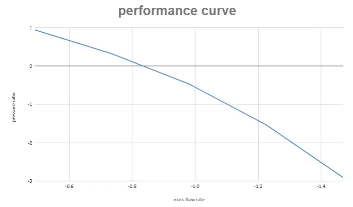
AIM: to Obtain the relationship between Pressure ratio and mass flow rate and explain the results
Pressure ratio = Outlet total pressure/Inlet total pressure
INTRODUCTION:
This assignment is about studying the performance curve of the pump driven at a constant rpm. There won't be much of pressure loss in an efficiently designed motor.we set up flow simulation to understand the behavior of the centrifugal pump we designed.
Explanation:
>first we create the model of the centrifugal pump we start off by making propeller in 2d and extrude it
>then we create the casing for pump ,attach the inlet and out let pipe to it using extrude ,before extruding the casing make sure you uncheck the merge geometry .make use of the shell command to make it hallow shell,before that merge the inlet outlet with the casing(using combine option)
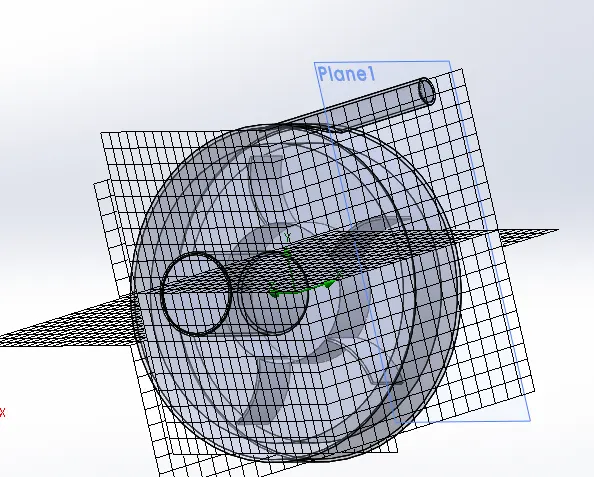
>rotating volume boundry is created such that it encapsules the propeller but dose not intersect with the casing
>flow simulation wizard physical parameter rotation is checked ,internal flow ,units, types of working fluid as well
>setting up mesh-the mesh is generated using the automatic mesh creation(size-3) ,then i added advanced refinement mesh check list to make sure that results are accurate.
>set up the input and output boundry layer condition.(inlet-total ambient pressure ,oulet-velocity)
>then set up the goals for meausing pressure (suface goals-mass flow,presure at outlet )
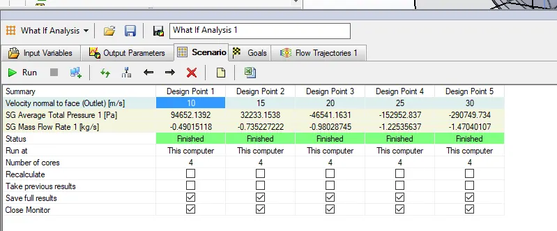
>now create a parametric study for different oulet velocities and messure the corresponding pressure fluctuations in the outlet.
>the calculation parameters are set to 200 iterations so that the result dosent converges quickly ensuring a better results .
results:
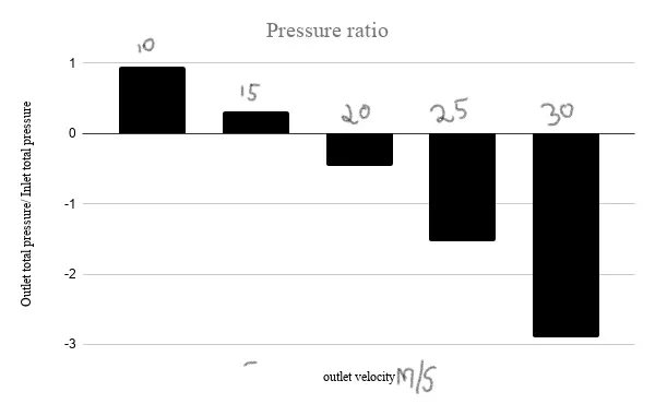
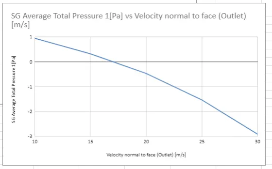
The ratio of the pressure reduces steadily as the velocity increases.
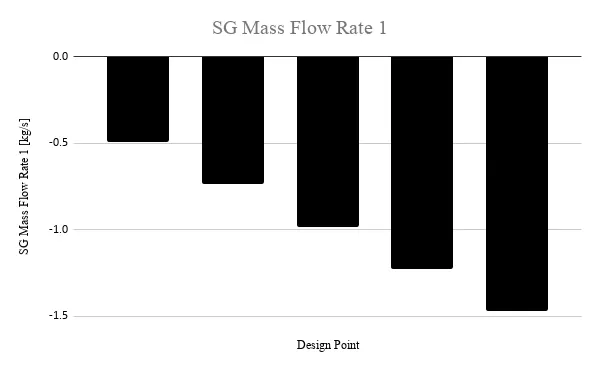
Mass flow rate increases proportional to the outlet velocity
pressure ratio vs velocity:
pressure ratio vs mass flow rate
mesh and model:
parametric study result table:
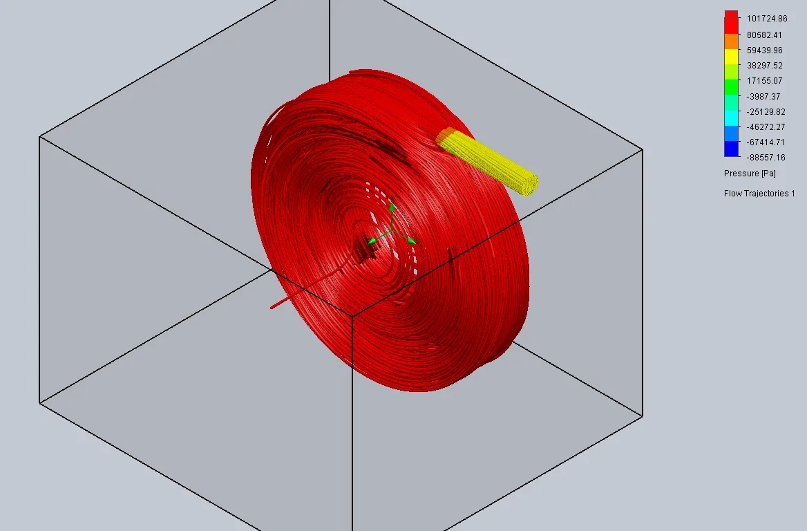
flow trajectories:
10m/s 15m/s 20m/s
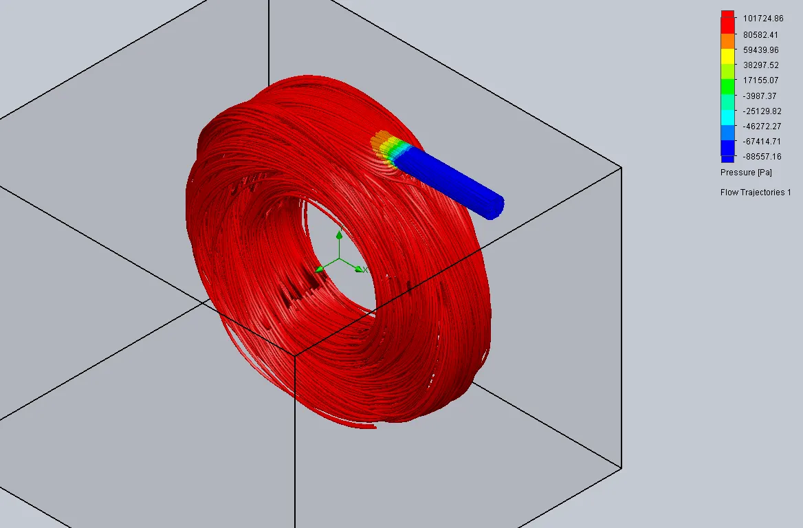
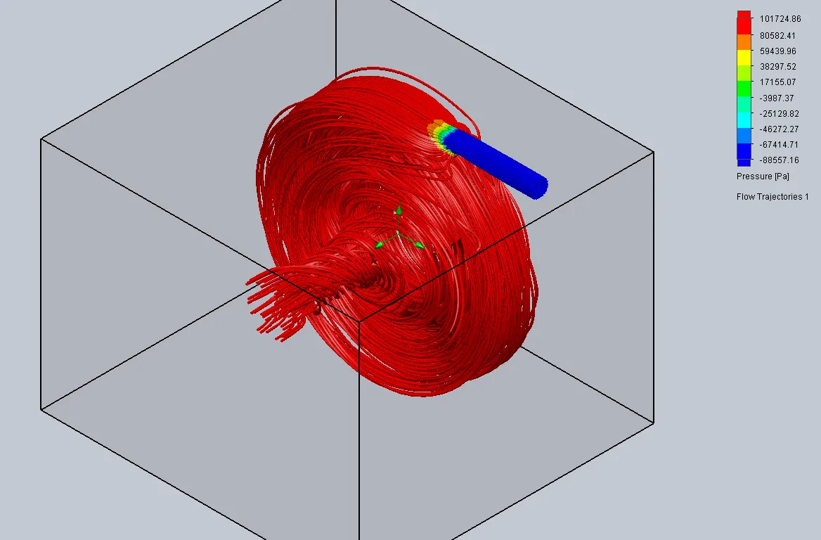
25m/s 30m/s
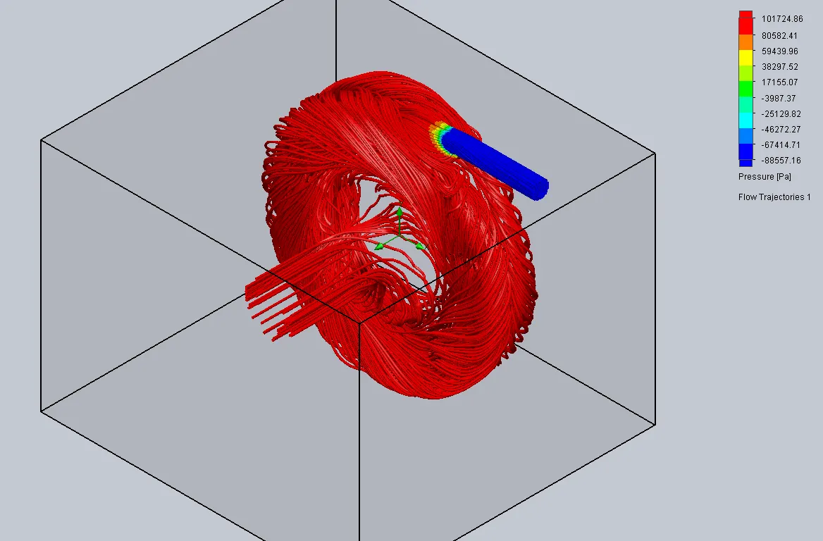
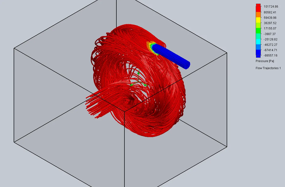
The blue represents the region of low pressure at the outlet .
Animation:
the animation of the floe trajectories shows that how the fluid flow inside the pump
it is sucked by the vacuum created inside the pump by the impeller a directed to flow outwards imparting energy in the fluid
conclusion :
the effects of the pump is been studied successfully and the result are been analyzed