Determining the damping force vs Velocity curve of a corner mass of a vehicle
https://drive.google.com/file/d/1aX1pZMvvYGigJV2dYjFepRHc6lyjZ60o/view?usp=sharing
Data Available :
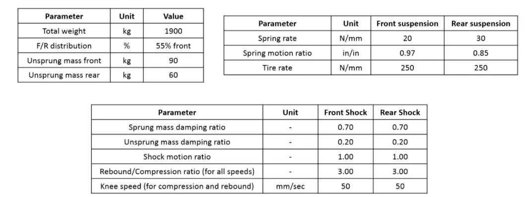
Aim : To calculate the damping force vs Velocity curve of a corner mass of a vehicle
Software used :
- Excel for preliminary calculations
- Octave for creating the force vs velocity curve
Flow of the calculation :
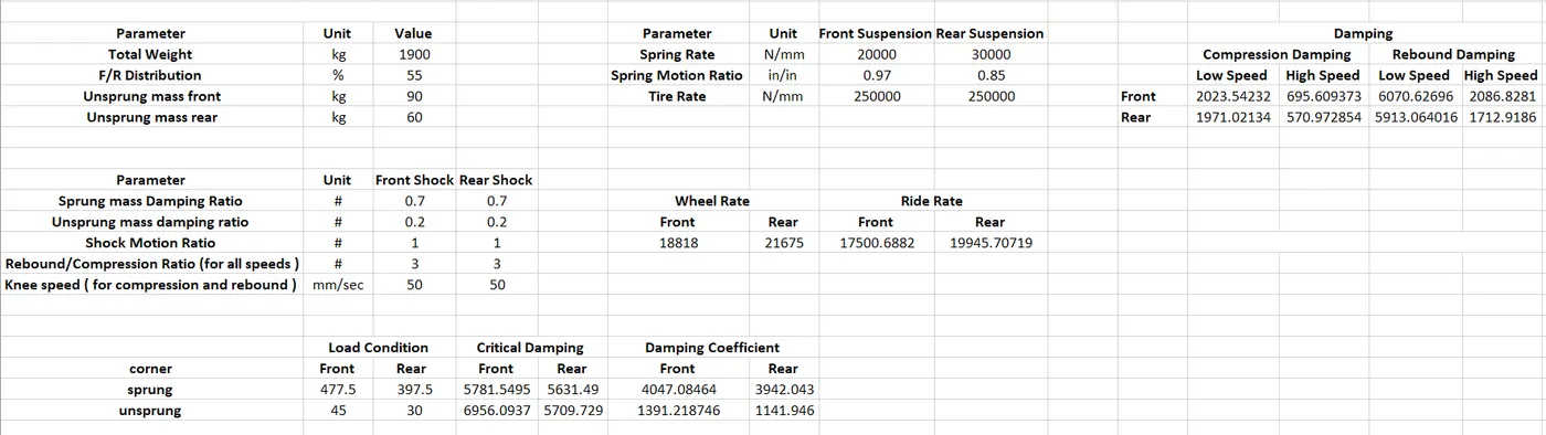
- Ride rate , Wheel Rate
- Load Condition ( corner mass ; Sprung-Unsprung )
- Critical Damping
- Damping Coefficient
- Damping ( Compression-Rebound )
Formula used :
- Wheel Rate = Spring Rate * (MR)^2
- Ride rate = (Wheel rate*Tire Rate )/(Wheel rate+Tire Rate )
- Corner sprung mass(Front)= ((Total mass*FR ratio )-front axle unsprung mass)/2
- Critical Damping (Sprung mass ) = 2*sqrt( Ride rate * Corner sprung mass )
- Critical Damping ( Unsprung mass ) = 2*sqrt((wheel rate + Ride rate )*Corner Sprung Mass )
- Sprung mass initial damping coefficient = Sprung mass Damping Ratio* Sprung mass Critical Damping
- Unsprung mass initial damping coeffcient = Unsprung mass Damping ratio * Unsprung mass Critical Damping
- High Speed Compression Damping Coefficient = Unsprung mass initial damping coeffcient/2
- Low Speed Compression Damping Coefficient = Sprung mass initial damping coeffcient/2
- High Speed Rebound Damping Coefficient = Rebound/Compression Ratio * High Speed Compression Damping Coefficient
- Low Speed Rebound Damping Coeffcient = Rebound/Compression Ratio * Low Speed Compression Damping Coefficient
- Force Calculation
Below Knee Speed (<=50mm/sec)
- Compression Force = Low Speed Compression Damping Coefficient * Velocity
- Rebound Force = - Low Speed Rebound Damping Coefficient* Velocity
Above Knee Speed
- Compression Force = Compression Force(n-1) +[Velocity(n) -Velocity(n-1)]*High Speed Compression Damping Coefficient
- Rebound Force = Rebound Force(n-1) - [Velocity(n) -Velocity(n-1)]*High Speed Rebound Damping Coefficient
Theory
- Compression damping is lower than rebound damping by factor of 2 or 3 because during compression spring absorbs half of the energy , so not much damping force is needed force but when the reboud happens the springs releases the energy so the damper now has to control the spring energy and also control & damp the unsprung mass .
- There are 4 different curves in a Force velocity graph to account for the Sprung masses ( low velocity ) , Unsprung masses ( high velocity ) .
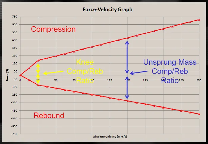
- In circuit racing the shaft velocity between 0-50 mm/s are considered low speeds and contribute to driver feel and car body's movements ( sprung mass ) .Speeds betwen 50-150 are called mid range velocities and these affect the braking and or sharp turns . Above 150 mm/s are high speed shaft velocities and they absorb the energy form bumps and control the energy from unsprung mass .
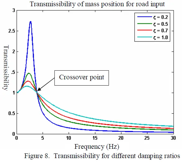
- We chose high damping ratio ( high damping ) for when we are at the low frequency this will reduce the transmissibility and low damping ratio for ( low damping ) for high frequencies to also reduce the transmissibilty .
Concept used to create the code :
- For loop
- Basic Graph Commands
- Concept of Dynamic Array Initialisation
clear all
close all
clc
#Force_vs_velocity_curve
cdamp_low_front=2023.54232 # N/m/sec
cdamp_low_rear=1971.021339 # N/m/sec
cdamp_high_front=695.6093731 # N/m/sec
cdamp_high_rear=570.972854 # N/m/sec
rdamp_low_front=6070.62696 # N/m/sec
rdamp_low_rear= 5913.064016 # N/m/sec
rdamp_high_front=2086.828119 # N/m/sec
rdamp_high_rear=1712.918562 # N/m/sec
vel=(0:5:500);
t=1;

for i=1:101

  if i==1
    cforce_front(t)=0;
    cforce_rear(t)=0;
    rforce_front(t)=0;
    rforce_rear(t)=0;

     elseif i<=10
      cforce_front(t) = cdamp_low_front*vel(i) ;
      rforce_front(t) = -rdamp_low_front*vel(i) ;
      cforce_rear(t) = cdamp_low_rear*vel(i);
      rforce_rear(t) = -rdamp_low_rear*vel(i);

     else i>10
      cforce_front(t) =cforce_front(t-1)+(vel(i)-vel(i-1))*cdamp_high_front;
      rforce_front(t) =rforce_front(t-1)-(vel(i)-vel(i-1))*rdamp_high_front;
      cforce_rear(t) =cforce_rear(t-1)+(vel(i)-vel(i-1))*cdamp_high_rear;
      rforce_rear(t) = rforce_rear(t-1)-(vel(i)-vel(i-1))*rdamp_high_rear;
    end
    t+=1;
end

figure(1);
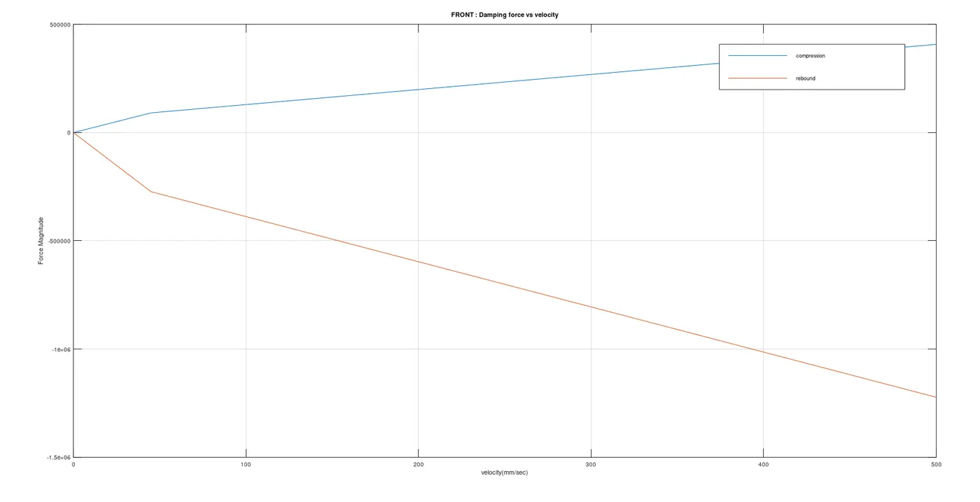
plot(vel,cforce_front);
hold on
plot(vel,rforce_front);
hold off
box on
grid on

title('FRONT : Damping force vs velocity');
xlabel('velocity(mm/sec)');
ylabel('Force Magnitude');
legend('compression','rebound');

figure(2);
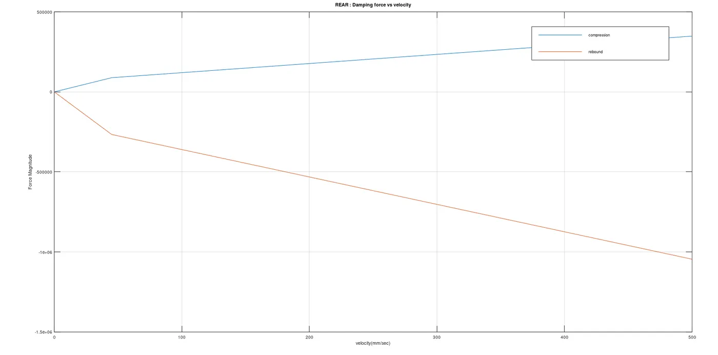
plot(vel,cforce_rear);
hold on
plot(vel,rforce_rear);
hold off
box on
grid on

title('REAR : Damping force vs velocity');
xlabel('velocity(mm/sec)');
ylabel('Force Magnitude');
legend('compression','rebound');
Observation & Conclusion
- As you can see the slope of rebound is twice/thrice larger than the compression curve in both the front and rear cases . And both the graphs are quite similar which shows there is no irregularity in the damping forces experienced by the corner masses .
- Prajwal Gcan you share the drive link once again please because the link is not working