Bird Strike - Project - 2
Project-2 Bird Strike
OBJECTIVE:
To simulate a bird strike on an Aero Engine in an organized and disciplined manner with a consistent numbering approach and also to use mass scaling technique to reduce the run time of the model.
PROCEDURE:
- The meshed model of bird strike.key file is imported into Ls-prepost and exported as seperate .key files for Blade, Hub, Casing, Bird.
- A seperate .key file is created for Control cards and boundary conditions. A main file is also created whcih contains only the reference path of the seperate FE files for the analysis.
- *Include Keyword is used to call all the seperate .key file to the main file in such a way that the project folder can be copied anywhere and the simulation will run correctly.
- Now the main file is loaded into Ls-prepsot.
- A consistent Numbering approach is followed for this simulation
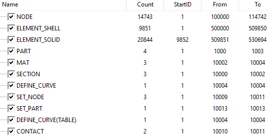
- All the nodes are renumbered from 100000, all the elements are renumbered from 500000, all the Parts are renumbered from 1000 to 1003
- All other keywords are renumbered from 10000. It is ensured that no duplicate IDs exist.
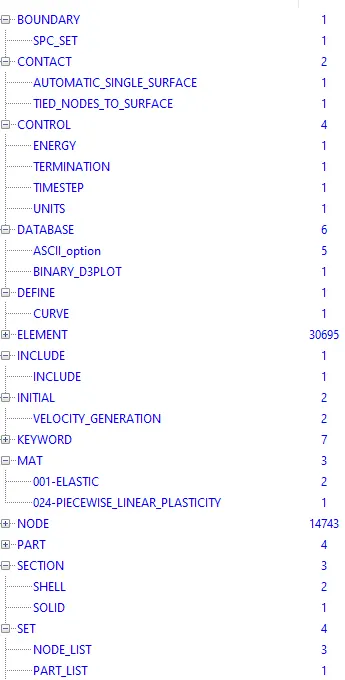
- Section is defined as solid for the Hub part and shell for all other parts (Bird, casing and blades). For bird, 1mm thickness is defined and for casing and blade, 3mm thickness is defined.
- For solid section, ELFORM is defined with the value 4 and for shell section, ELFORM 16 (fully inetegrated elements) is defined.
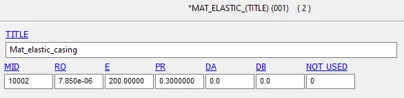
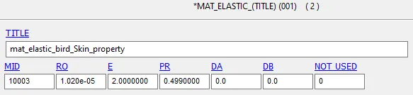
- In Material keyword, MAT001_Elastic material is defined for Bird and casing. The material parameters are as follows. The unit system followed here is Kg mm ms
- BIRD
Density=1.02e-05 Kg/cubic millimeter
Youngs Modulus=2 Gpa
Poisson Ratio=0.499
- CASING
Density=7.85e-06 Kg/cubic millimeter
Youngs Modulus=200 Gpa
Poisson Ratio=0.3
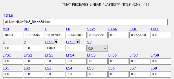
- MAT024_Piecewise_linear_plasticity was already given in the model. This card is called to the main file using *include keyword. This material is defined for Blade and Hub parts. The material used is Aluminum 994
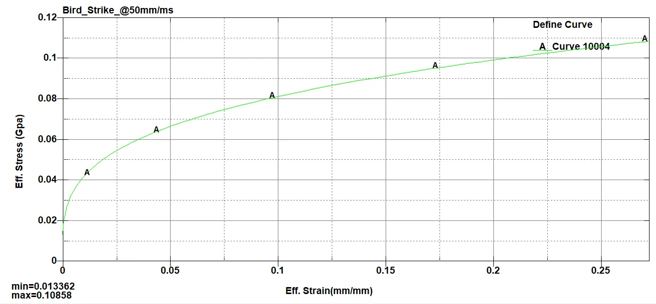
- A Load curve ID defining effective stress versus effective plastic strain is also added to the material card.
- The material parameters are as follows:
Density=2.713e-06 Kg/cubic millimeter
Youngs Modulus=68.947 Gpa
Poisson Ratio=0.33
Yield stress=0.01336
- All the Parts are assigned with the appropriate section and material card.
- SPC is defined with casing by arresting it in all the global directions. This is done to make the simulation stable and to avoid movement of the casing.
- Tied_Node_to_surface contact is defined between the blade and hub where the hub is defined as the master and the blades as slave as the moving parts are defiend as slaves. This is done to attach the blades to the hub by it common nodes.
- Atomatic_single_surface contact is also defined in the model where Blade and Bird are considered as slave.This is done by creating a single part set for both the bird and the blade.
- In the initial keyword, two Velocity generation keyword is created.
- In one keyword, a velocity of 50 mm/ms is given to the bird. This is done by creating a node set for the bird and assigning it in the velocity generation keyword. It is created in such a way that the bird will travel in its own axis(X axis).
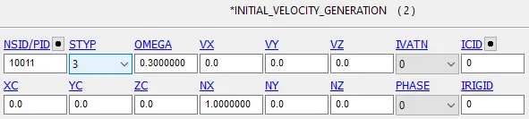
- In the other keyword, an omega value of 0.3 rad/ms is given (approx 9000rpm). This is defined for the rotational velocity for the blades.This is done by creating a node set for the blade part and assigning it in the velocity generation keyword. Direction cosine is also defined as 1 in NX parameter.
- In control termination keyword, a termination time of 3ms is defined.
- In database Binary_D3plot, 0.1 value is given as DT.
- Database ASCII is also defined and all the necessary parameters are opted in with 0.1 as DT.
- Hourglass is also added to the model to make it more stable.
- Now the model is checked with the model checking and no errors or warnings were found.
- The Deck is saved and is ran in Ls-Dyna manager.
- It's been found that the simultion was running perfectly but the estimated clock time for the model was approximately 52 minutes.
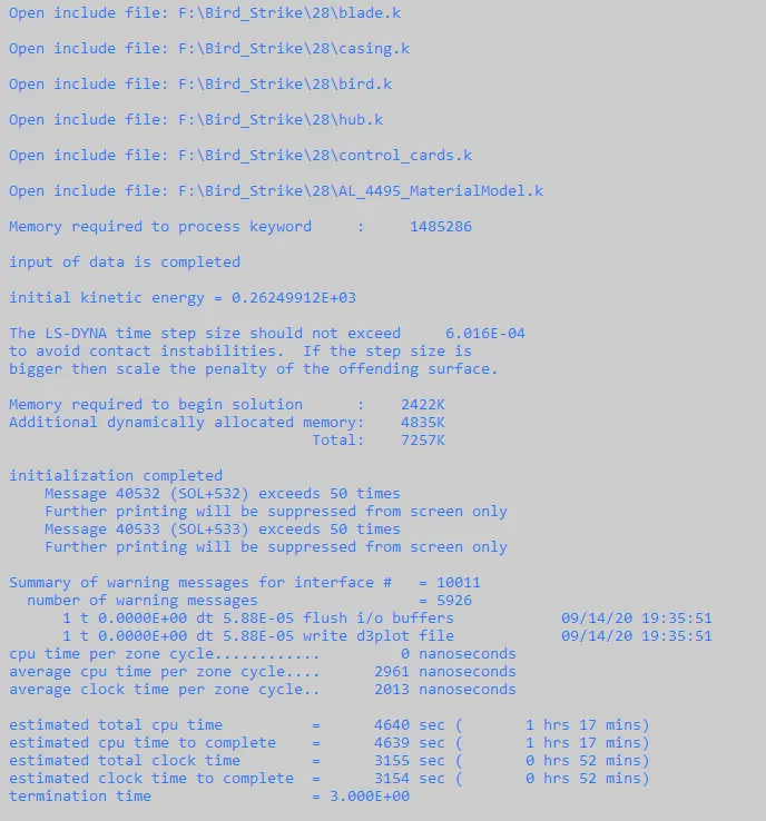
- A timestep card is added to the model for the Mass Scaling.
- Mass scaling is used to reduce the run time of the model by ensuring the stability. For that the mass percent added is kept below 10% of the total mass.
- without mass scaling:
Est. clock time:52 mins
Dt=5.88e-05
Termination Time=3ms
No. of time step required=Terminiation time/ Dt
=3/5.88e-05
=5.102e4
Trail 1.
- The parameters changed in the timestep card are as below:
Dt2ms=-4.00e-05
TSSFAC=0.9
- Now the simulation is ran again and the values are checked
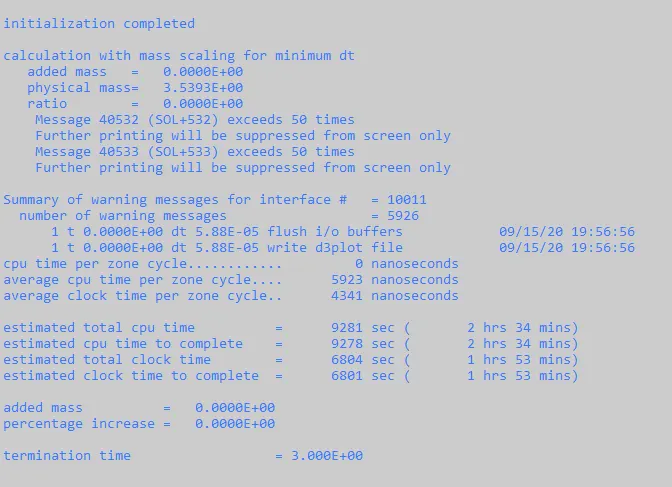
- Sice the Dt2ms value is reduced, the clcok time increased.
- New Estimated clock time is 1hr 53 mins.
- Here selective mass scaling (SMS) is used.Using this method, only the high frequencies are affected, whereas the low frequencies (rigid body modes) are not influenced. Thereby, a lot of artificial mass can be added to the system without adulterate the global solution. This method is very effective, if it is applied to limited regions with very small critical timesteps.
Trail 2
- The parameters changed in the timestep card are as below:
Dt2ms=-4.00e-05
TSSFAC=0.8
- Now the simulation is ran again and the values are checked.
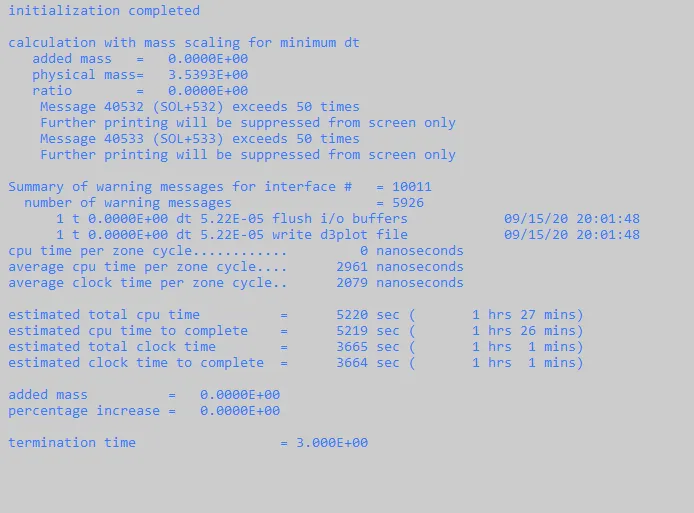
- Since only TSSFAC is changed, zero mass is added to the system. The new estimated clock time obtained is 1 hr 1 min.
Trail 3
- The parameters changed in the timestep card are as below:
Dt2ms=-6.00e-05
TSSFAC=0.9
- Now the simulation is ran again and the values are checked.
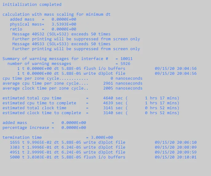
- Here is it seen that mass percent is still zero. that is because the Dt2ms value is still low.
- The new estimated clcok time is 52 mins.
Trail 4
- The parameters changed in the timestep card are as below:
Dt2ms=-6.00e-04
TSSFAC=0.9
- Now the simulation is ran again and the values are checked.
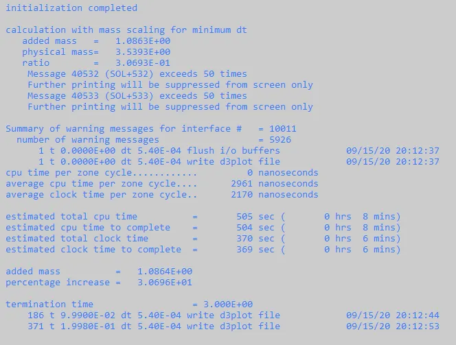
- Now the estimated clock time reduced to 6 mins but the mass percent increase is 30 which is too high. it's always suggested to keep the mass percent increase within 10 percent of the total mass.
Trail 5
- The parameters changed in the timestep card are as below:
Dt2ms=-8.00e-05
TSSFAC=0.9
- Now the simulation is ran again and the values are checked.
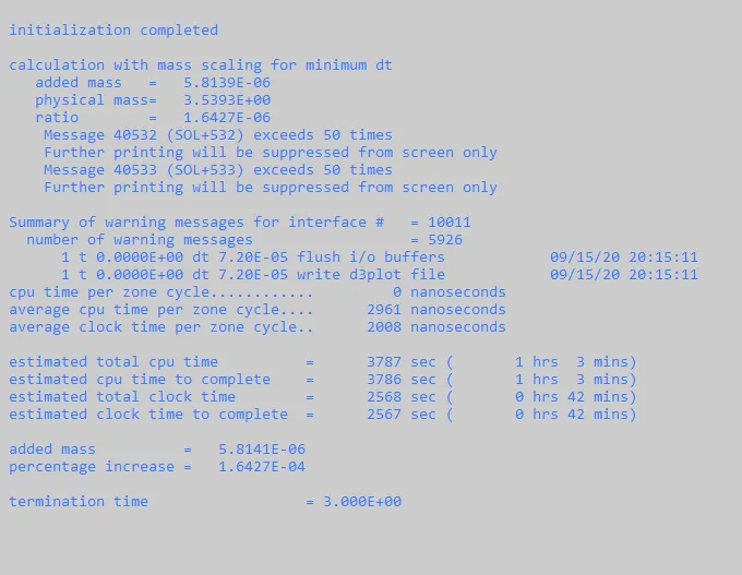
- Now it is seen that the estmiated time went high again and there is only a small increase in mass.
Trail 6
- Further adjustements are done in dt2ms value.
- The parameters changed in the timestep card are as below:
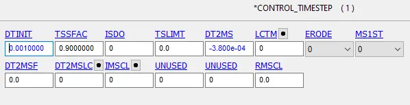
Dt2ms=-3.80e-04
TSSFAC=0.9
- Now the simulation is ran again and the values are checked.
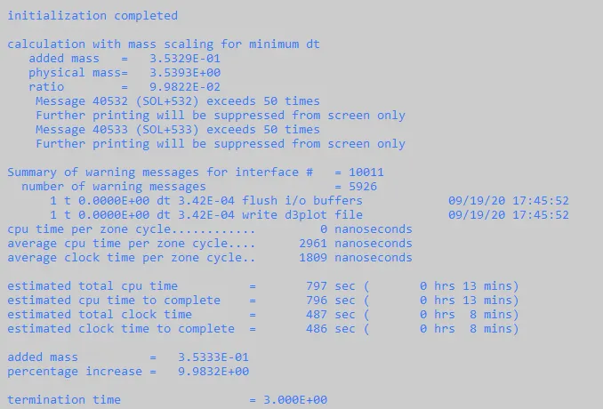
- Now it is seen that the clocktime is reduced to 8 mins within the safe mass percent increase.
- Since the values perfectly changed, no further adjustments are made.
- The final values are:
- Dt2ms=-3.80e-04
- TSSFAC=0.9
- Estimated clock time= 8 mins
- Mass percent increase=9.98%
- Now the model is ran again and D3plot is checked.
RESULTS:
SIMULATION RESULT

- The above Gif file shows the simulation of the bird strike. Blade deformation can be seen within the short span of time.
ENERGY PLOTS
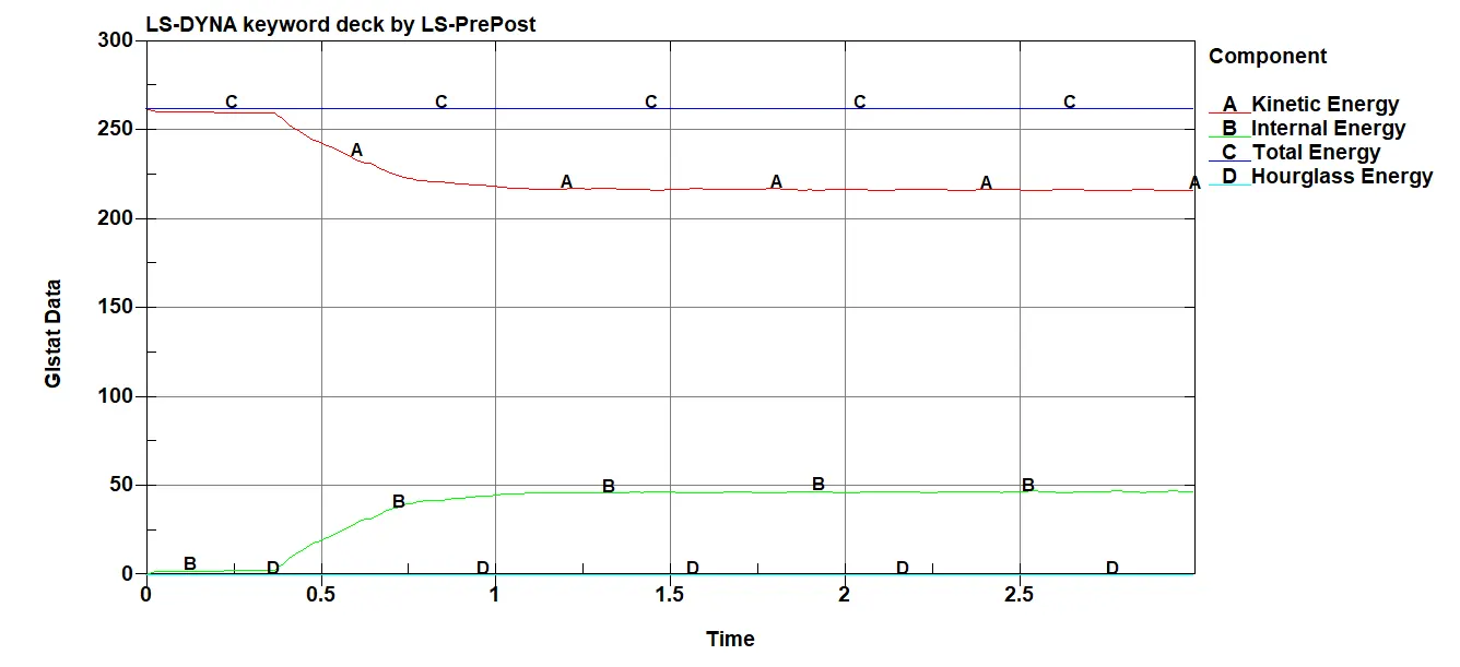
- The above plot shows the Engergy comparison between Kinetic Energy, Internal Energy, Total Energy & Hourglass Energy. It can be seen that as kinetic enegy is decreasing, internal enegy is rising in a symmertical manner..
- Hourglass energy remains zero throughout the simulation.
SLEOUT PLOTS
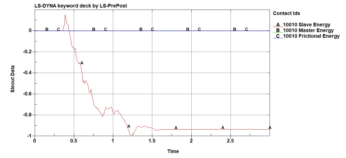
- SLEOUT records all the sliding energy due to contact.
- It can be seen that the master and frictional energy remains at zero whereas the slave energy dips down.
MATSUM PLOTS
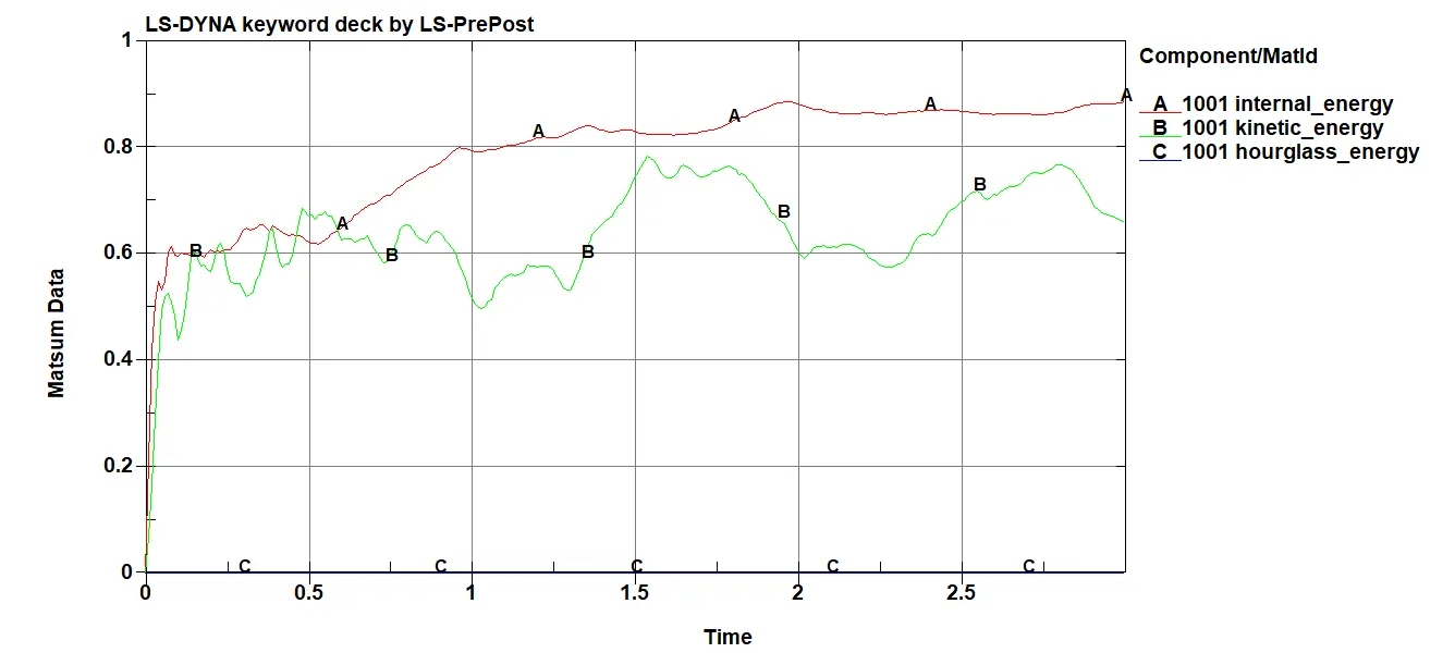
- MATSUM is used to record energy created for each of the part. I.E, K.E and Hourglass Energy can be seen for the Hub part as the result of the rotation of the blade.
DEBUGGING:
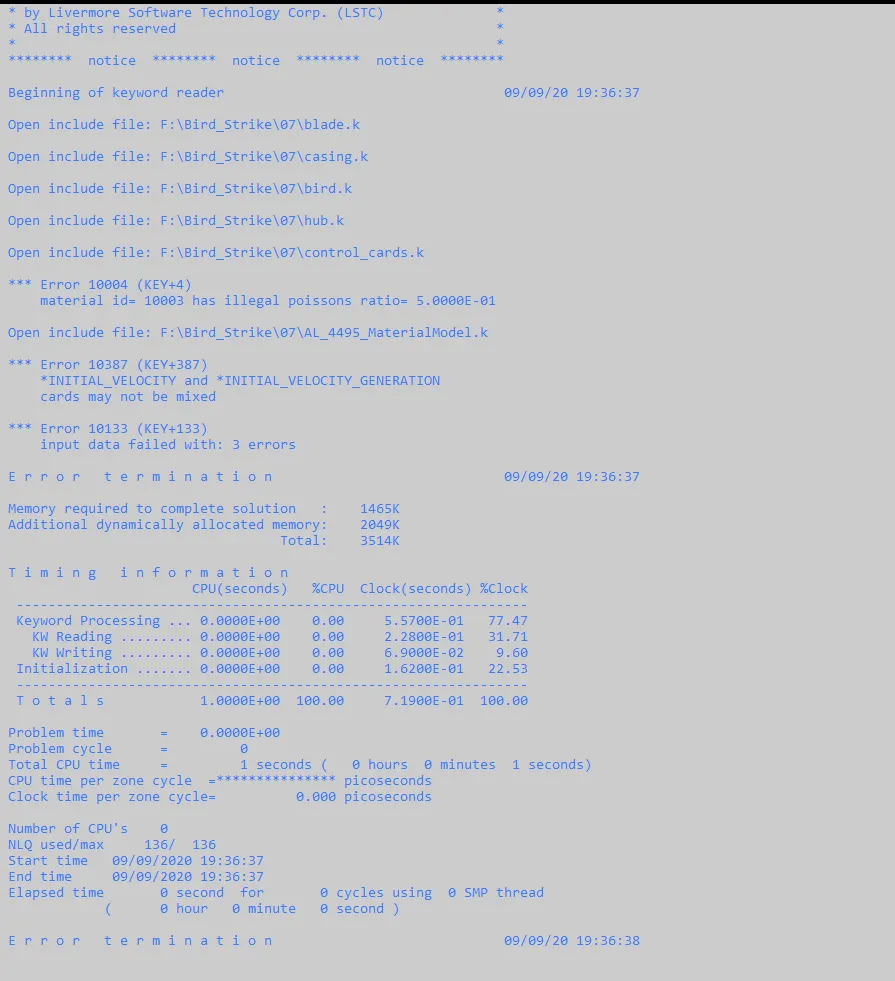
1. The model was tried to run with both initial velocity and velocity generation cards together but it resulted in the error which says both these cards cannot be used together.
Resolution: It has been resolved by using only velocity generation card alone in the model
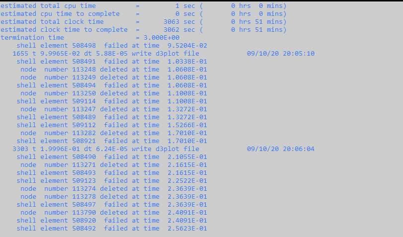
2. The model was tried to run with high velocity (750Km/hr) which resulted in an error in which node numbers and shell elements were getting deleted and sometimes the bird part even go though the model.
Resolution: It has been resolved by reducing the velocity to 180km/hr. The model was getting unstable beacuse the bird and blade material and section were made simple for this simulation which was not capable to handle that much high velocity.
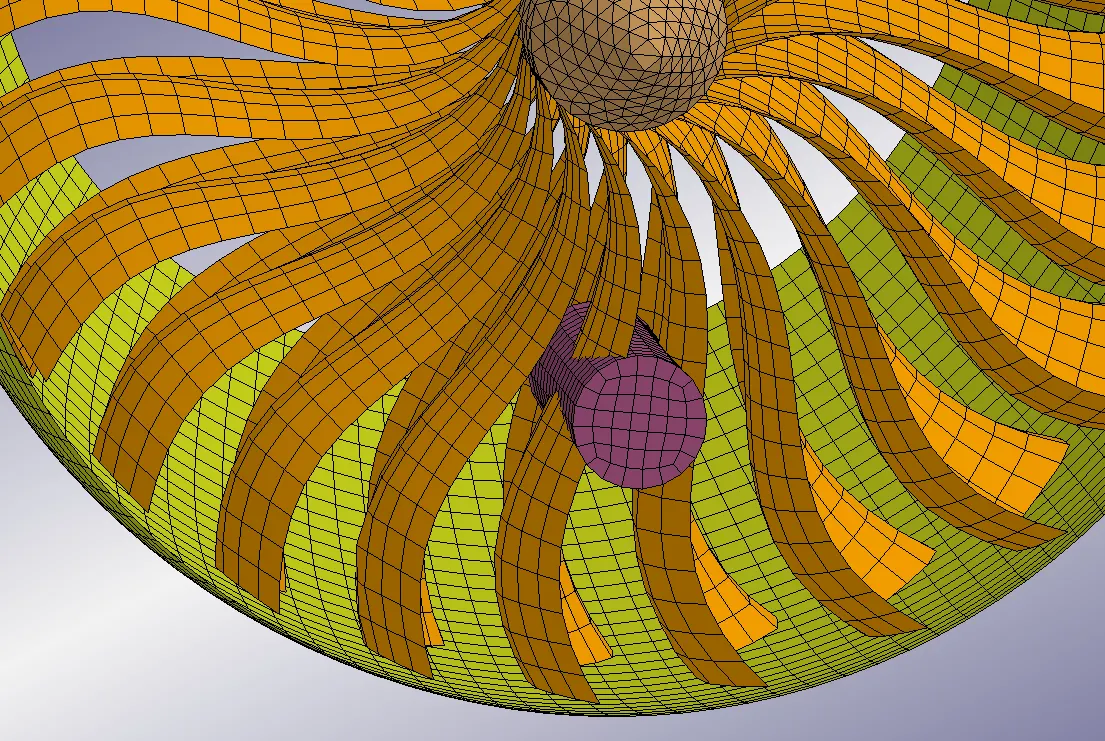
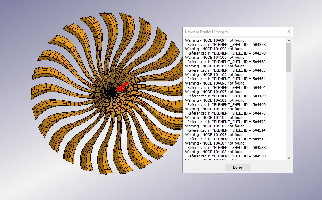
3. After reumbering from the main file, it can be seen that the model was running successfully but at the same time it can bee seen that the nodes which are common to blade and hub are getting thrown out when the blade .key file was opened seperately.
Resolution: To resolve this problem, The parts are seperated and common nodes now wil be having two nodes which are coincided. To connect this two parts, Tied_Node_To_Surface contact is defined between the blade and hub where the hub is defined as the master and the blades as slave as the moving parts are defiend as slaves. This is done to attach the blades to the hub by it common nodes.
CONCLUSION:
A bird strike on an Aero Engine is simulated in an organized and disciplined manner with a consistent numbering approach and using include keyword to call all the seperate files to the main file. From this simultion it is learned how to simulate a simple bird stike kind of problem, how to debugg the issues happening while doing the simulation and also to use mass scaling technique to reduce the run time of the model without compromising the stability of the model.
Note: All the necessary files are attached with this report.
Thanks:)