Side crash analysis of Neon Dodge BIW
Objective:
- To analyse the side crash of a Neon car's BIW as per Federal Motor Vehicle Safety Standard 214 (FMVSS214).
Abstract:
The results of a study on the response of a side impact beam located in a car door to impact loading is presented. The side impact beam is situated in both the front and rear side doors of a vehicle between the inner and outer shells to minimise intrusion into the passenger compartment during a collision whilst absorbing as much impact energy as possible.A numerical model of a light-weight passenger car was used to simulate a side impact collision with a rigid vertical 254mm diameter pole on the front side door at 8.88 m/s (32.2 km/h) in close conformation to the Federal Motor Vehicle Safety Standard 214 (FMVSS214).
Methodology:
The side pole impact test is conducted using a Neon dodge Neon side BIW.The vehicle has an initial velocity upto 20mph.The total simulation time is 80ms.The reason for termination time is that for rigid barriers, deceleration rates are very high.
Procedure:
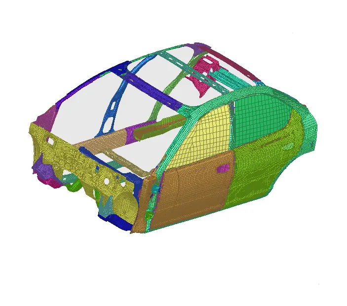
1.We import the model
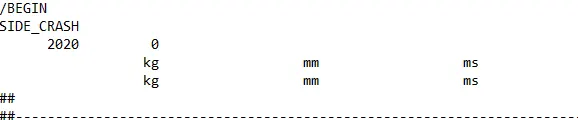
2.We check for the unit system.
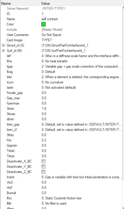
3.We need to create a self contact interface inorder to avoid penetration and intersection in the model.Both master and slaves are connected to each other.
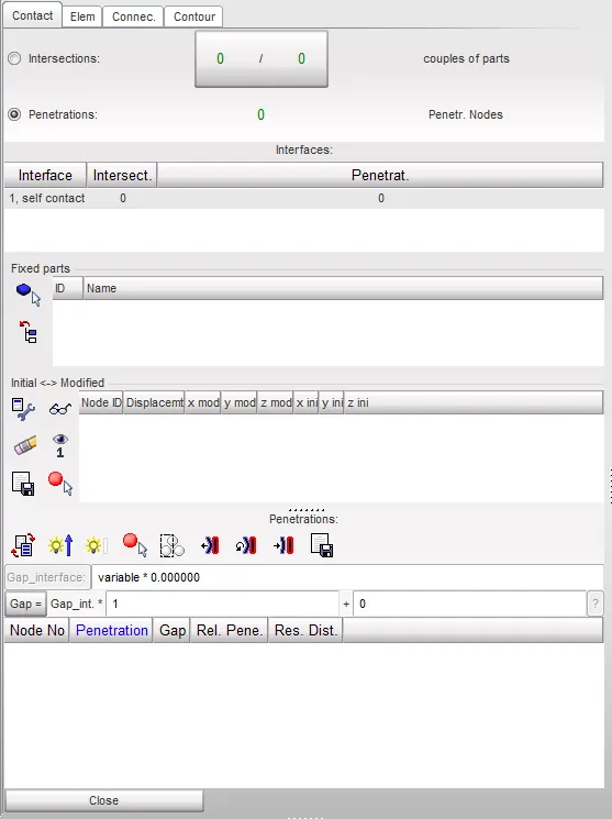
4.Then the model should be checked for intersections and penetrations.There were no intersections or penetrations in the system.
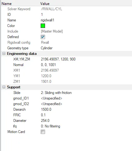
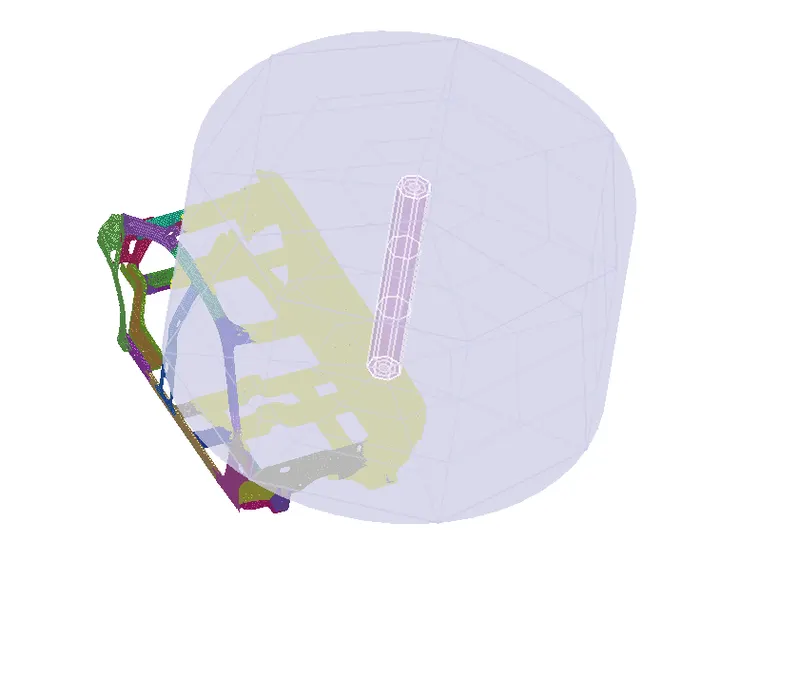
5.In side impact,We check for cylindrical rigid barrier.To create a cylindrical rigid barrier with a search distance of 1500 with friction as 0.1,
From the standard FMVSS no.214 nrigid wall dia is 10 inches (254mm)
6.Mass balancing:
As we have removed most of the components from the model, We need to set the CG point for the car.
To add mass,We create ADMAS cards from the solver.

A total of 700kg is added to achive the CG point of the car.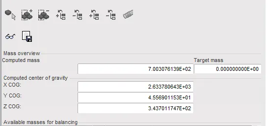
We achieve CG point perfectly in the BIW.
7.To set the initial velocity of the car, we need to chek the standard for a standard value.
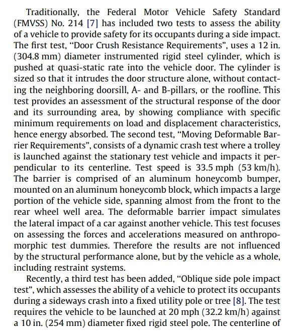
From the standard ,we can get the value of velocity as 20mph or 32.2km/h
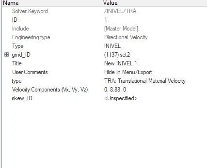
To set the intial velocity,Create INIVEL card in the solver.
Initial velocity is 2.88mm/ms when converted from miles, in global Y direction.
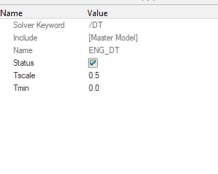
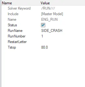
8.Timestep and termination time: Time step given is 0.5ms .Termination time is at 80ms.
Time step is given by creating DT card.
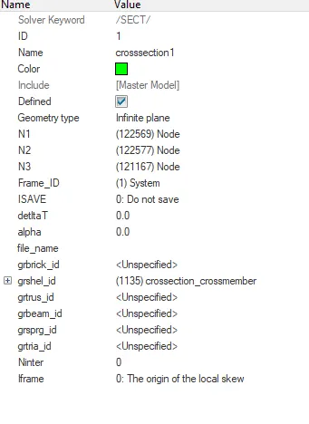
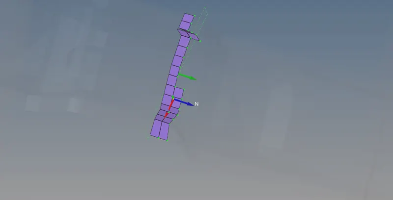
9.We need to check the sectional force in the cross member.
For that,a cross sectional plane is required,To create that, a reference frame is required.
To create the section,One new SECT card should be selected.
10.
- To check the intrusions,we create a TH card with node selecting two nodes near B piller,Hinge piller and fuel tank region.
- Before that, a skew should be created with respect to the node in a place where much displacement is not happening.
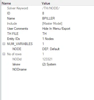
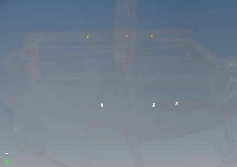
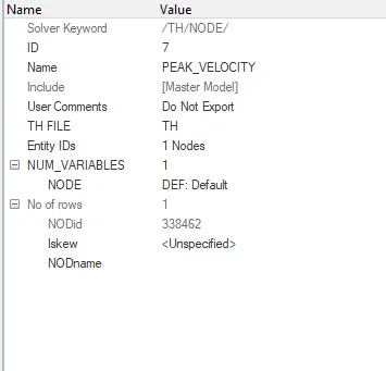
11.To find the peak velocity on door,We create TH card for the selected node to get the output value for the peak velocity.
Conclusion:
We get an animation like this,
From the animation we can conclude that car hitting cylindrical wall will experience high force and causes bending.
Sectional force in the cross member:
When the cross member in car attached to B piller experiences a brutal force,
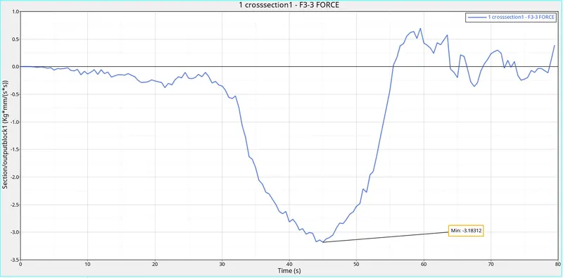
- Force oscilllation in the cross-section can be figured out in the graph as the force is a vector and it changes its direction when the bending happens in the component.
- Whenthe car hits cylindrical barrier,cross member experiences a high value of force which is 3.18KN
- Then when the bending happens in the cross member,it experiences a less force.
Intrusion in B-piller:
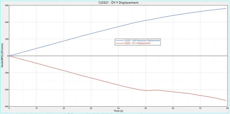
- There will be an initial displacement in the node when car starts.
- A bulge in the orange curve defines the displacement in the node after crash
- Displacement in y- negative direction is the actual displacement of the node.
Intrusion in Hinge piller:
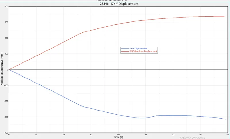
- When the crash happens ,there will be a sudden displacement in the node.
- This displacement is because of bending.
- This is the maximum displacement happening for 80ms.
Intrusion near fuel tank:
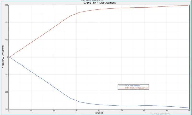
- Intrusion near fuel tank will be gradually increasing
- As it very near to rigid wall,displacement will be faster.
- Displacement value is about 300 mm
Peak Velocity of a node in the door:
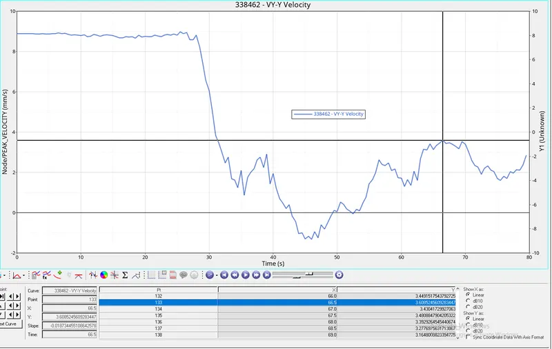
- Car crashes rigid wall with an initial velocity of 8.88mm/ms
- When it hits the rigid wall, there will be a velocity drop in the node.
- After that due to bending of the door ,there will be an induced velocity in the node,
- Peak velocity of the node after crash is near 3.60mm/ms2
Energy plot:
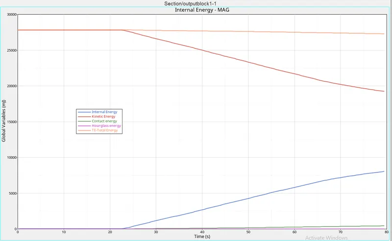
1.Kinetic energy:
- When the B-piller crashes the rigid wall hard,then there will be a sudden spike in kinetic energy as the b-piller absorbs energy more beacause of its solidity.
- After that there will be a gradual decrease in the kinetic energy because of velocity drop in the car.
2.Internal energy:
- When the car hits rigid wall,velocity of the car decreases and it will get crushed.
- Because of crushing,There will be molecular movement in components which will induce internal energy.
- So the internal energy will gradually increase in the vehicle.
3.Contact Energy:
- Contact interfaces are defined with friction of 0.2.
- Because of friction defined,there will be a slight contact energy induced which is minimal.
4.Hourglass energy:
- As QEPH is used which is not fully integrated,There will be a slight space for hourglass energy.
- Hour glass energy as compared to vehicle is minimal.
5.Total energy:
- Total energy is the summation of all the eneries mentioned above with other traslational and rotational energies.
- This curve will remain almost constant through out the simulation.
From the energy dissipation curve we can conclude that most dissipation is happened only on bpiller and doors and then to other components such as cross members.
ERRORS FACED:
- ALTDOCTAG file was present in HYPERCRASH.
- Frame was not reffered to the cross section.
References:
Researchgate ,Wikipedia