Frontal crash analysis of Neon Dodge BIW
Objective:
- To analyse the frontal crash of a car's BIW as per the FMVSS(Federal Motor Vehicle Safety
Standard ).208
Abstract:
Every year National Highway Traffic Safety Administration evaluates crash safety for cars all around the world.Tests are conducted to measure how people inside the car are protected in a head-on cxollision.Based on the resultfrom the test, the vehicle is given a one to five star rating, five stars being the most protective and one being the worst. The crash test ratings are only meaningful when comparing vehicles within the same weight class. Federal law requires all passenger cars to pass a 30 mph frontal crash while the NCAP test involve crashing into a fixed barrier at 35 mph. Instruments are placed in the vehicle to record the response of the structure during the crash. Anthropomorphic dummies are placed in the driver and passenger seats for the test, they measure the force of the impact to the chest, head and leg. These readings are the basis for the five start rating.
Methodology:
The frontal impact crash test is conducted using a Neon dodge frontal BIW.The vehicle has an initial velocity upto 35mph.The total simulation time is 80ms.The reason for termination time is that for rigid barriers, deceleration rates are very high. Numerous instrumental tests carried out in the past show that most energy transfer in a head-on or frontal vehicle impact with a rigid barrier occurs within 0.2 seconds and can be as short as 0.07 to 0.02 seconds.
Procedure:.
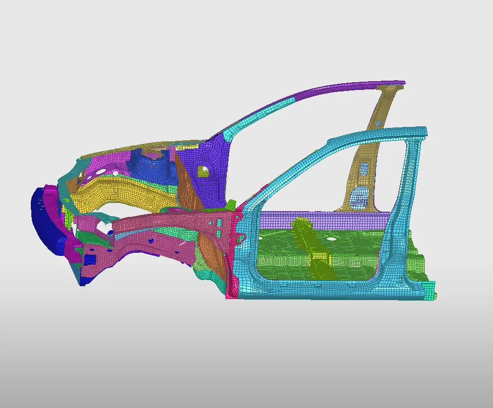
- Import the model.
2. Check for the unit system.
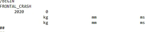
It is kg,mm,ms and we keep it in the same way.
3.Properties and material cards are created as required.
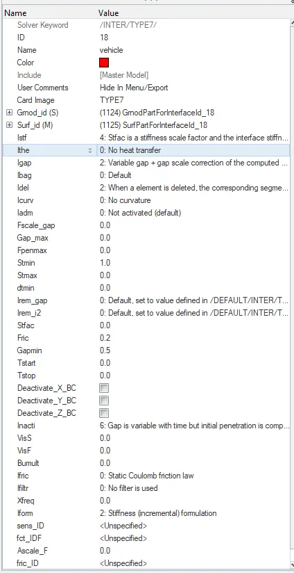
4.A type 7 node-node self contact is defined to create interface between the components.
5.Penetration check should be done for the created self contact.
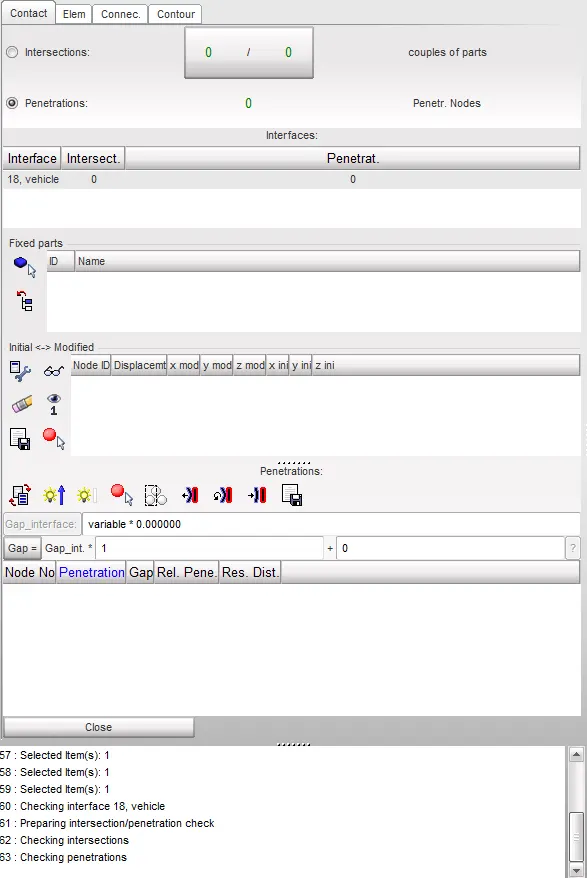
We found zero penetrations and intersections.
6.Then check for extra rigid bodies or if we find any issues with the rigid bodies.
So we find 2 extra ridig bodies that aren't required.So we delete those rigid bodies.
7.To create a rigid wall,
- We select a point in the bumper region of car.
- Then,a search distance of 1500mm is given.
- Normal axis should be opposing the initial velocity of car.
- Sliding with friction is selected to get more accurate results.
- Friction value is given as 0.2
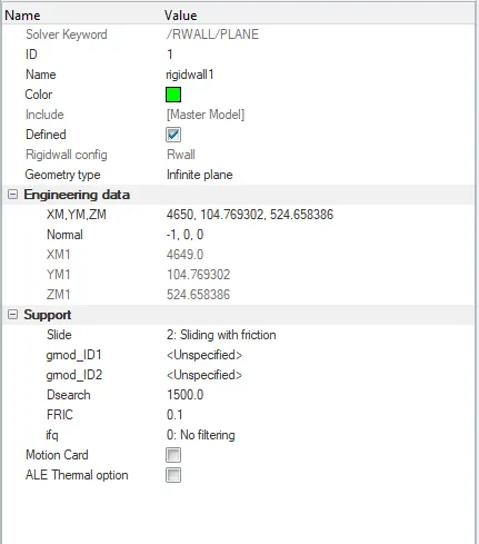
- A rigid wall is created.
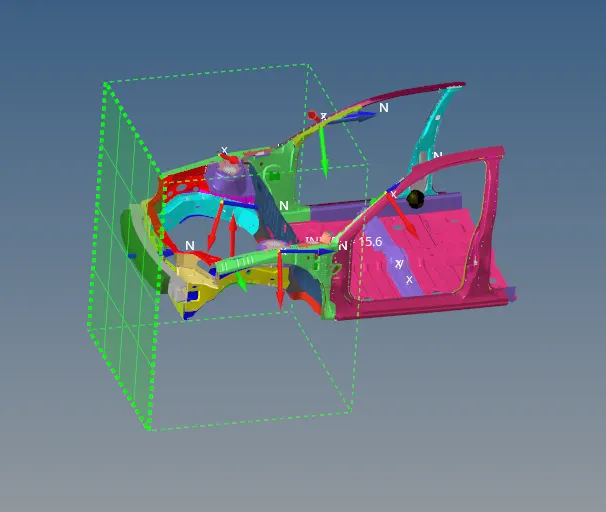
8.As we have removed too many components from the full model,We need to set the CG point of the car.For that,we are adding mass to the system.
- To add mass,We create ADMAS and we add weight to components and nodes.

- Also we need to achieve a target of 700kg,which is by adding mass through ADMAS,
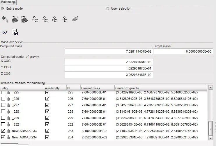
- A target weight of 700kg is achieved,so we check for the CG point of the car.
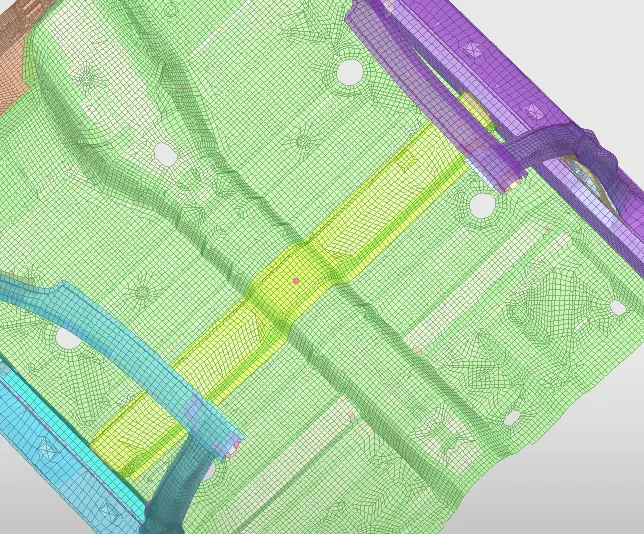
- As CG is in the middle,We get the results quite accurate.
9.To introduce initial velocity,From the standard we take initial velocity of 35mph i.e.,15.64 mm/ms.
- So we create a INIVEL card and we give 15.64mm/ms as initial velocity in the global x direction as it is directed towards front of car.
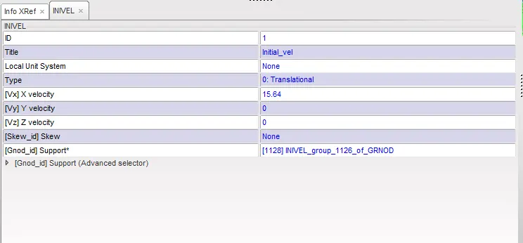
- It is shown as a big arrow mark in Hypercrash.

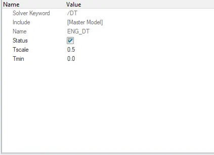
10.Then we create time step for the model.To create time step,Go to Solver>Create >DT.
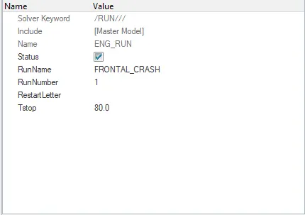
11.Runtime is entered to RUN file.
Cross-section on A pillers,Shotgun And node number 174247:
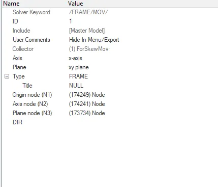
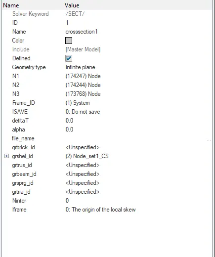
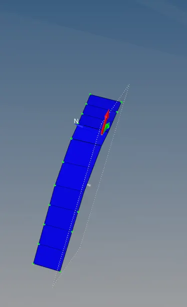
- To get output files for cross-sectional forces ,we need to have 1 set of elements,1 Frame and one section cards to be generated.
- At first,We create a element set,Then we create a frame and then a section.
- Cards are shown here,then the cross section.
Axial forces on bumper and rail:
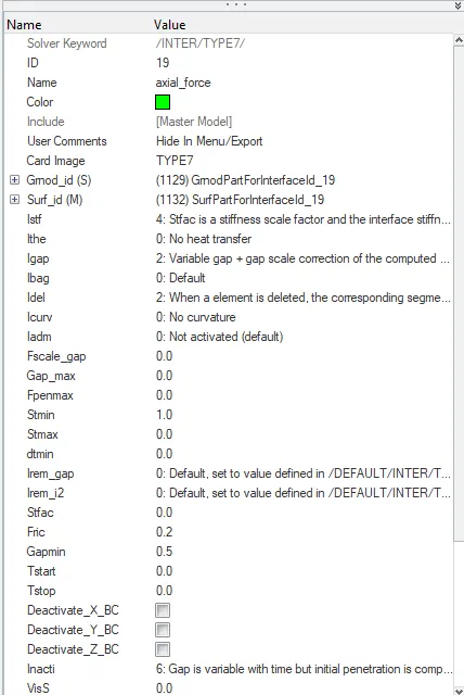
- A Type 7 interface is created between Bumper and Rail.
- Bumper is taken as Master because of its higher stiffness.
- Rail is selected as slave.
Accelerometer Sensor:
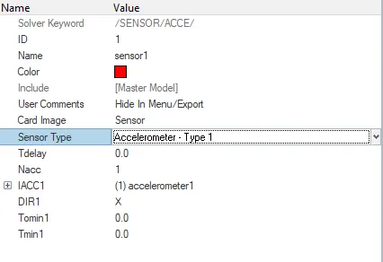
- We need to create a accelerometer to find the accelaration in the bpiller rocker.
- For that, We create a accelerometer using ACCEL card in Hypermesh.
Intrusions on break,clutch paddles:
- To check the intrusions,we create a TH card with node selecting two nodes near paddles.
- Before that, a skew should be created with respect to the node in a place where much displacement is not happening.
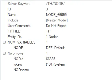
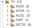
To get the TH graphs,We need to create Time history for all the nodes,accelerometer & sections.
RESULTS:
We get a output simulation for the frontal crash.
From the animation,
We can conclude that BIW is sliding upwards to the rigid wall after crash.
This is because of improper mass balancing in the BIW.As this is not a complete model so some mass is added to nodes to match complete model.
Cross section in rails:
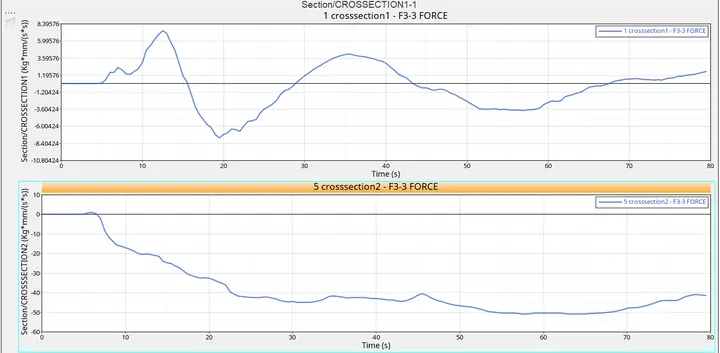
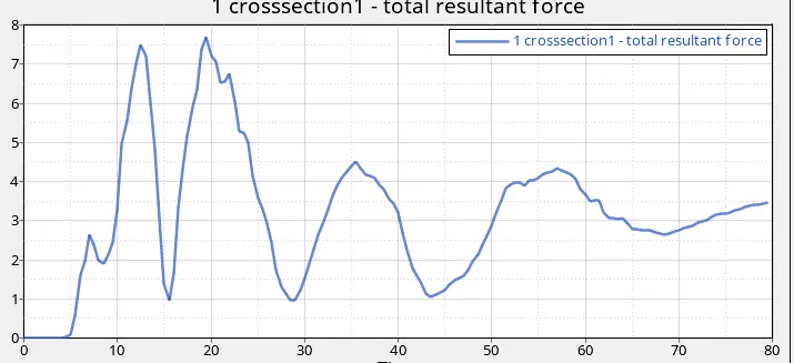
- In the rails,when the bumber hits the rigid wall,there will be a force induced.
- Because of deformation, component or the shells in it will bend.
- Because of bendness,the normal axis z will change the direction at times.So the force value is negative at times.
- But the total resultant force is positive as it is a summation of all the forces acting on it.
Cross section of Shotguns:
Shot gun forces along local normal axis-z are
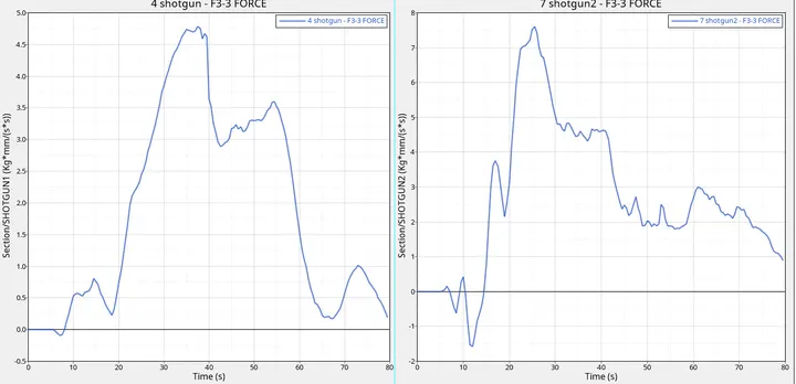
So when the maximum bending occurs in the shotgun,We can see a maximum force is achieved.
Axial force on rails recieved from the bumper:
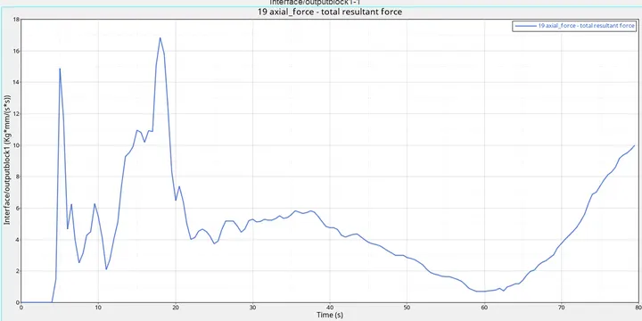
- Axial force on rails will be high when the bumper hits the rigid wall.
- At the maximum point of force the rails will get crushed.
- Because of sliding of bumper on rigid wall,again bumper will enforce rails so that forces on rails gradually increase.
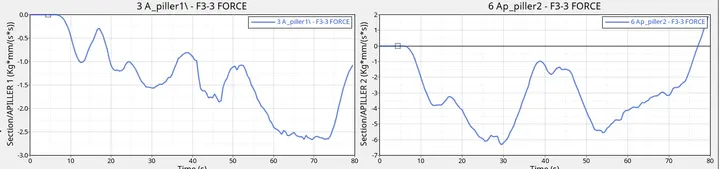
Sectional forces in A_pillers:
Acceleration on B-piller rockers:
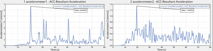
- Maximum accelaration value is 6.63mm/ms2 & 1.34mm/ms2 for both accelarometers.
- Accelaration changes due to the kinetic energy drop in the vehicle.
- Accelaration defers in both the sides because of improper mass balancing.
Intrusions on the dash wall 66695,66244:
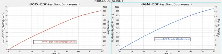
- Resultant displacement is shown in the above figure.
- displacement in length is about 894mm for that node.
- This was measured with respect to a skew.
- This is the displacement that is going to happen after 80 ms.
Energy plot:
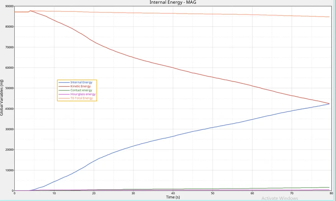
1.Kinetic energy:
- When the bumper crashes the rigid wall hard,then there will be a sudden spike in kinetic energy as the bumper absorbs energy more beacause of its solidity.
- After that there will be a gradual decrease in the kinetic energy because of velocity drop in the car.
2.Internal energy:
- When the car hits rigid wall,velocity of the car decreases and it will get crushed.
- Because of crushing,There will be molecular movement in components which will induce internal energy.
- So the internal energy will gradually increase in the vehicle.
3.Contact Energy:
- Contact interfaces are defined with friction of 0.2.
- Because of friction defined,there will be a slight contact energy induced which is minimal.
4.Hourglass energy:
- As QEPH is used which is not fully integrated,There will be a slight space for hourglass energy.
- Hour glass energy as compared to vehicle is minimal.
5.Total energy:
- Total energy is the summation of all the eneries mentioned above with other traslational and rotational energies.
- This curve will remain almost constant through out the simulation.
From the energy dissipation curve we can conclude that most dissipation is happened only on bumpers and rails and then to other components such as A-piller or B-piller.
ERRORS:
- Found some extra springs while performing the simulation.
- An unsupported card called ALTDOCTAG wa s present in the radioss file.
- Found an unsupported section id error.