Assignment 3-2D Element Formulation Challenge
AIM:
Comparison of results with base simulation and improved shell element properties
1.Using the crash beam file from the previous assignment, change the run time to 55 ms.
2. Change the number of animation steps during simulation to a minimum of 25 and maximum of 60.
3. Run the base simulation without any modification to element properties.
4. At the end of the simulation, do the energy error and mass error checks and determine whether results would be acceptable.
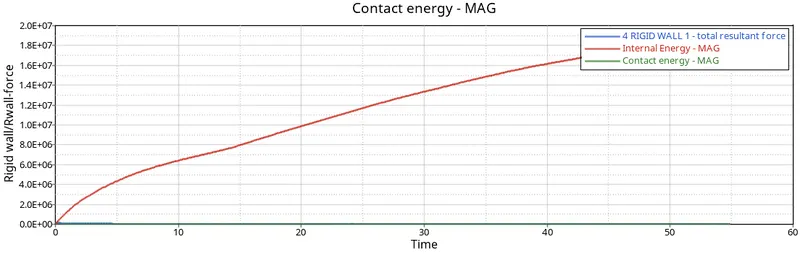
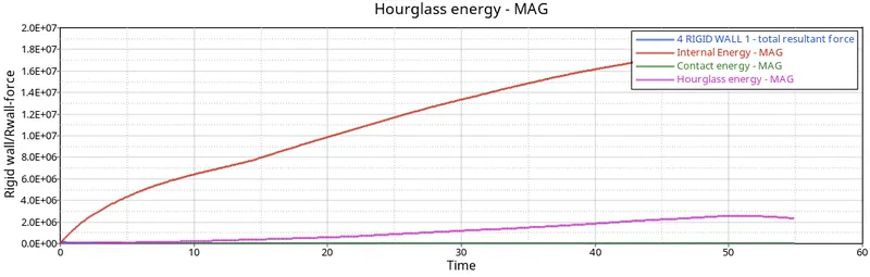
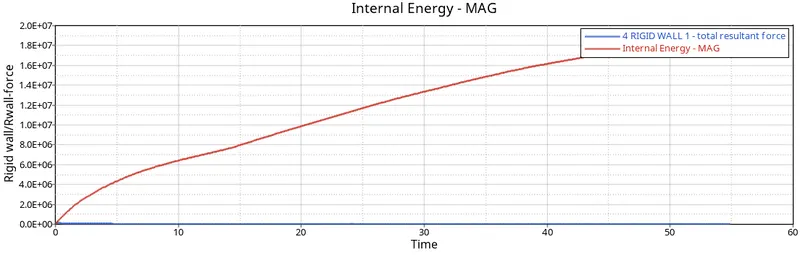
5. If acceptable, Plot rigid wall forces, internal energy, hourglass energy, contact energy, total energy of the simulations.
6. Change all the shell elements properties to recommended properties, save this as separate, rad files and run the simulation.
7. Follow steps 5 and 6.
8. Create a brief report comparing all the results from steps 5 and 6 for both simulations.
9. Comment whether there is any change in the results and why there is any change in the result.
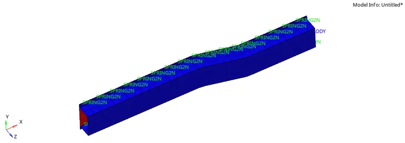
MODEL:
PROCEDURE:
CASE1:
Running the file with default properties.
1.Import the radioss file into the graphical user interface using Import-sover deck
2.Change the run_time to 55ms in the ENGINE_RUN CARD.
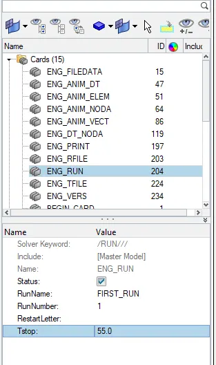
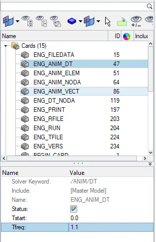
3.Change the number of animation steps to 50 as mentioned in the question (25-60)
4.Calculate Tfreq=Runtime/no of anim.steps = 55/50 = 1.1
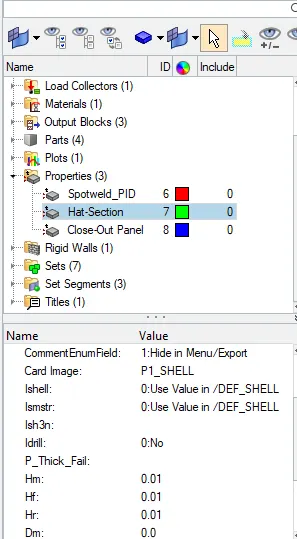
5.The properties shall remain with the default values and we need to run the simulation.
6.To run the simulation go to Analysis-Radioss
7.In the options panel mention -nt 4. nt stands for number thread as it makes to run the simulation faster.
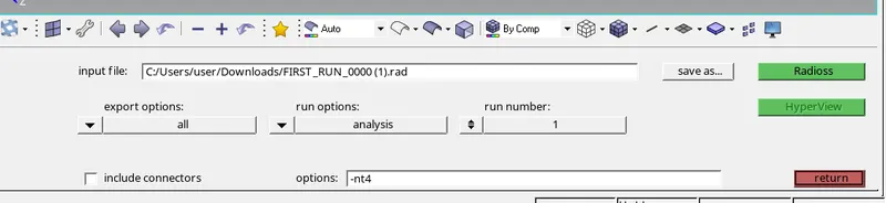
8.Click on Radioss and the simulation will be done
9.After the simulation then go for results.
10.Go to hyperview to view the result and the animation.
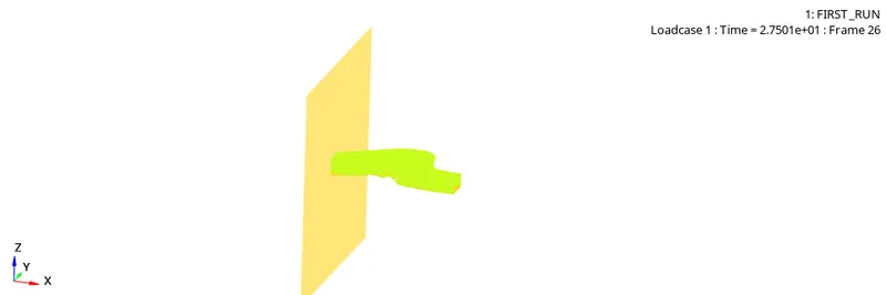
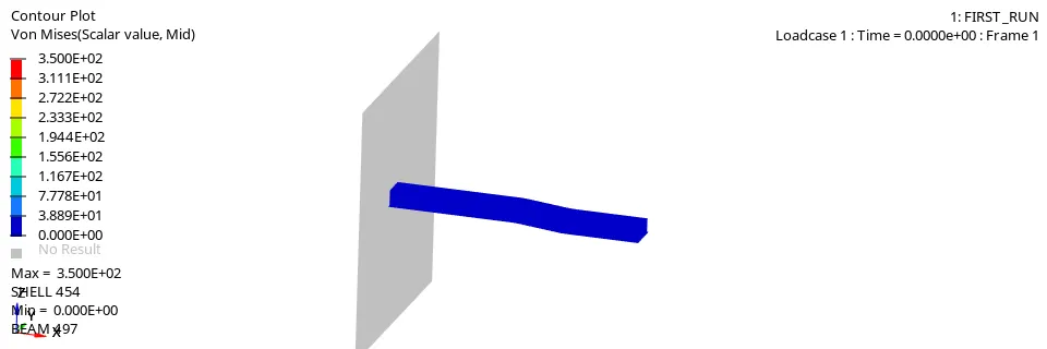
11.Switch to contour mode.
12.Select the type of result we want to view and click apply.
13.For example select vonmises stresses
14.We can find the output results such as mass and energy error in 0001.out file.
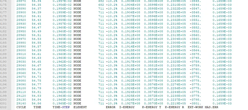
15.Safe tolerance is -15% to +5%.
16.The obtained value is within the range ,so the simulation results are aceeptable.
17.Plot the required graphs if the results are acceptable.
18.Go to hypergraph 2d and import the FIRST_RUNT01 File.
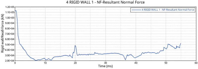
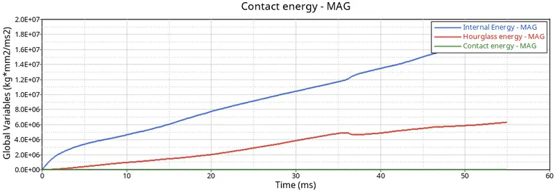
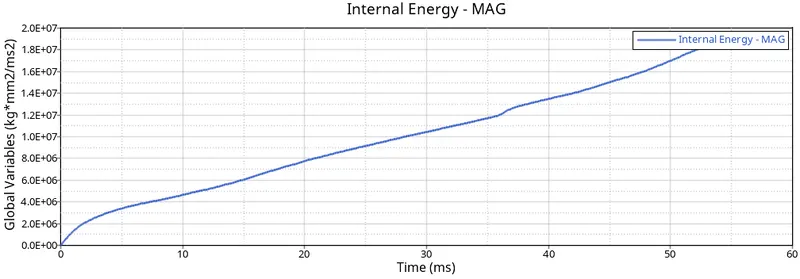
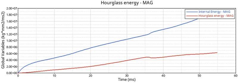
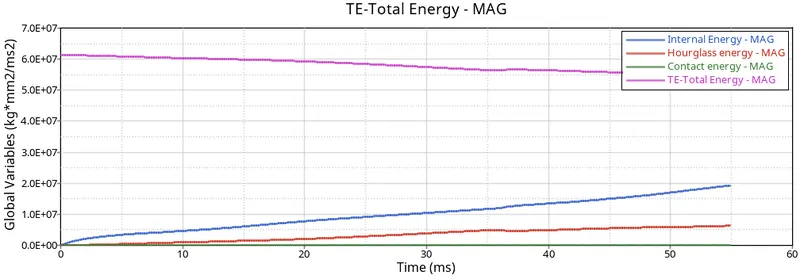
19.Plot the below graphs.
CASE2:
ASSIGN THE RECOMMENDED PARAMETERS IN THE PROPERTY.
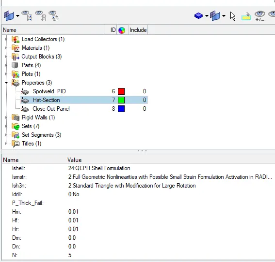
2.After assigning run the simulation as the previous one.
3.View the results in hyperview tab.
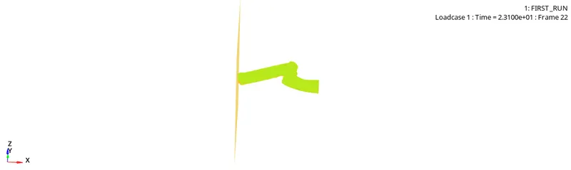
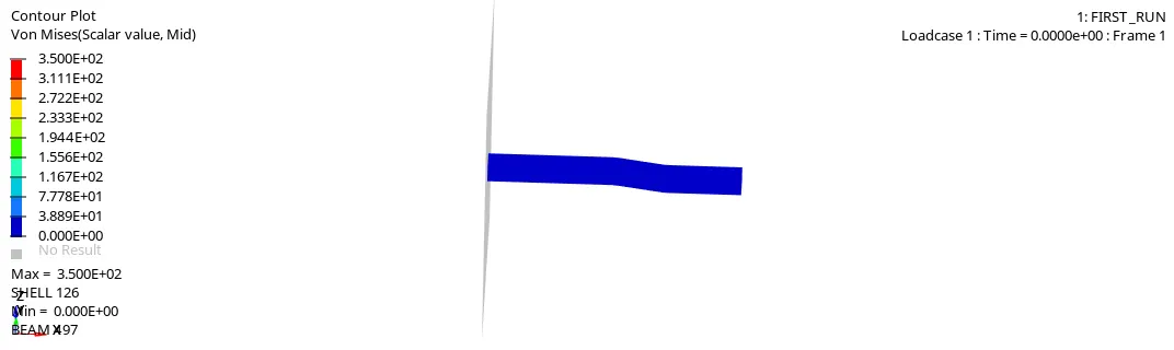
4.View the mass and energy errors in 0001.out file.
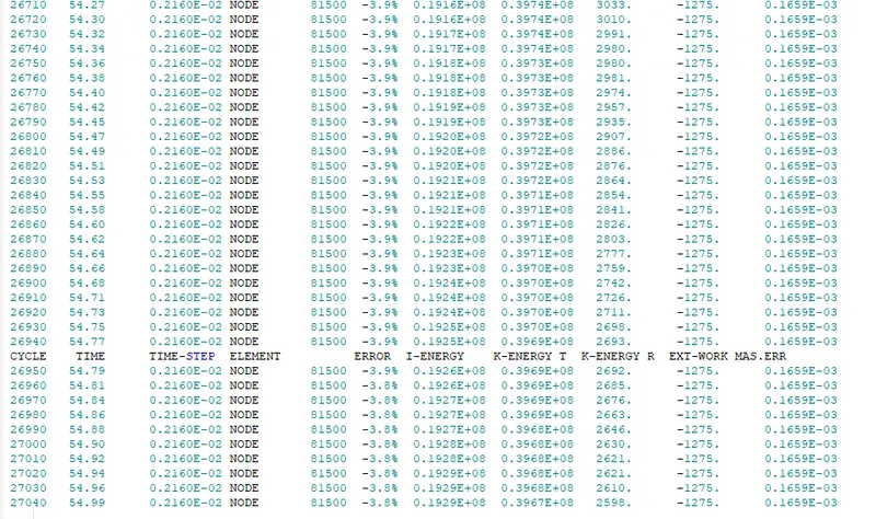
Safe tolerance is -15% to +5%.
5.The obtained value is within the range ,so the simulation results are aceeptable.
6.Plot the required graphs if the results are acceptable.
7.Go to hypergraph 2d and import the FIRST_RUNT01 File.
8.Plot the below graphs.
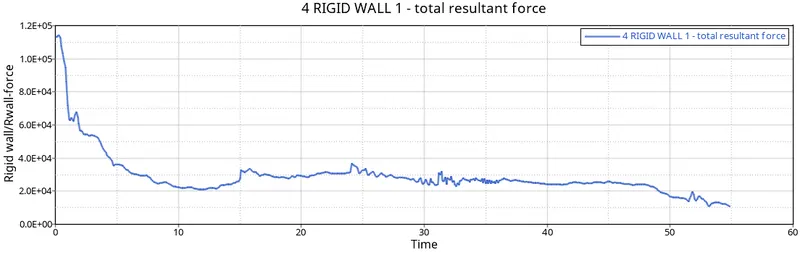
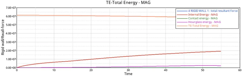
COMPARISION BETWEEN BOTH RESULTS:
1.The energy error obtained in case1 is -10.3% while in case2 is -3.8%.
2.The maximum internal energy obtained in case1 is 1.8E+07 and in case 2 is 1.6E+07
3.The hourglass energy n case1 is varying and is constant in case2.
4. case1 requires hourglass energy to energy balance and case2 doesnt require.
5.Rigid wall forces also decreased to a lower value.
6.The results are less accurate in case1 and more accurate in case2.
HOURGLASS ENERGY
When elements in a model deform but strain energy is not computed for that deformation then it results in hour glasss deformation.
usually seen in post processing where elements will have zigzag formation.
Hourglass modes are nonphysical modes of deformation that occur in underintegrated elements and produce no stress. By underintegrated, we mean One point integration is much faster so we usually tolerate, but try to minimize, hourglass modes.
Consider a 4 noded Rectangular shell element called as S4 element. They may have any number of Integration points (depending upon full or reduced integration). Stresses and strains at this element are captured by integrating the values got at these integration points.
It is to be remembered that values are more accurate at the exact location of the Integration point and not so accurate as we move away from it.
For sake of lesser computational time, we can use S4R element which means Reduced Integration where in the one Integration point is used and it is ideally at the centre of the element.
In the case of these Reduced Integration elements, while post processing results, we can see a false or fake deformation mode (zig zag lines). Such a thing is the Hour Glass phenomenon.
To solve this problem,
- Mesh Refining is a solution. Hourglassing is more prone in coarse mesh.
- Fully Integrated elements are better though computational time increases vastly and fully integrated elements are prone to shear locking.
- Providing a small arbitrary stiffness in the mode in which hourglass deforms. This is only a FEA point of view and in actual physical system, there is no such stiffness. This is what is called as Built in hourglass controls.
- Viscous damping.
CONCLUSION:The above questions are calculated and results are compared.