Assignment 5-RADIOSS Interfaces & Study of Effect of Notches Challenge
AIM: To Create the mesh for bumper assembly,mesh size should be 6mm.
Run the crash tube model as it is.
Change the Inacti=6 and run.
Create the type 11 contact and run.
Remove both notches and remove boundary condition on rigid body node then run.
Create a new notch in the middle ,select the whole section and run.
Create a new notch with nodes only from opposing 2 faces and run.
Note:
Plot RWALL forces ,contact forces,internal energy and Create TH/PART for all parts and compare results for all cases.
Comment your thought on why there is a change in the internal energies.
How does the notch affect the results?
Plot energies and note any difference.
MODEL:
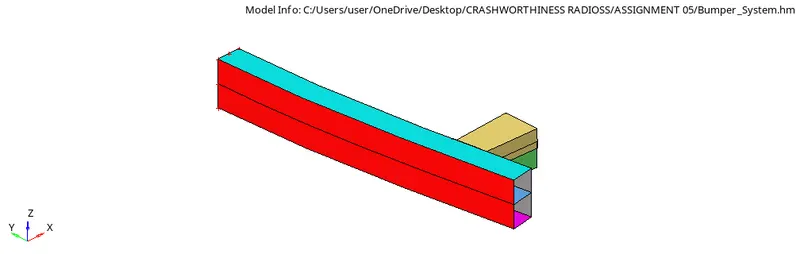
PROCEDURE
STEP1: Import the .hm file into the hyperworks GUI.
STEP2:Check for any geometry errors and correct them if present.
STEP3:Set the criteria for element size as 6mm.
STEP4:Mesh surface by surface and avoid trias .
STEP5:The given bumper system is meshed with 6mm mesh.
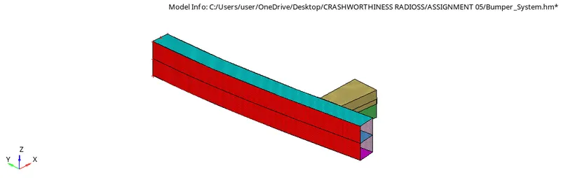
Run the crash tube model as it is.
Change the Inacti=6 and run.
Create the type 11 contact and run.
Remove both notches and remove boundary condition on rigid body node then run.
Create a new notch in the middle ,select the whole section and run.
Create a new notch with nodes only from opposing 2 faces and run.
1.Import the 0000.rad file into the GUI.
2.Run the model with the default parameters.
3.We can see that TYPE2 AND TYPE7 interface is used in the model.
4.Go to Analysis-Radioss-Check include connectors and type -nt 4 in the text box and click radioss.
5.The simulation is running and after it completes go to hyperview to view the results.
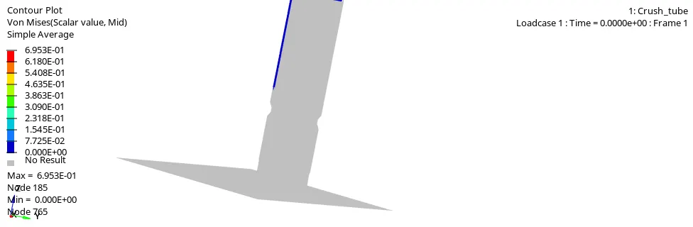
6.
6.Find out the mass and energy error from the .out file.
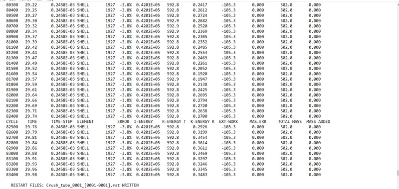
7.We can see that the energy error is -3.8% and mass error is 0% which is highly acceptable
8.So we need to plot the graphs usng hypergraph.
9.Open hypergraph 2d and import the .T01 FILE.
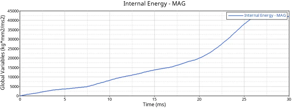
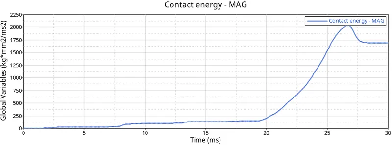
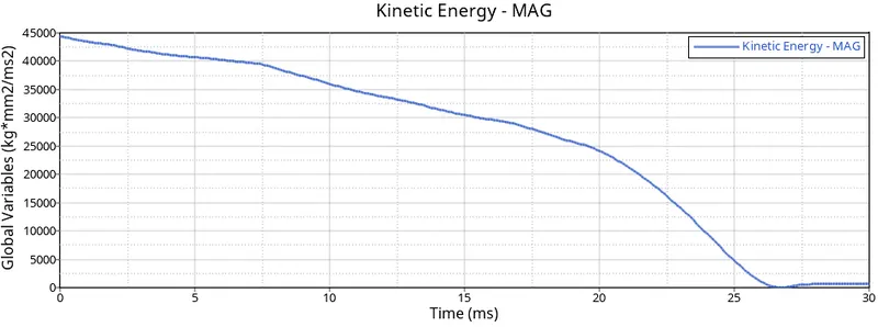
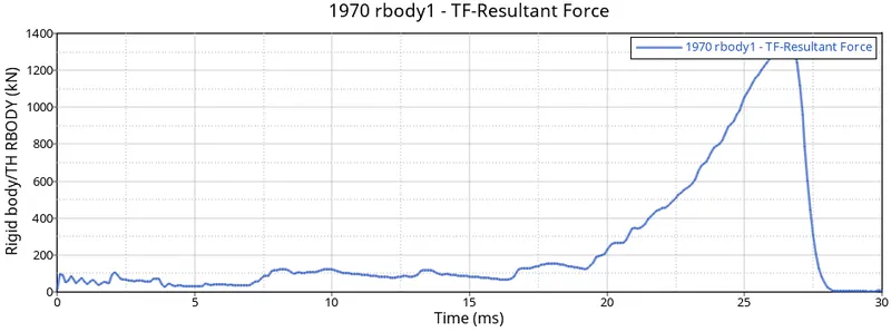
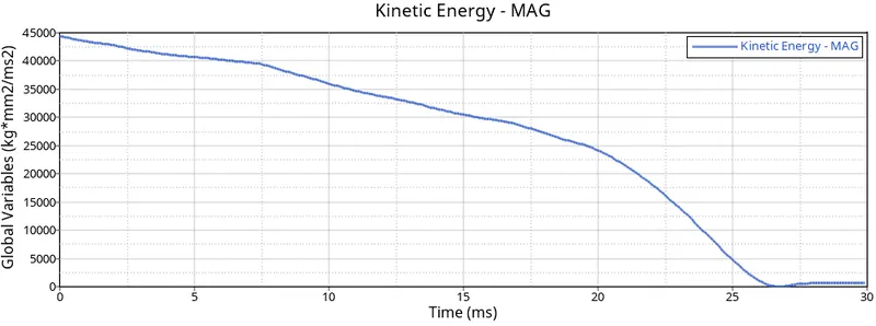
10.We can observe that the kinetic energy is maximum at beginning and decreasing once crash tube hits the rigid wall.
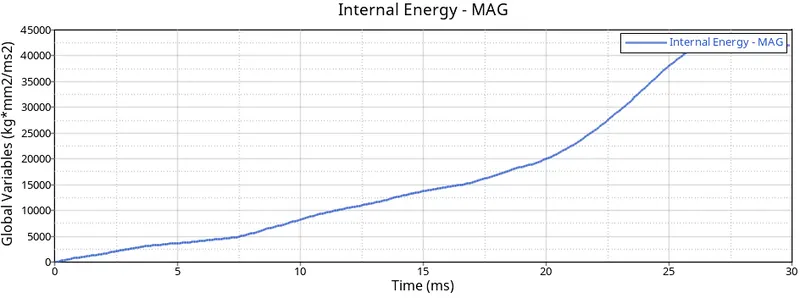
11.We can also observe the increase in internal energy.
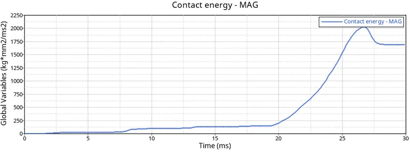
12.The contact energy is varying slowly at beginning and suddenly it is rised due tolarge energy due to deformation at the end.
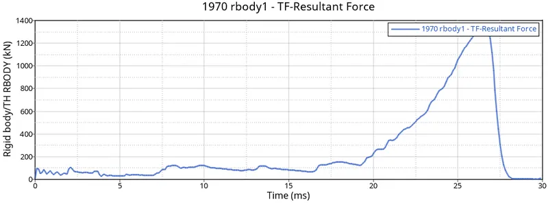
13. Due to large deformation the Rwall force is observed till 1400 kn
CASE2:Change the Inacti=6 and run.
1.Change the Inacti to 6 which means gap is variable with time and initial penetration is computed.
2.Run the simulation with the same previous steps.
3.The mass and energy error is shown below.
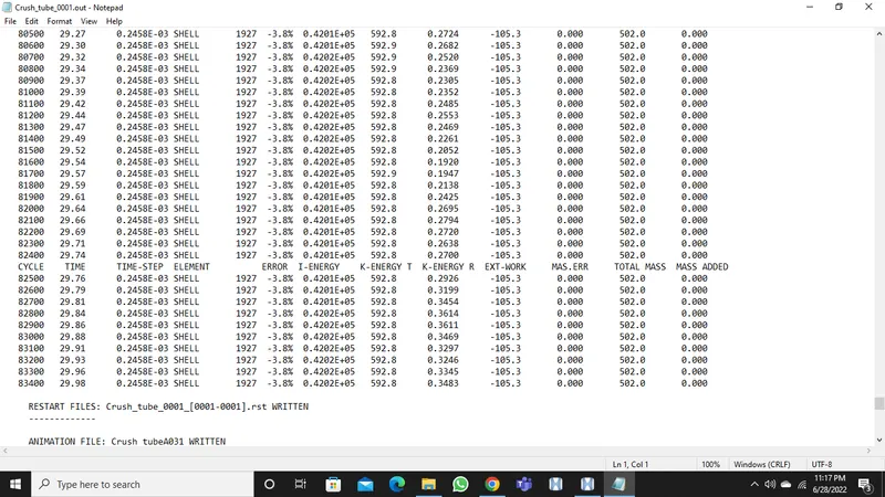
4.We can see that the energy error is -3.8% and mass error is 0% which is highly acceptable
5.So we need to plot the graphs usng hypergraph.
6.Open hypergraph 2d and import the .T01 FILE.
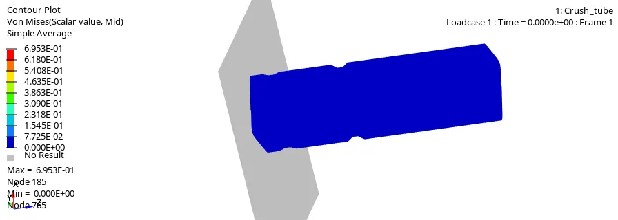
7.We can see that the maximum stress is 69.53n/mm2.
8.The internal energy is increasing at the begininning because it is attached to rigid wall and it deforms smoothly at notch area where there is less stiffness.
9.The KE is varying at beginning and then it remains constant.
10.The contact energy is varying slowly at beginning and suddenly it is rised due tolarge energy due to deformation at the end.
11.The overall elements are becoming compressed and Rigid wall forces are 1400kn
CASE3:Create the type 11 contact and run.
1.Import the file and change the card image to type11
2.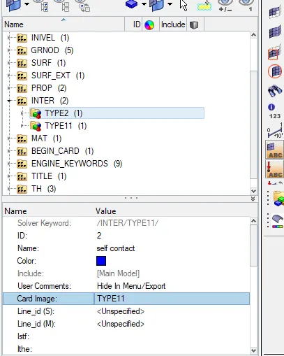
3.TYPE11 connects the edges of slave to edges of the msater segment and improves the force calculatons accuracy.
4.Use the TYPE7 card also for better accuracy.
5.Follow the previous steps to run the simulation and then view the results.
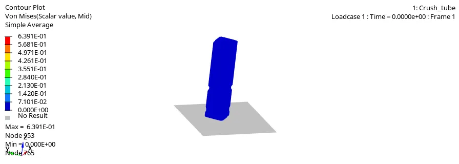
6.Plot the graphs as shown below.
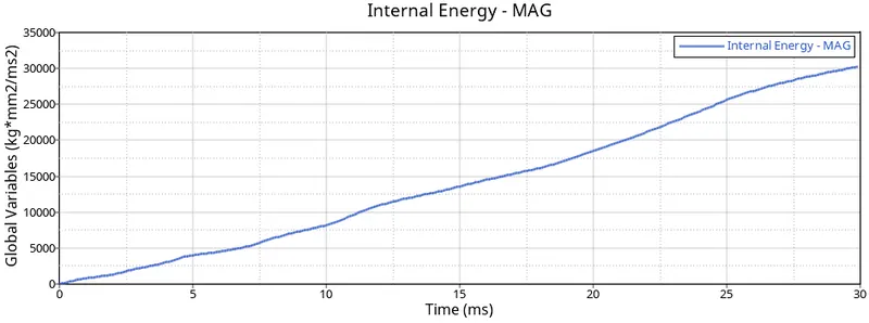
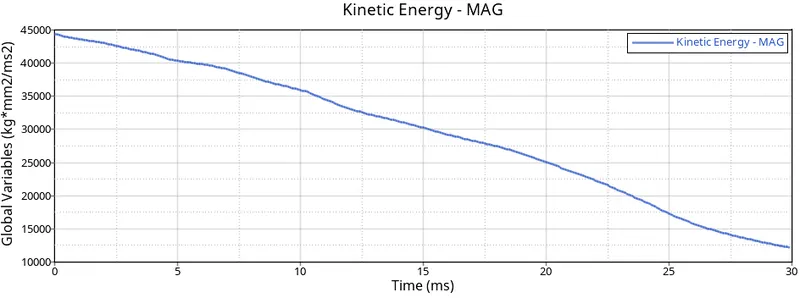
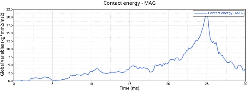
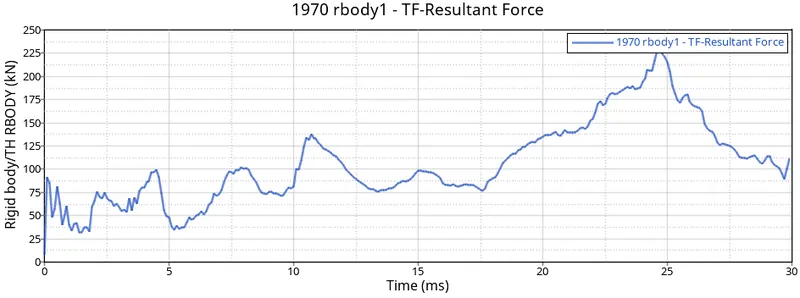
7.The maximum stress obtained is 63.91N/mm2.
8.The internal energy is increasing at the begininning because it is attached to rigid wall and it deforms smoothly at notch area where there is less stiffness.
9. The KE is varying at beginning and then it remains constant.
10.The contact energy is varying slowly at beginning and suddenly it is rised due tolarge energy due to deformation at the end.
11.The overall elements are becoming compressed and Rigid wall forces are 225kn
CASE4:Remove both notches and remove boundary condition on rigid body node then run.
1.In this case notch is to be deleted and it should be a plane mesh.
2.In order to delete go to F2 and select elements to delete and create a plane mesh using ruled option.
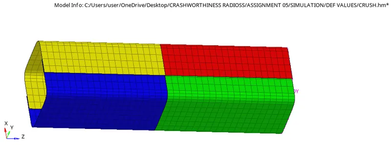
3.Follow the previous steps to run the simulation and then view the results.
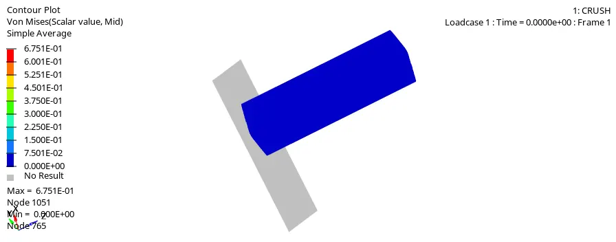
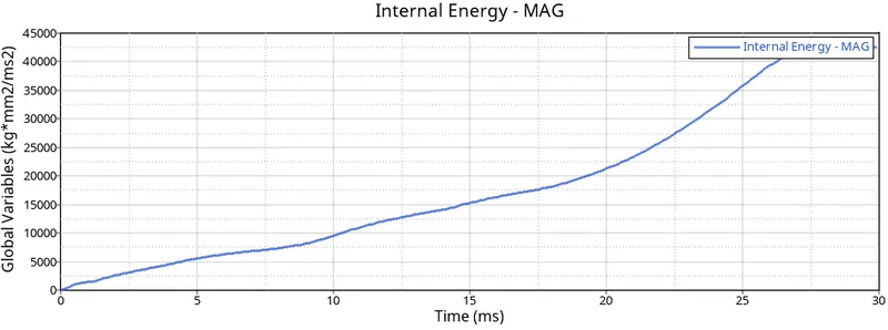
4.Plot the graphs as shown below.
 3
3
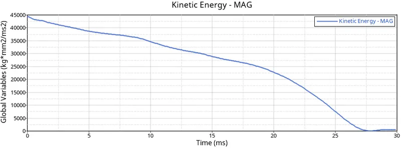
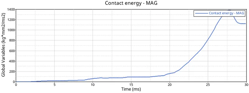
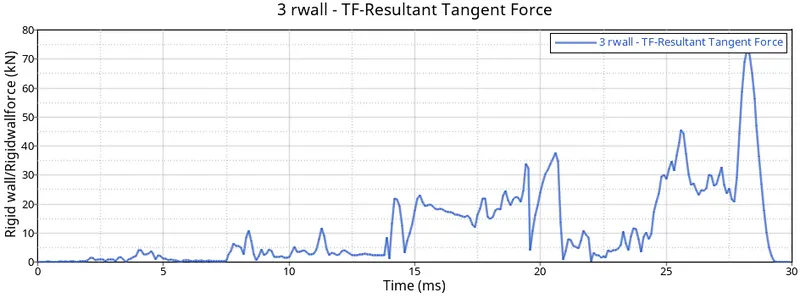
5.The maximum stress obtained is 67.51N/mm2.
6.The internal energy is increasing at the begininning because it is attached to rigid wall and it deforms smoothly at notch area where there is less stiffness.
7. The KE is varying at beginning and then it remains constant.
8.The contact energy is varying slowly at beginning and suddenly it is rised due tolarge energy due to deformation at the end.
9.The overall elements are becoming compressed and Rigid wall forces are 75kn
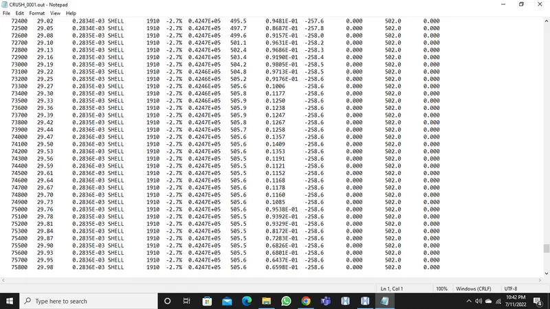
10.We can see that the energy error is -2.7% and mass error is 0% which is highly acceptable
CASE05:
1.Create a new notch in the middle ,select the whole section and run.
2.To create a notch in the middle use the translate option and translate the node to 3mm magnitude.
3.The notch is created as follows.
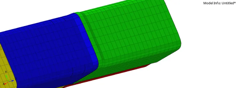
4.Follow the previous steps to run the simulation and then view the results.
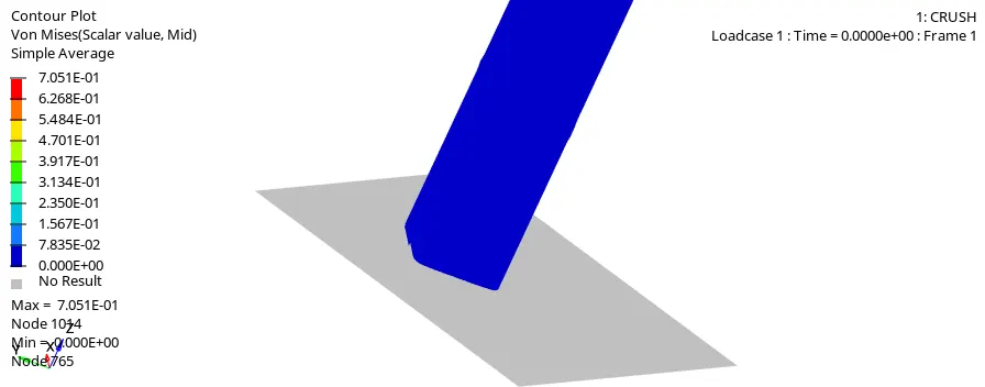
5.Plot the graphs as shown below.
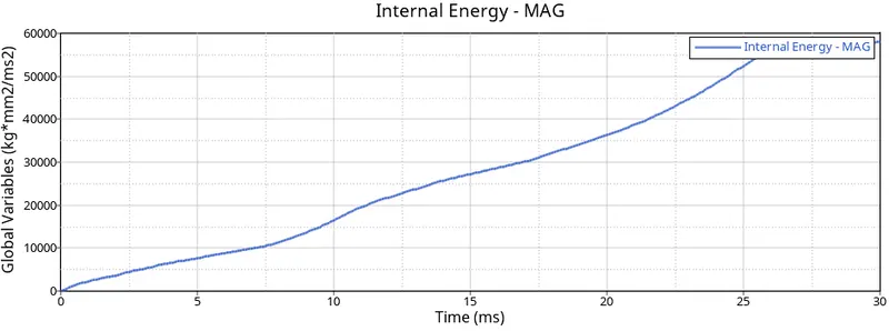
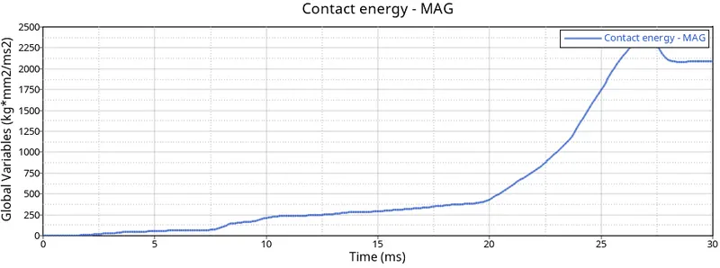
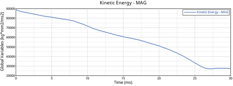
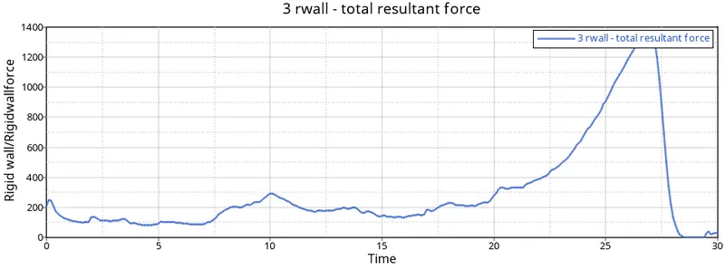
6.The internal energy is increasing at the begininning because it is attached to rigid wall and it deforms smoothly at notch area where there is less stiffness.
7. The KE is varying at beginning and then it remains constant.
8.The contact energy is varying slowly at beginning and suddenly it is rised due tolarge energy due to deformation at the end.
9.The overall elements are becoming deformed and Rigid wall forces are 1400kn
10.We can see that the energy error is -2.7% and mass error is 0% which is highly acceptable
11.The maximum stress obtained is 70.01N/mm2.
12Firstly defomation is in the middle area where notch is present
CASE5Create a new notch with nodes only from opposing 2 faces and run.
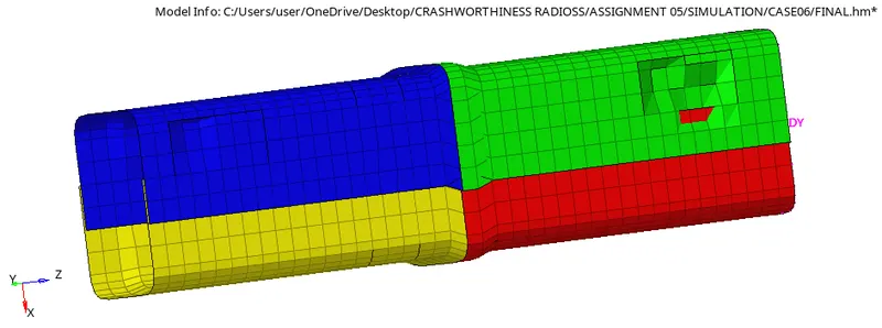
1.create a notch in the opposte facesuse the translate option and translate the node to 3mm magnitude.
3.The notch is created as follows.
3.
3.Follow the previous steps to run the simulation and then view the results.
4.
.4.Follow the previous steps to run the simulation and then view the results.
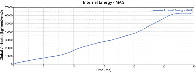
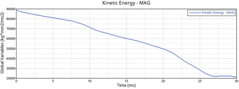
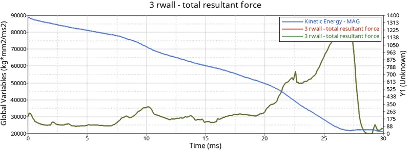
5. The internal energy is increasing at the begininning because it is attached to rigid wall and it deforms smoothly at notch area where there is less stiffness.
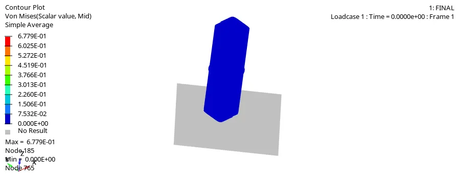
6.The more deformation takes place at the notches and all the elements are deformed in that area.
7. The KE is varying at beginning and then it remains constant.
8.The contact energy is varying slowly at beginning and suddenly it is rised due tolarge energy due to deformation at the end.
9.The overall elements are becoming deformed and Rigid wall forces are 1400kn
10.We can see that the energy error is -2.7% and mass error is 0% which is highly acceptable
11.The maximum stress obtained is 67.7N/mm2.
12Firstly defomation is in theopposite faces where notch is present and elements faced each other
CONCLUSION:The given component meshed in all 7cases. and simulation is carried out