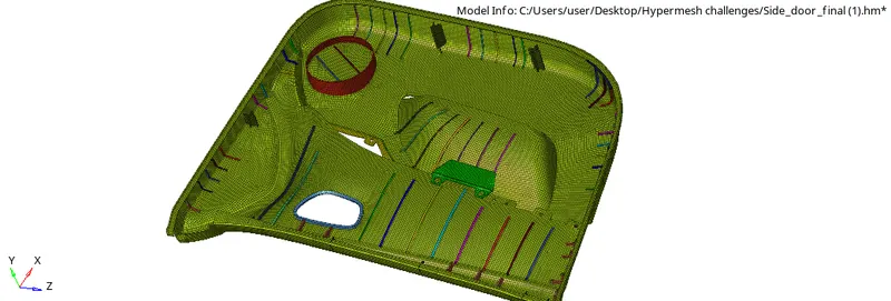
Week 12:Project-1-Meshing of Door Inner Panel Challenge
AIM: Follow the Quality Criteria and mesh the following component and assign thickness:
Target Element Length = 4 Units
| S.N | Quality Criteria | Value |
| 1 | Aspect Ratio | 5 |
| 2 | Skewness | 45 |
| 3 | Warping | 15 |
| 4 | Taper | 0.5 |
| 5 | Min. Length | 2 Units |
| 6 | Max. Length | 6 Units |
| 7 | Min angle Quad | 45 |
| 8 | Max angle Quad | 135 |
| 9 | Min angle Tria | 20 |
| 10 | Max angle Tria | 120 |
| 10 | Tria % | 10 |
THEORY:
Door panels serve as an interface between the interior of the car and the inner workings of the door, and between vehicle occupants and the door. They are expected to meet a variety of design specifications regarding safety, aesthetics, and functionality. In addition, they are expected to continue the material theme of the dashboard and pillars while concealing intricate electrical and mechanical components for operating locks, windows, and other features. The door panel has evolved from a simple two-part system of latch and simple winding mechanism to a more sophisticated enclosure. Doors currently have an inner full-width panel consisting of electronic windows, central locking system, and speakers. These panels typically consist of a foamed core covered with either textiles or plastics.
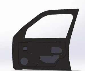
Door panels are expected to meet one of the toughest sets of requirements among interior car components. These panels should be designed to withstand and channel loads into the body of the car while being thin (<2 mm). These loads could be horizontal and vertical in nature, like the force applied on opening or closing doors while leaning/resting on them or when stepping on the armrest to access the roof An additional consideration is their ability to protect occupants from injury during a side collision, where most injuries are inflicted on the chest and pelvis as a result of crushing force of the door
Conventionally, door panels consisted of polyvinyl chloride (PVC) or foamed core with appropriate textile fabric coverings. Subsequently, there was a shift toward thin-wall moldings of ABS or PP backed by textiles in order to manufacture a contour-backed panel with recesses. This is primarily because integrated injection-molded door panel assemblies reduce the need for other energy-absorbing materials, resulting in cost reduction for manufacturers due to simplification of door construction. Currently honeycomb-based plastics are attracting attention due to their tougher, lighter, and better acoustic properties.
CAD MODEL IMAGE
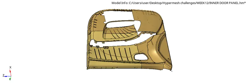
STEP1:Import the model into the hypermesh graphical area using the import option
STEP2:Check for geometry cleanup,defeature sharp corners,triplecons,freeedges and clean the geometry to obtain proper mesh
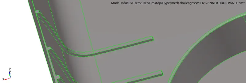
STEP3:The midsurface is to be created for shell meshing,To do this first check for component thickness by using distance option.
STEP4:As it is a plastic component,thickness will be varied, so we need to measure the distance of different surfaces and offset them accordingly.
STEP5: To create the midsurface for ribs use the midline option select two lines and create and project it to the mid surface and then create a surface.
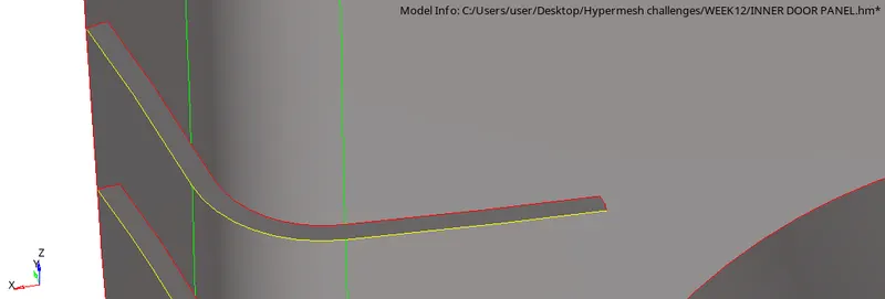
STEP6:In the same way make midsurface for different ribs and make sure they are extended to the surface.
STEP7: Using the offset option in surface edit panel,offset the base surface to half the thickness by specifying the vector normals.
STEP8: Make sure the components are stored in different collectors as per the thickness.
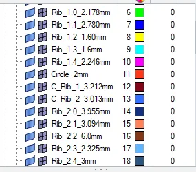
STEP9:Before proceeding for meshing,proper geometry cleanup is done and then meshing is started.
STEP10: Set the required quality criteria in the criteria panel and then proceed for meshing with the target element size.
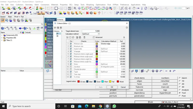
STEP11: Next,start meshing by using the automesh option in 2d panel, from the critical region
STEP12:Check for element quality criteria as given in the question.
STEP13: If any element is failing using the quality index option try to fix them
.STEP14: Make sure all the elements are passed for the criteria given.
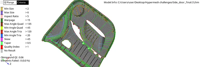
STEP15:Next,check for edges in the model by using Tool-edges.
STEP16:Make sure there is proper connectivity between the elements.
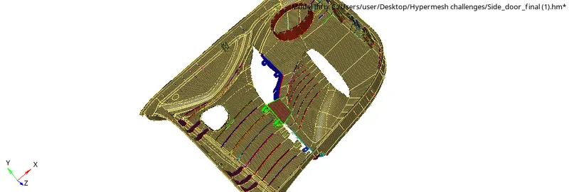
STEP17: Check for normals and try to adjust them if there are any errors.
STEP18:Next step is to assign thickness,create a property and enter the value for thickness in the property and assign the property to the midsurface
STEP19:Check for the assigned property by 2d detailed representation.
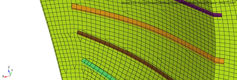
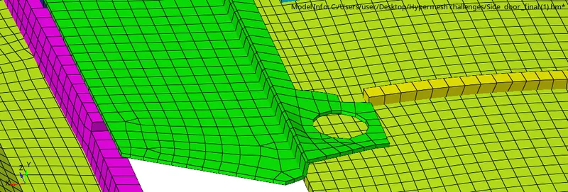
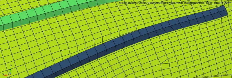
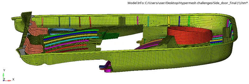
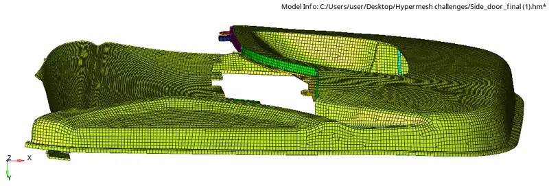
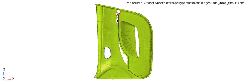
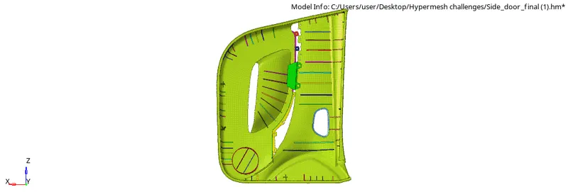
CONCLUSION.The model is meshed and thickness are assigned and quality criteria is achieved.