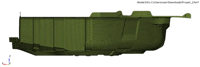
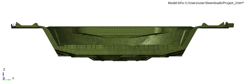
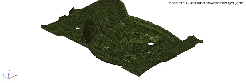
Week 12:Project 2-Meshing of Rear Wheel Holder challenge
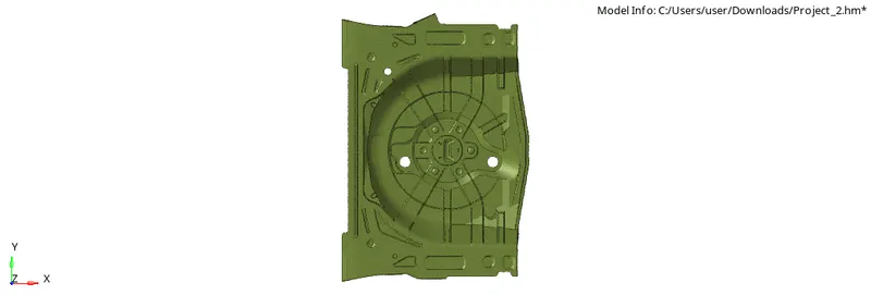
OBJECTIVE: Follow the below-mentioned quality criteria, mesh the component given below and assign thickness:
Target Element Length = 5 Units
| S.N | Quality Criteria | Value |
| 1 | Aspect Ratio | 5 |
| 2 | Skewness | 45 |
| 3 | Warping | 15 |
| 4 | Taper | 0.5 |
| 5 | Min. Length | 2 Units |
| 6 | Max. Length | 8 Units |
| 7 | Min angle Quad | 45 |
| 8 | Max angle Quad | 135 |
| 9 | Min angle Tria | 20 |
| 10 | Max angle Tria | 120 |
| 10 | Tria % | 10 |
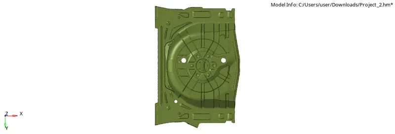
CAD MODEL IMAGE
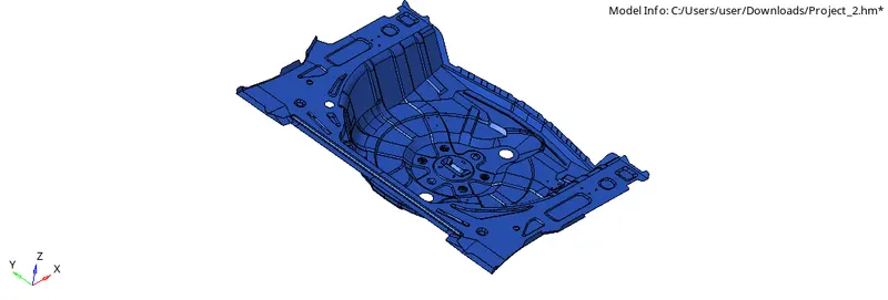
PROCEDURE:
STEP1:Import the model into the hypermesh graphical area using the import option
STEP2:Check for geometry cleanup,defeature sharp corners,triplecons,freeedges and clean the geometry to obtain proper mesh.
STEP3:The midsurface is to be created for shell meshing,To do this first check for component thickness by using distance option.
STEP4: Using the offset option in surface edit panel,offset the top surface to half the thickness by specifying the vector normals.
STEP5: Also,we can opt for auto mid surface as it is a sheetmetal component with uniform thickness.
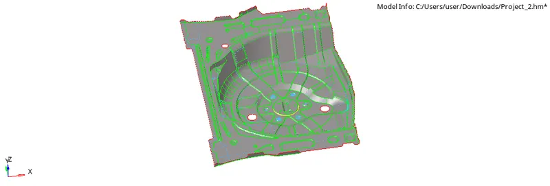
STEP6: Next,start meshing by using the automesh option in 2d panel, from the critical region in the centre,mesh towards the outer side for a proper mesh flow,
STEP7:Check for element quality criteria as given in the question.
STEP8: If any element is failing using the quality index option try to fix them
.STEP9: Make sure all the elements are passed for the criteria given.
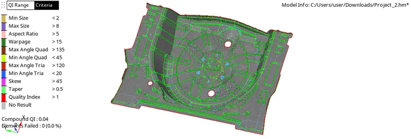
STEP10:Next,check for edges in the model by using Tool-edges.
STEP11:Make sure there is proper connectivity between the elements.
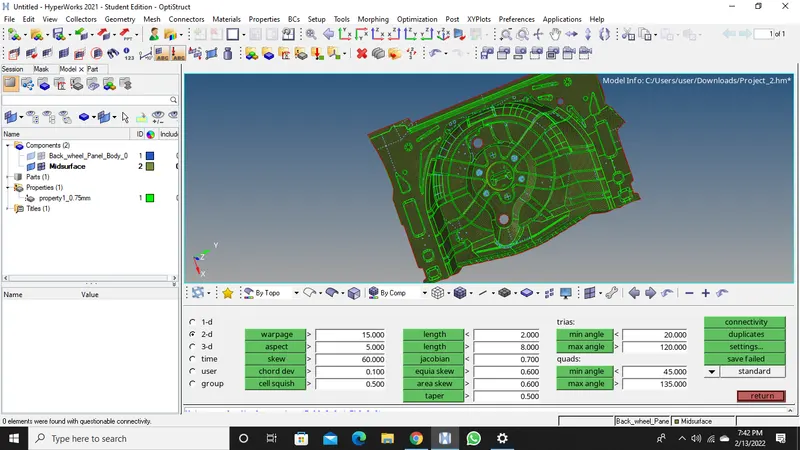
STEP12: Check for normals and try to adjust them if there are any errors.
STEP13:Next step is to assign thickness,create a property and enter the value for thickness in the property and assign the property to the midsurface
STEP14:Check for the assigned property by 2d detailed representation.
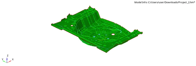
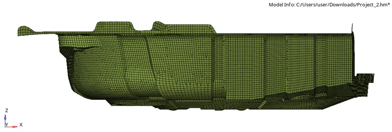
CONCLUSION:The model is meshed for the following criteria and thickness is assigned
 '
'