Assignment 1
Aim: To explore the GUI of GT suite and note down the settings of the intercooler tutorial.
Objective:
1) To list down modules available with brief descroption.
2) To list down the following settings.
Time control flag, Time step and control solution, Integrator/Solver type.
3) To explore the intercooler tutorial and note down the following setting.
Run setup, Advanced setup, Plot setup, Output setup.
4) To run the intercooler tutorial and solve the problem using following initial condition.
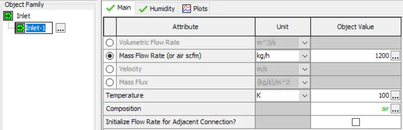
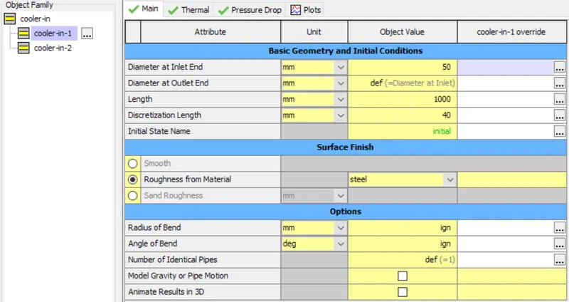
- Diameter of cooler inlet and outlet pipe= 50 mm
- Length of the CAC= 1000 mm
- Inlet mass flow rate = 1200 kg/ h at 100 degC
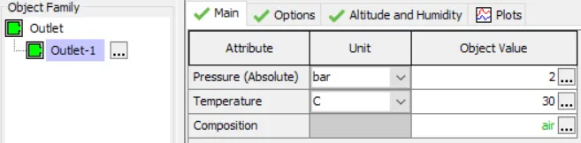
- Outlet pressure 2 bar at 30 deg C
Introduction:
The GT suite is used by most leading OEM's and suppliers. This simulation tool with leading capabilities and libraries is aimed at providing detailed system analysis or sub-system/component analysis, design optimization, root cause investigation.
Modules available:
Flow: This model contains the solution for Navier-Stokes equations, namely the conservation of continuity, momentum and energy equations. The flow model is further expanded into following parts,
- Components: This section contains the objets involed in the simulation. Ex:- inlet, outlet, engine cylinder and pipe.
- Connection: This section contains the parts that connect the objects in the simulation. Ex:- Valve connection, orifice connection.
- Reference: This section contains the parameters of simulation. Ex:- engine geometric parameters, heat transfer parameters, fluid properties.
Mechanical: This part involves the mechanical portion of the simulation.
- Components: This section contains the objets involed in the simulation. Ex:- inlet, outlet, engine cylinder and pipe.
- Connection: This section contains the parts that connect the objects in the simulation. Ex:- Valve connection, orifice connection.
- Reference: This section contains the parameters of simulation. Ex:- engine geometric parameters, heat transfer parameters, fluid properties.
Some important settings:
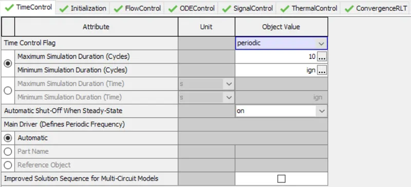
Time control:
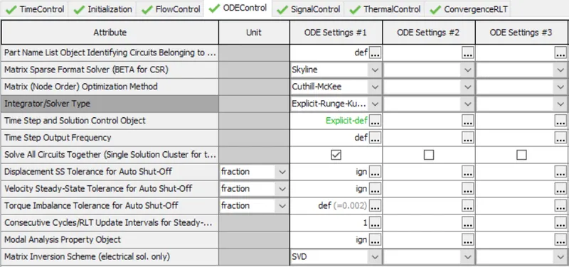
Time step and solution control:

Integrator/Solver type:
Intercooler tutorial:

Inlet condition:
Cooler inlet pipe condition:
Outlet condition:
Run case setup:
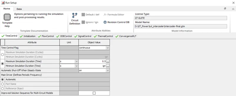
Time control: This template is used to define the simulation run time/simulation duration and time controlling variables.
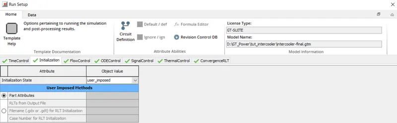
initialization: This template defines how the initial conditions are imposed for the simulation.
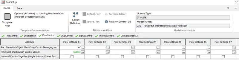
Flow control: This template is used to specify the flow parameters in the circuits and solver settings related to modeling of flow for the circuits.
ODE control: This template is used to define the solver settings related to independant ODE circuits. An ODE circuits consists of interconnected group of mechanical, electrical, magnetic or control parts.
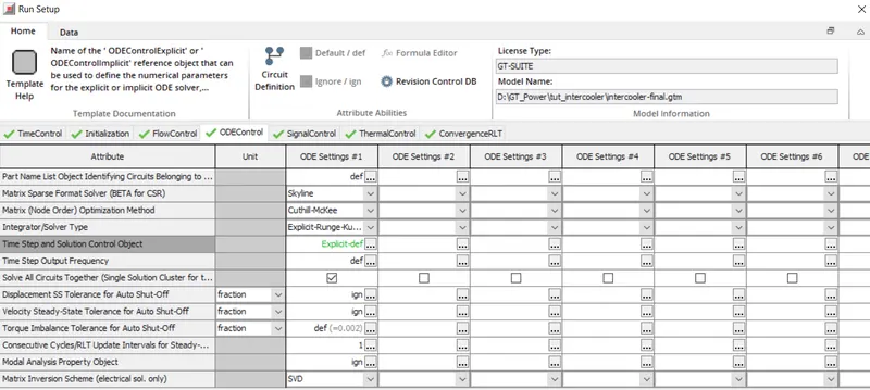
The thermal control template defines the thermal wall solver settings and convergenceRLT defines the convergence criteria for the simulation.
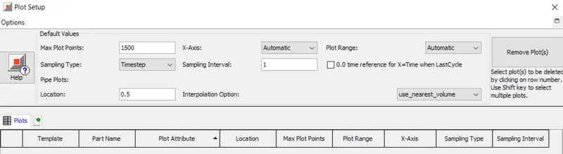
Plot setup: The plot setup helps in setting up plot storage, plot locations.
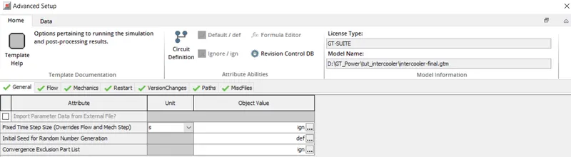
Advanced setup:
Output setup:
Data Storage: This template is used to suppress certain outputs in GT-Suite which are not desired for simulation. Thus helps in computation efficiency.
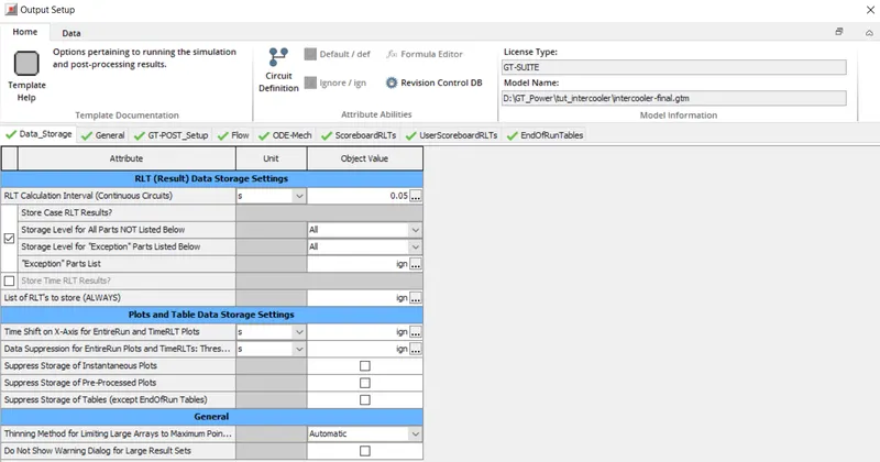
General:This template is used to specify the time step for plots and legends for plots and monitoring RAM.
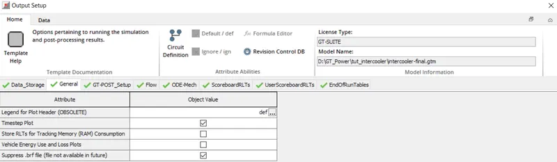
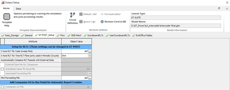
GT-Post setup: This template is used to define the settings for GT-Post before simulation.
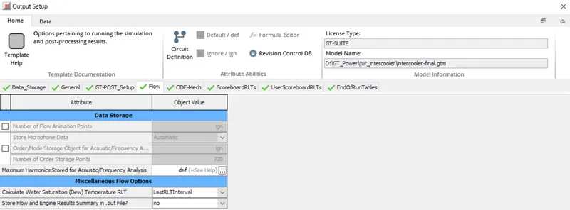
Flow: This template is used to define settings for storage of flow output variables which can be viewed after the simulation is completed.
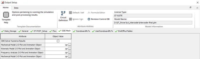
ODE-Mech: This template is used to specify the settings for storge of numerical outputs.
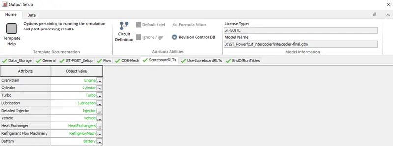
ScoreboardRLTs
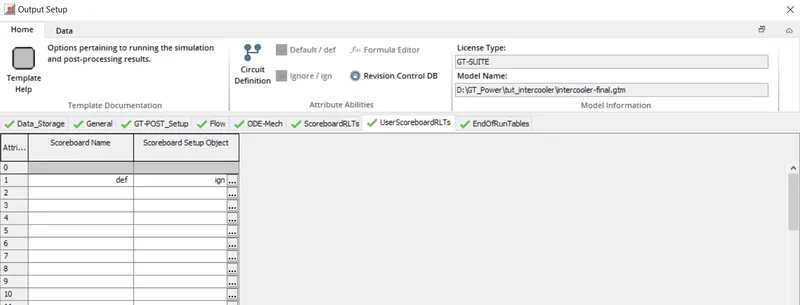
User Score board RLTs
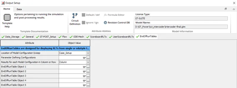
End of run tables
Results:
Average Pressure RLT contour Map

Pressure plot at cooler inlet
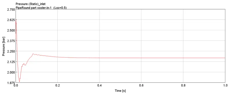
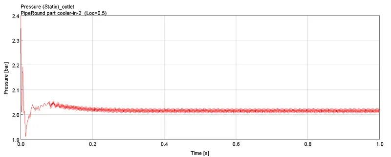
Pressure plot at cooler outlet
Net heat transfer rate RLT contour Map

From the above contours and plots obtained from the simulation,
Pressure drop across charge air cooler = Inlet pressure - Outlet pressure = 2.17-2.03 = 0.14 bar
Net heat transfer rate at charge air cooler = -82.7 KW