Parametric study of gate valve
Aim: To perform parametric study on gate valve model using ANSYS fluent.
Objective:
1) To set gate disc lift distance as input parameter and to set mass flow rate as output parameter.
2) To calculate the flow coefficient and flow factor by increasing the lift of gate disc from 10% to 80%.
Geometric model of gate valve :
The gate valve model is designed in design softwares like CATIA or Solidworks and is imported to spaceclaim for the simulation. The gate valves are the device which is primarily designed to start or stop the flow.
Extracted fluid volume of gate valve :
Mesh :
Total number of elements = 4,42,263
Element size = 5.8 mm.
Case setup :
Inlet boundary condition(pressure inlet)
Pressure = 10 Pa
Gravity
Enabled = -9.81 m/s^2 (Z-axis)
Material
Water is added to the volume extracted
Initialization
Standard initialization and initial conditions computed from inlet boundary condition.
Viscous model
K-epsilon model with scalable wall function
The case setup and mesh generated remains same for all the four cases. The pressure inlet boundary condition is used to make the water flow from the inlet boundary to the outlet boundary. The flow from inlet to outlet is also caused due to the pressure difference. The gravity is enabled in Z-axis because of the geometric orientation of gate valve model. The K-epsilon with scalable wall function is used as the turbulence model which helps in capturing the turbulence effects near the walls and increases rate of convergence. The results obtained for different gate disc position is given and discussed below.
Case 1: lift = 12 mm
Gate disc position:
Velocity contour :
Pressure contour :
Case 2: lift = 25 mm
Gate disc position :
Velocity contour :
Pressure contour :
Case 3: lift = 45 mm
Gate disc position :
Velocity contour:
Pressure contour:
Case 4: lift = 65 mm
Gate disc position :
Velocity contour:
Pressure contour:
Parametric table
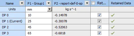
The above figure shows the parameter data. The P1 represents the parametric input of gate disc lift distance and P2 represents the parametric output of mass flow rate. The negative sign in the output parameter of mass flow rate indicates that the mass is flowing outwards. It can be seen from the above table that the mass flow rate increases as the gate disc lift distance is increased. The mass flow rate obtained from the parametric table is used for calculating flow factor and flow coefficient. The calculation for flow coefficient and flow factor is given below.
Calculation and results :
Mass flow rate :- It is defined as the mass of a substance flowing per unit time and it is given by the formula,
m = rho * Q
where m - mass flow rate ( kg/s )
rho - density of the flluid ( kg/m3 )
Q - flow rate ( m3/s )
Flow coefficient :- The flow coefficient of a device is a relative measure of its efficiency at allowing fluid flow. The flow coefficient is the volume (in gallons) of water at 60deg F that will flow per minute through a valve with a pressure drop of 1psi across valve. It is given by the formula,
Where Cv - flow coefficient
Q - volume flow rate ( gallons per minute)
SG - specific gravity of the fluid ( for water = 1 )
dP - pressure drop ( Psi )
Flow factor :- The flow factor is flow coefficient in mmetric units. It is defined as the flow rate in cubic meters per hour of water at a temperature of 16deg C with a pressure drop of 1 bar. It is given by the formula,
Where Kv - flow factor
Q - volume flow rate ( m3/hr )
SG - specific gravity of the fluid ( for water = 1 )
dP - pressure drop ( bar )
Calculation of flow coefficient for different lift of gate disc :-
Calculation of flow factor for different lift of gate disc :-
Observation:
- It is observed from contours obtained from the simulation that the mass flow rate increases and pressure drops as the gate disc of the valve is lifted higher.
- From the above table it is observed that the flow coefficient and flow factor increases as the pressure drop across the valve is lowered and the pressure drop decreases as the mass flow rate increases across the valve.
- If the valve is going to be opened most of the time, then a valve with higher flow coefficient must be selected with lower head loss and to save energy. If the valve is going to be regulated most of the time, then a valve with lower range of flow coefficients must be considered.
Conclusion:
The simulation of flow in gate valve was done using ANSYS Fluent. The gate disc position was parametrized as the input and mass flow rate (kg/s) was parametrized as the output. The flow coefficients and flow factoris calculated.