Assembly of Yacht
Design and Modelling of Sunseeker Yacht using Solidworks
Objective
1. Design of each part of the Sunseeker Yacht as per the blueprint using Solidworks software.
2. Assemble the different parts of the Yacht using appropriate mates.
3. Developing photorealistic view of the Yacht using Solidworks Visualise software and photoview 360.
Introduction
A yacht is a sailor power vessel used for sports or pleasure activities. Originally, all yachts were made of wood, using a wooden keel and ribs, clad with planks. These materials were supplanted with iron or steel in steam yachts. In the 1960s fiberglass became a prevalent material. These materials and others continue in use.
In this project the model of yacht is made with the help of the blueprint using surface modelling and solid modelling technique.
Surface Modelling:-
Surface modelling is usually used in computer aided design applications. In this users can look at specific objects at specific angles with solid surfaces. There are various features present in surface modelling which are used in this project in order to build different parts.
Solid Modelling:-
Solid modelling is generally used in computer aided design applications in order to give specific shape to an object to give the object 3D look.
In this project step by step procedure is used to build the yacht by first doing surface modelling of each part and then converting them into a solid model with appropriate dimensions and then giving the parts appropriate shape using solid modelling technique. At the end each part is bought in the assembly environment and then the parts are assembled together in order to build the Sunseeker Yacht.
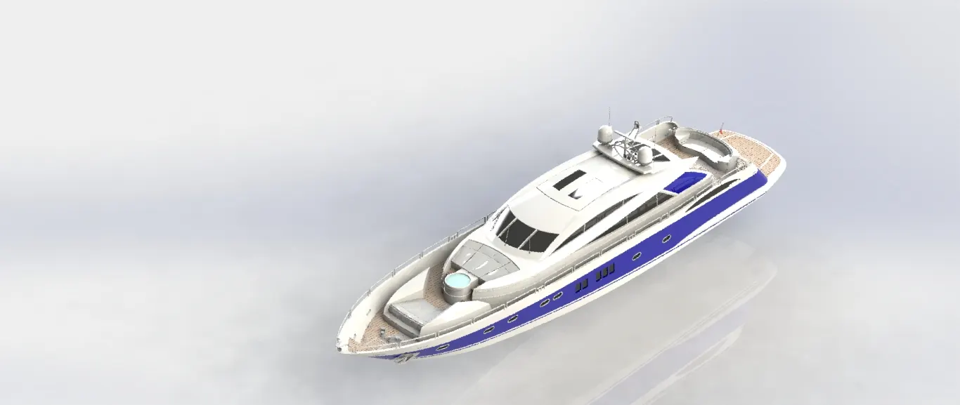
The different parts of the yacht that are modelled in this project are:-
1. Propeller
2. Radar
3. Hull
4. Garage Door
5. Front Seat
6. Middle Seat
7. Rear Seat
8. Superstructure
9. Radarmast
Part Modelling
1. Propeller
Propeller is used as a driving unit in a yacht, it's main purpose is to convert the rotational motion of the blades into linear thrust which is connected to the engine and generates energy to run the yacht.
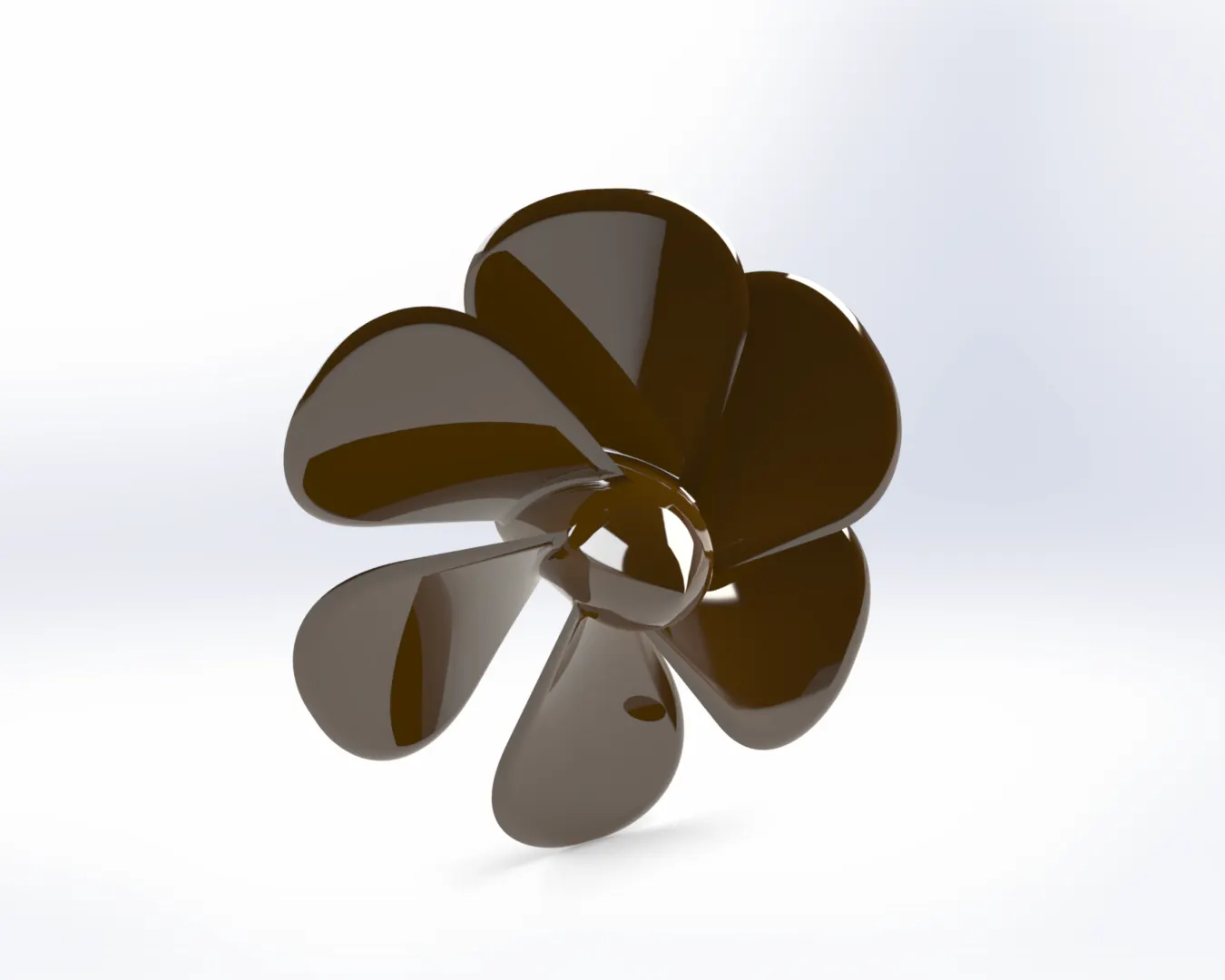
Features used to make above part
1. Revolve
2. Cut Extrude
3. Surface Loft
4. Fillet
5. Circular Pattern
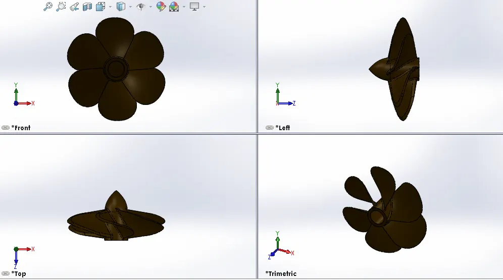
Procedure used to make propeller:-
- The propeller base is made first using proper sketch and then revolve feature is used to give desired rounded shape.
- Blades are mounted on the base which is made using surface loft feature.
- After this desired shape is given to all parts using various other features like fillets, cut extrude and circular pattern.
- When the part was designed completely, proper appearance is given to it.
2. Radar
Marine radar is a device used in ships for the purpose of carrying out safe navigation. The radar is used in identifying, tracking and positioning vessels so as to safely navigate a ship from place to another.
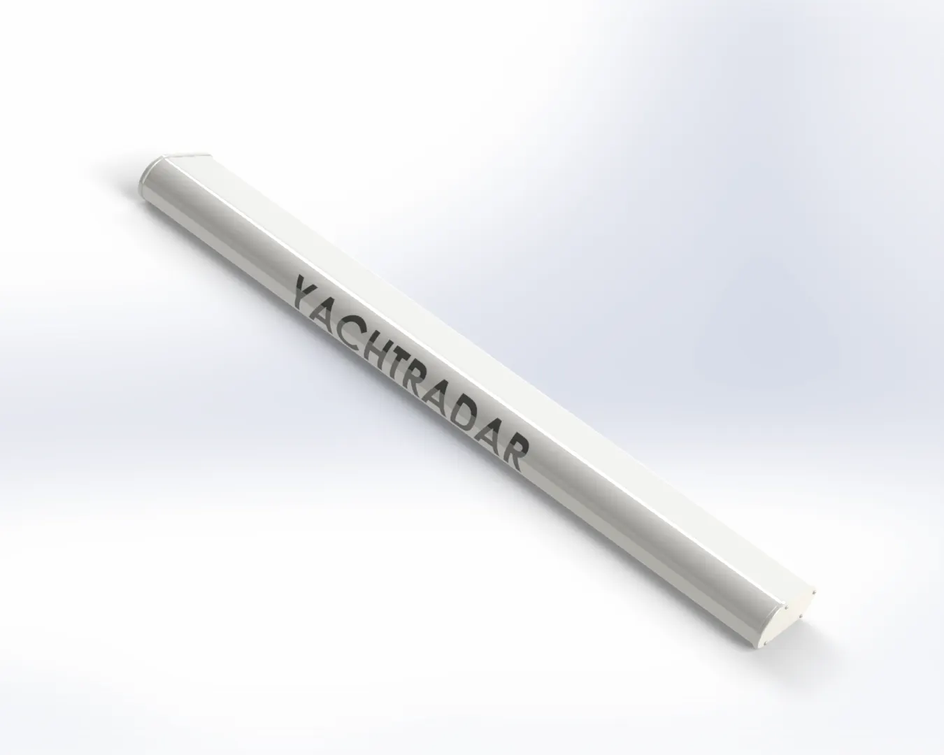
Features used to make the above part:
1. Boss Extrude
2. Fillet
3. Cut Extrude
4. Mirror
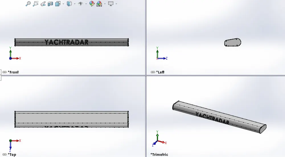
Procedure used to make Radar:-
- The sketch of the part is made using various sketch tools like lines, rectangles and then constraints were defined.
- The 2D sketch is then converted into 3D using features like boss extrude, cut extrude etc.
- Desired shape is given to the part by applying fillets and then text was written on this part.
3. Hull
Hull is most important as well as the most noticeable part of a ship. It protects the cargo and the machinery of the ship. It can also protect the boat from flooding and other structural damage. It is the part of the vessel which meets the ocean.
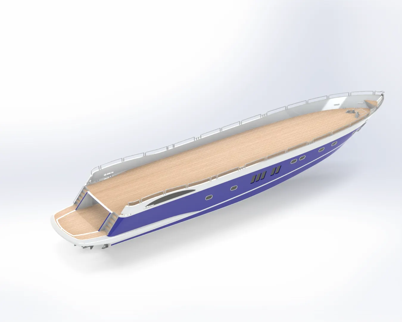
Features used to make above part:-
1. Curves
2. Surface Loft
3. Surface Trim
4. Surface Fill
5. Surface Knit
6. Shell
7. Boss Extrude
8. Cut Extrude
9. Fillet
10. Chamfer
11. Sweep
12. Dome
13. Linear pattern, etc.
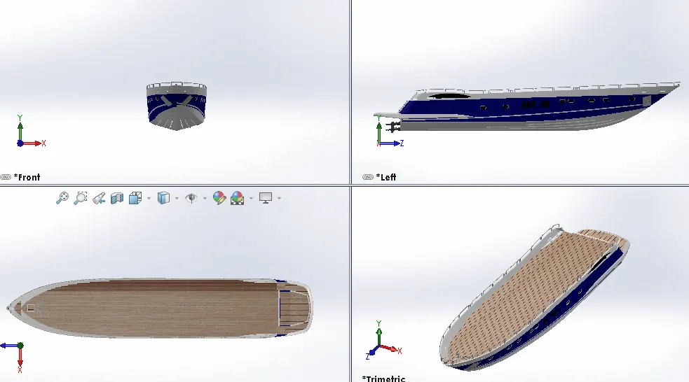
Procedure used to make Hull:-
- First, the blueprint is inserted in the work space and then by considering each shape of the Hull sketches were drawn in different views in order to give the sketch desired shape.
- Step by step when the sketch was complete by fully defining it, surface modelling technique was used to give an outer look to the base of the Hull using surface modelling features like Surface Loft, Surface Trim, Extend Surface, Surface Fill, etc.
- Railings were then designed and mounted on the edges by making proper sketches and then sweep feature was used to give rounded shape to the railing.
- When the complete base was modelled it was then converted into a solid model using the create solid feature in Surface knit.
- When half of the Hull was designed, mirror feature was used to model the complete structure of the Hull.
- When the design was complete proper decals and appearance was given to Hull.
4. Garage Door
Garage Door is used to cover the vehicle that would be kept in the yacht so that it does not displace while the vehicle is placed in the yacht while it is sailing.
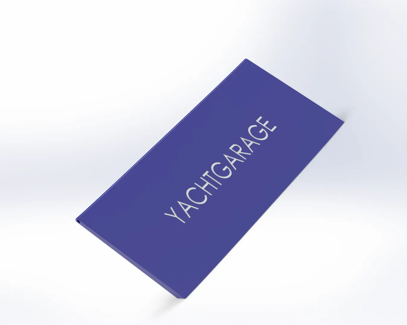
Features used to make the above part:-
1. Cut Extrude
2. Shell
3. Fillet
4. Mirror
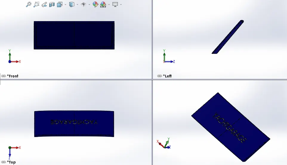
Procedure used to make Garage Door
- The solid space that was cut from the hull for placing the vehicle is bought in the workspace in order to make the garage door.
- Then the unwanted material was removed using cut extrude feature.
- After this proper design was given to this using shell and cut extrude feature.
- After completion of the part, proper appearance was given to the garage door.
5. Front Seat
Front Seat is placed on the front portion of the yacht, where the passenger can rest upon.
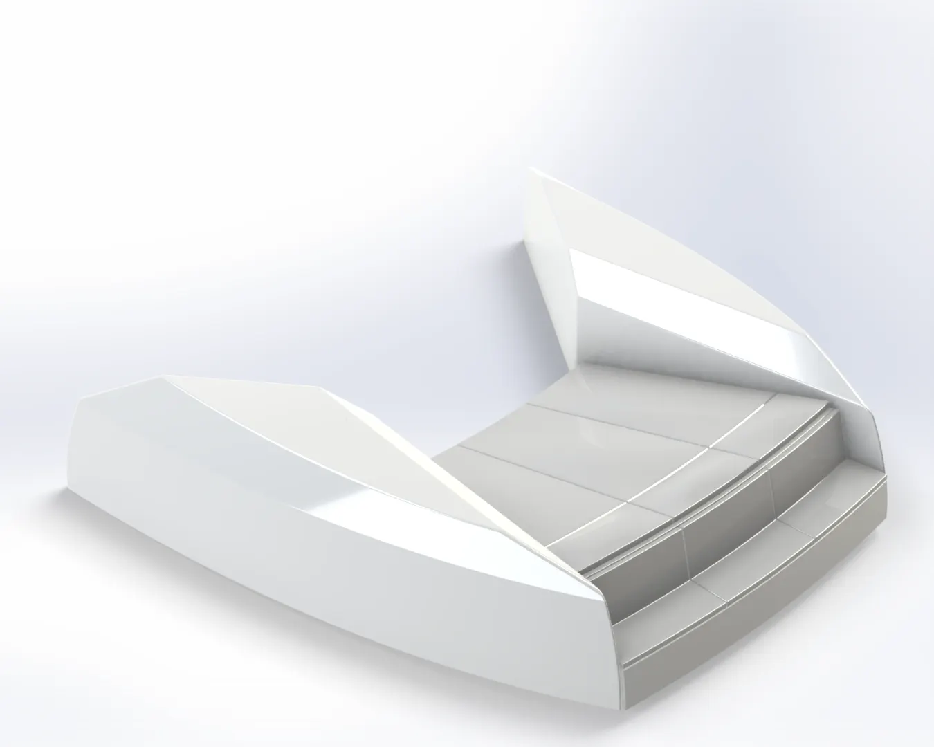
Features used to make above component:-
1. Surface Sweep
2. Surface Trim
3. Surface Loft
4. Surface Fill
5. Surface Knit
6. Revolve
7. Chamfer
8. Cut Extrude
9. Mirror
10. Dome
11. Fillet
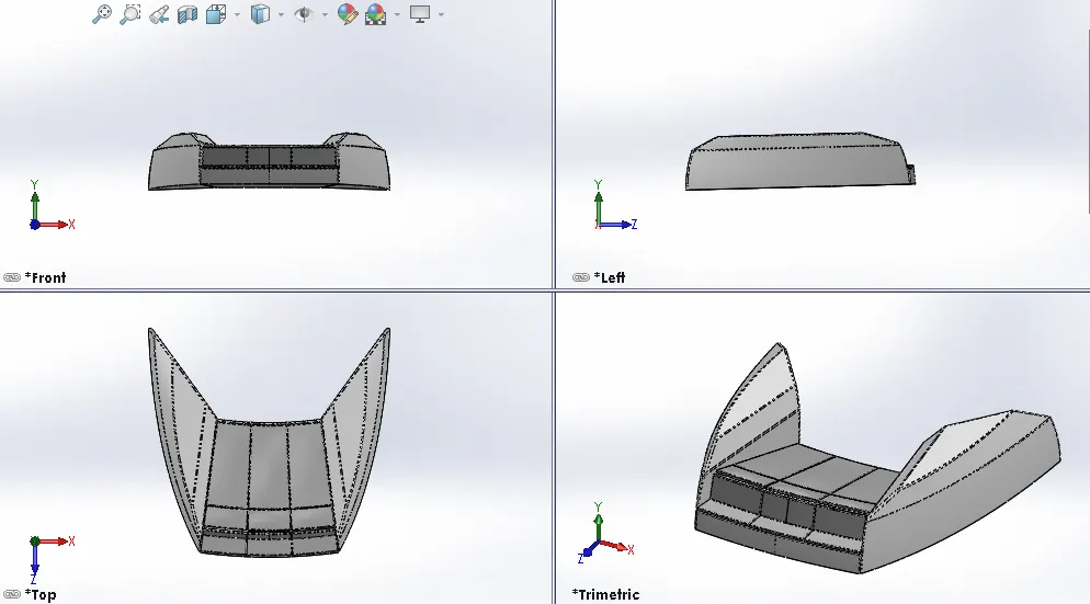
Procedure used to make Front Seat:-
- First, the blueprint of the yacht is inserted in the workplace along with the deck surface of the hull.
- The front seat is designed using sketch tools at appropriate position with the help of deck surface and proper dimensioning.
- Desired shape is given to the seat using the blueprint and various features of surface modelling, fillet, chamfer, mirror, etc.
- Appearance is given to the front seat after modelling of the seat is complete.
6. Middle Seat
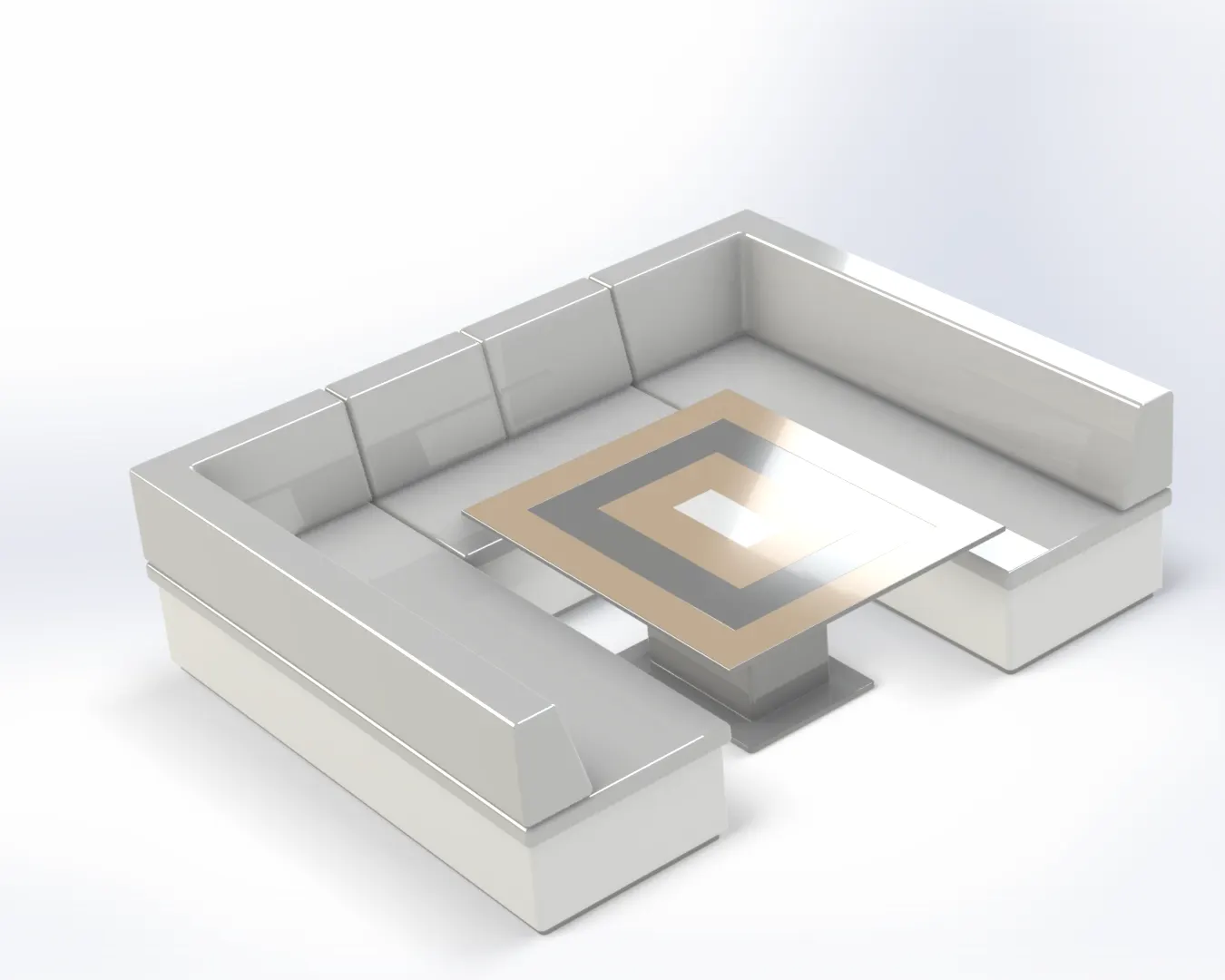
Features used to make above component:-
1. Boss Extrude
2. Chamfer
3. Fillet
4. Mirror
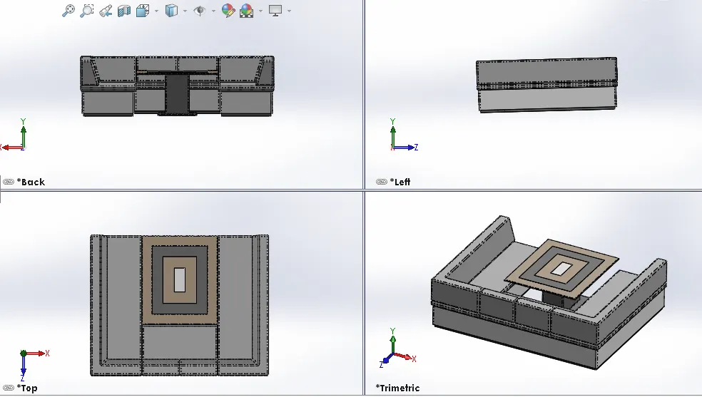
Procedure used to make Middle Seat
- The blueprint and the surface of the deck is first inserted in the workplace.
- The sketch of the middle seat is made with proper dimensioning and placing it at appropriate position.
- Desired shape is given to the part with the help of features like boss extrude, fillet, chamfer and mirror.
- Proper appearance is given to the middle seat after completion of design.
7. Rear Seat
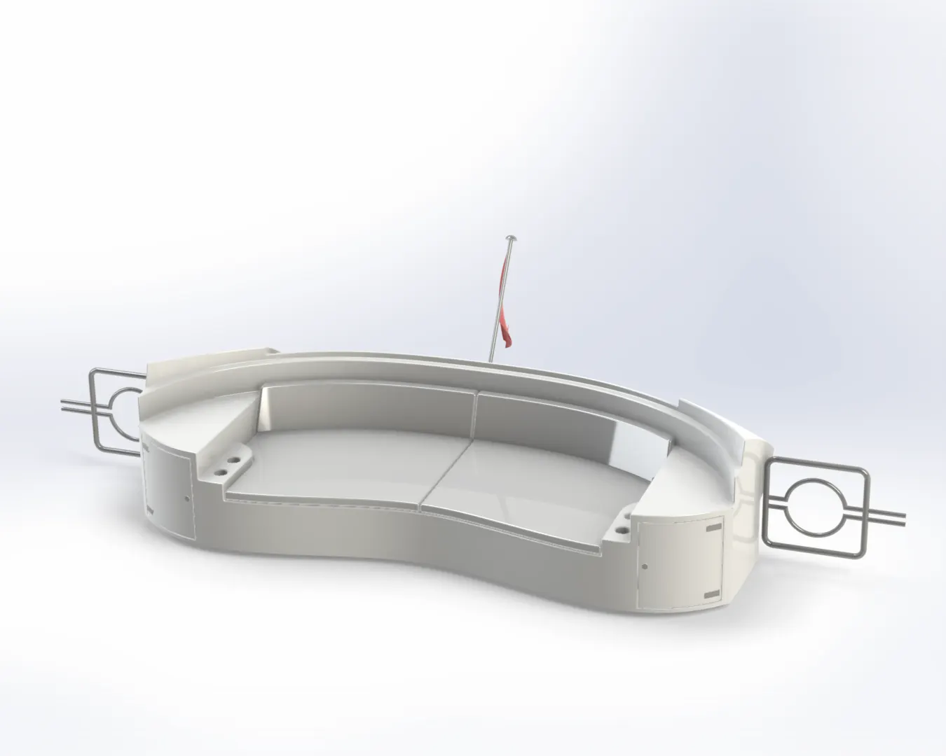
Features used to make above part:-
1. Surface Sweep
2. Surface Offset
3. Surface trim
4. Surface Knit
5. Surface Extend
6. Boss Extrude
7. Fillet
8. Chamfer
9. Cut Extrude
10. Sweep
11. Mirror, etc.
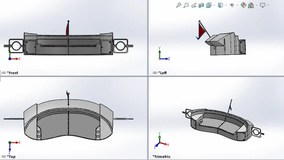
Procedure used to make Rear Seat
- The Blueprint and the surface of the deck is first inserted in the work space.
- The sketch of the rear seat is made one by one using sketch tools like line, spline, 3D sketch, rectangle, etc with proper dimensioning.
- Desired shape is given to the seat with the help of surface modelling features and then converting this into a solid model.
- Proper appearance is given to the rear seat after completion of the model.
8. Superstructure
Superstructure is the additional portion of the yacht which is built above the surface of the deck which can be used for various purposes. The size of the superstructure has a great influence on the mobility of the vessels. They are designed in a manner, so that they add value and hinder the speed and mobility in the least. The superstructure is mostly designed in fashion as well. This is because it is the most easily visible part of the ship, in fact it is the identification of the ship, and so the designers try to provide it with the identity that is unique.
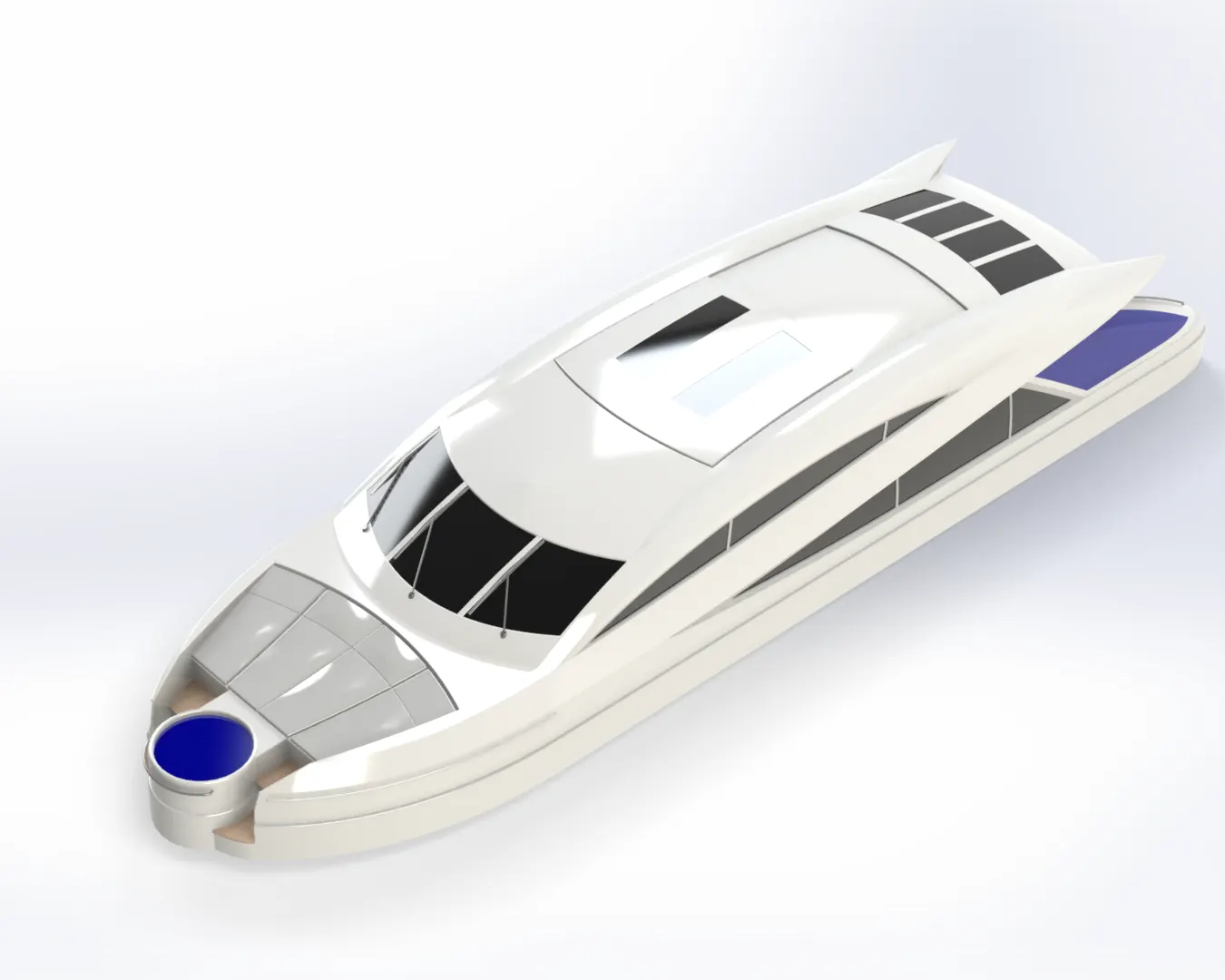
Features used to make above part:-
1. Surface Extrude
2. Surface Loft
3. Surface Sweep
4. Surface Trim
5. Fillet
6. Chamfer
7. Mirror
8. Surface Sweep
9. Projected Curves
10. Sweep
11. Cut Extrude
12. Boss Extrude, etc.
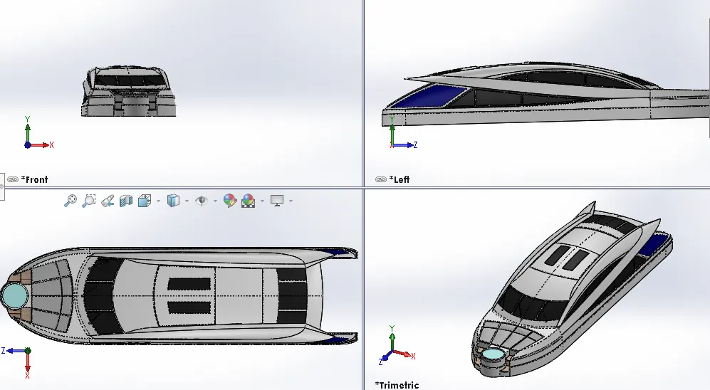
Procedure used to make Superstructure:-
- The first step in order to make the superstructure is to insert the blueprint and the surface of the deck in order to place the structure at appropriate position.
- Half portion of the part is made with the help of sketch tools like lines, rectangle, circle, arcs, spline, etc and then proper dimensioning is given to the sketch to make it fully defined.
- Projected curves feature is used in most of the cases to give desired shape to the structure.
- After completion of the sketch surface modelling features like surface loft, surface fill, surface trim etc are used to give proper outer look to the superstructure.
- After surface modelling and giving desired shape it is then converted into a solid model with the help of creating a solid feature in surface knit.
- Half of the portion is made with various other features of surface modelling, boss extrude, extrude cut, fillet, chamfer, etc and after completion of this mirror feature is used to complete the whole structure of superstructure.
- Proper appearance is given to the windows and other parts of the structure and decals were added after completion of the model.
9. Radarmast
A radarmast is a structure that is mounted on top of the superstructure in this project. On top of this the radar is mounted which is used for the navigation purpose when the boat is sailing.
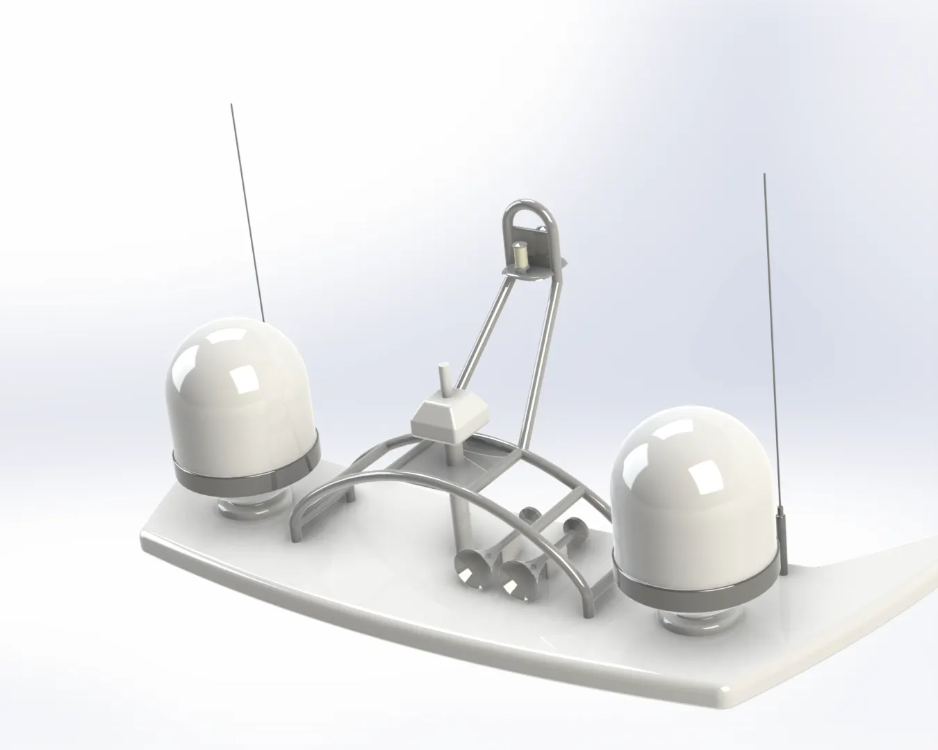
Features used to make the component:-
1. Boss Extrude
2. Fillet
3. Revolve
4. Sweep
5. Chamfer
6. Mirror
7. Dome
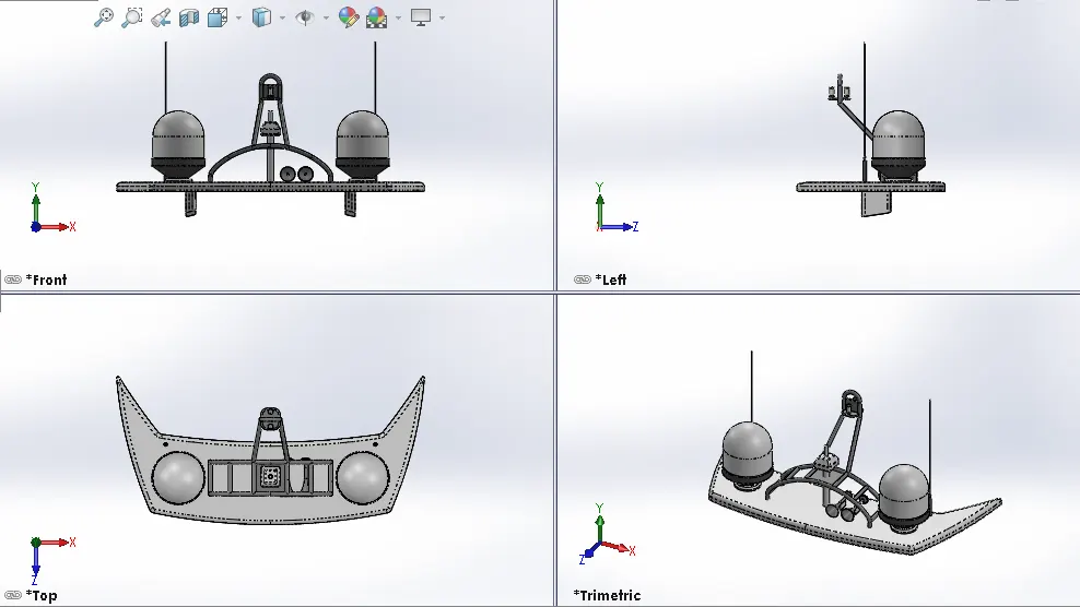
Procedure used to make Radarmast:-
- First, the blueprint of the yacht and the top surface of the superstructure where the radarmast will be positioned is inserted in the workspace.
- Proper sketch is made using sketch tools along with dimensioning it to get accurate figure.
- After completion of each sketch, it is converted into a 3D figure by using various features like boss extrude, fillets, chamfer, etc.
- Appearance is given to the radar mast after completion of it's design.
Assembly
The next step after completion of design and modelling of each part of the component is to assemble these components in one workspace and position them at accurate places in order to complete the Sunseeker yacht.
In order to place the different parts at right places, first the component was bought one by one in the workspace using the insert component feature and then mates feature was used to give proper relation to one part with respect to another with which it will attach.
Each part was bought one by one in the following manner using the insert component feature:-
| 1. | Hull |
| 2. | Superstructure |
| 3. | Radarmast |
| 4. | Front Seat |
| 5. | Middle Seat |
| 6. | Rear Seat |
| 7. | Garage Door |
| 8. | Propeller |
| 9. | Radar |
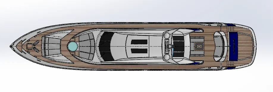
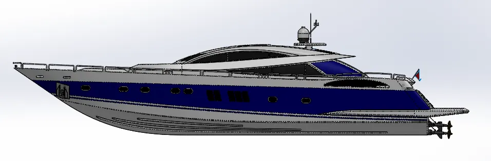
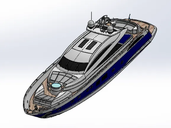
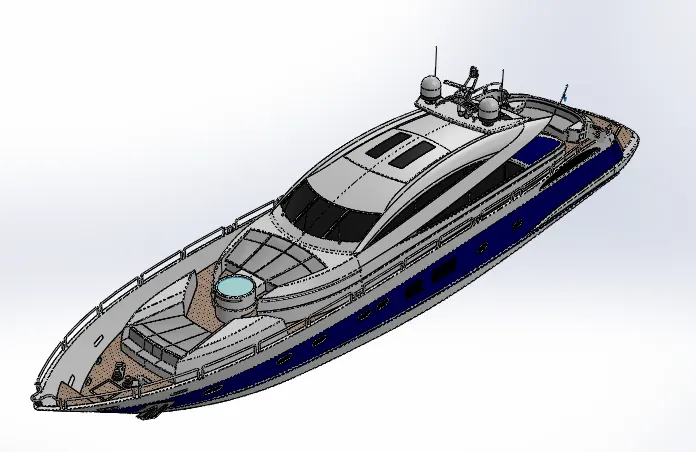
Different views of assembly of Sunseeker yacht.
1. Front view
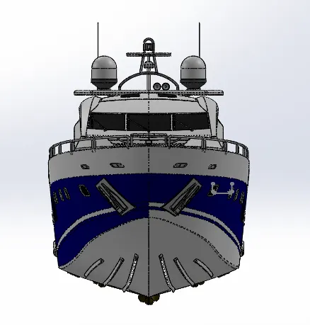
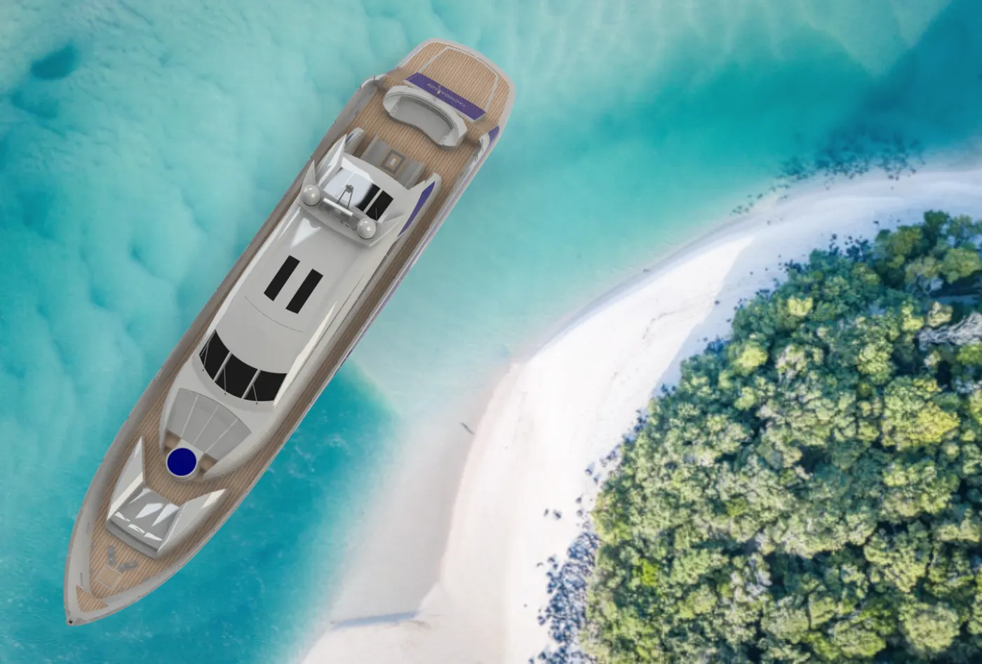
2. Top view
3. Side view
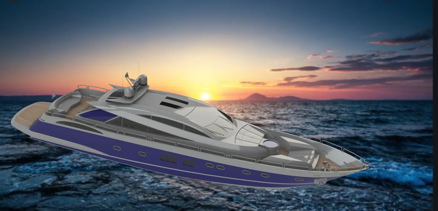
4. Isometric view
5. Camera view
Rendering
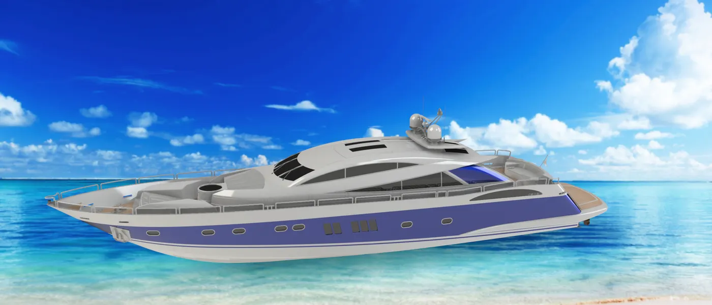
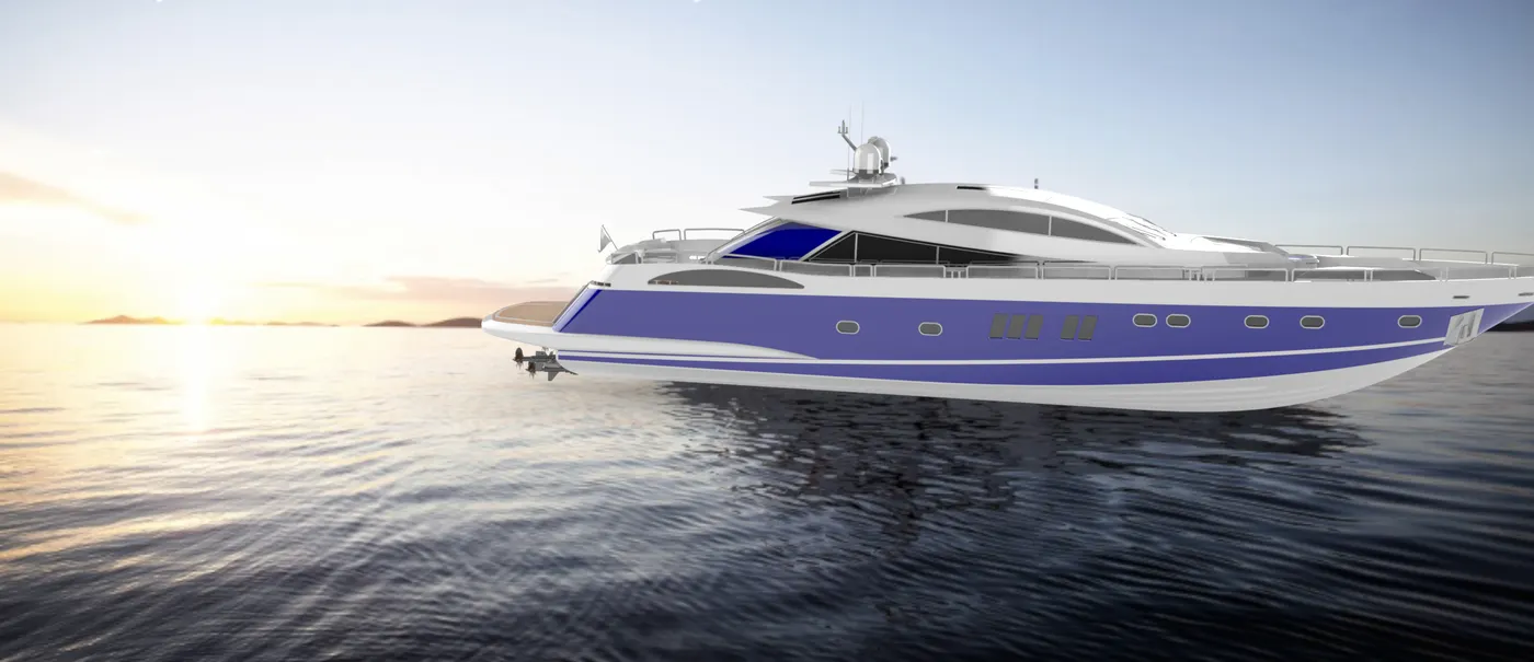
The next step in the project was to give a photo realistic view to the assembly of the yacht for the better view, for this purpose Solidworks visualization software was used.
Conclusion
1. The design of each part of the Sunseeker yacht was modelled with proper dimensioning using Solidworks software.
2. All parts were assembled together and placed at appropriate positions to complete the assembly.
3. Photorealistic view was given to the yacht scene using Solidworks visualization and photoview 360.