Advanced Sheet Metal Design Using NX Cad Challenge_7_ Metal bracket-II
SHEET METAL BRACKET II DESIGN USING NX
OBIECTIVE
The aim of this project to design a metal bracket and create a detailed drawing for manufacture using Siemens NX sheet metal Application
INTRODUCTION
Sheet metal is defined us the thin sheet which made by alloys according to needed parameters Those sheets are undergoes bending forming, cutting, enclosing etc.
Sheet metal usage is increasing every day to life including kitchen appliances to rocket spacing every its used to fabrication of surfaces in every industries. Thin sheet metals are also known as coils and foils.
Design Approach /Methodology
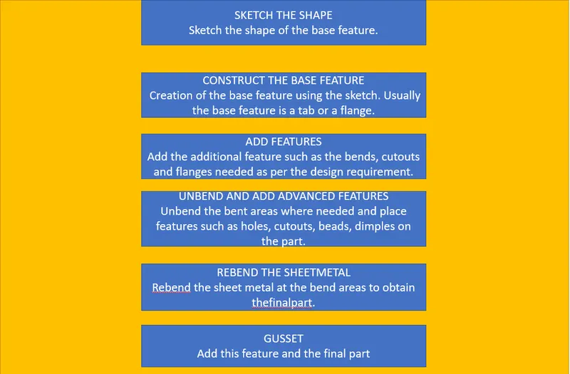
DESIGN FEATURES:
The following features are used in the project. This project was designed in the sheet metal module of the Siemens NX CAD.
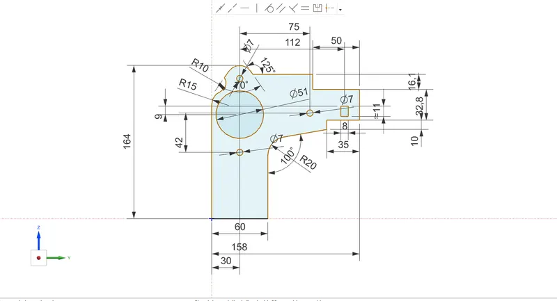
SKETCH-This command is used the draw the shape of the design.
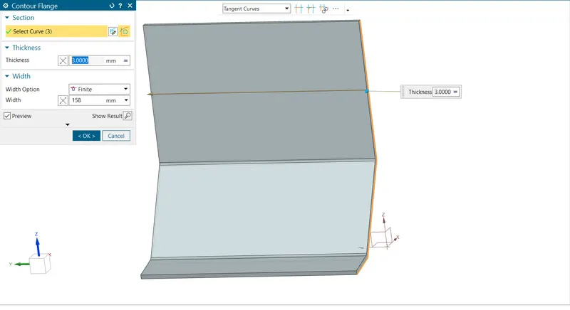
CONTOUR FLANGE-This command is used to create the base feature by extruding the sketch along a vector. Here the sketch is extruded to
158mm long.
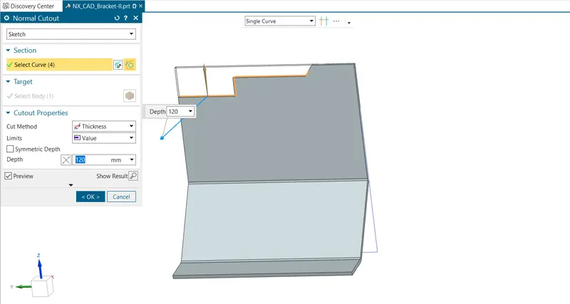
NORMAL CUTOUT- This command is used to create a cutout by projecting a sketch onto the model and then cutting perpendicular to the face intersected by the projection.
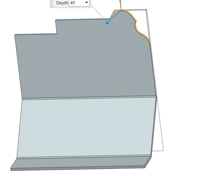
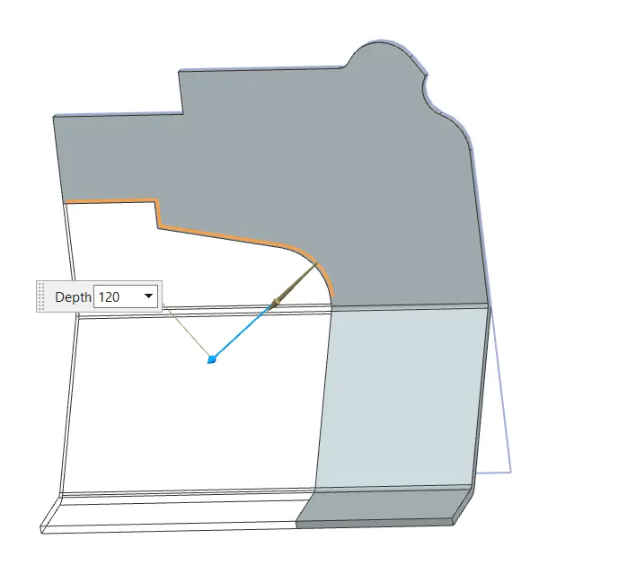
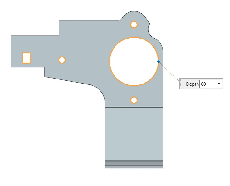
BREAK CORNER- This command is used to round the edges of the flanges or tab, in this project it was used to round the edges of the
flanges.
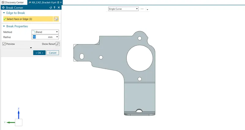
UNBEND- This command was used to unbend the bent areas in the sheet metal to get the flattened sheet metal.
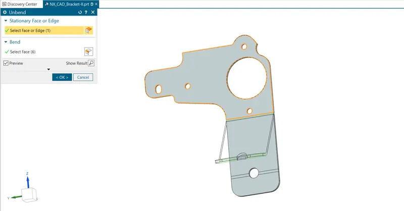
Creat a sketch and use normal cut out comand
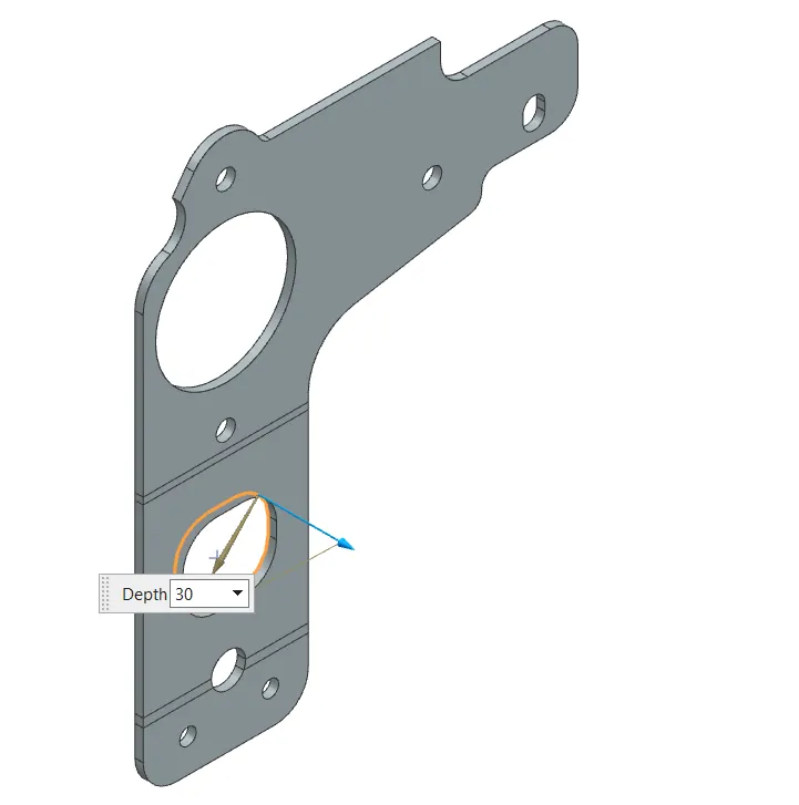
AFTER this i use the advance flange command but i use the student version so the ADVANCE FLANGE command is not their so skip this command .
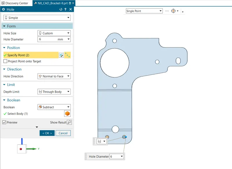
HOLE- This command is used to create holes at desired location.
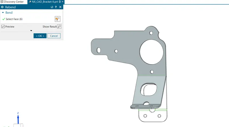
REBEND- This command is used to rebend the unbent areas to obtain the bend features and also to obtain the final sheet metal part.
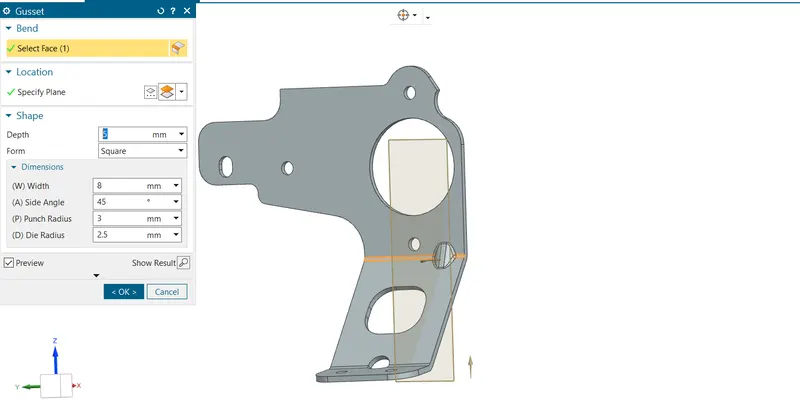
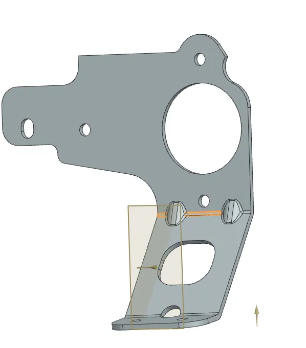
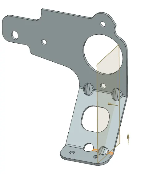
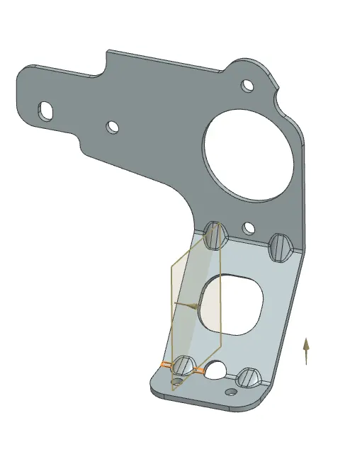
GUSSET:
The commad i used to Gusset
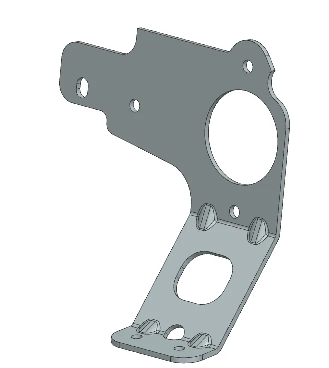
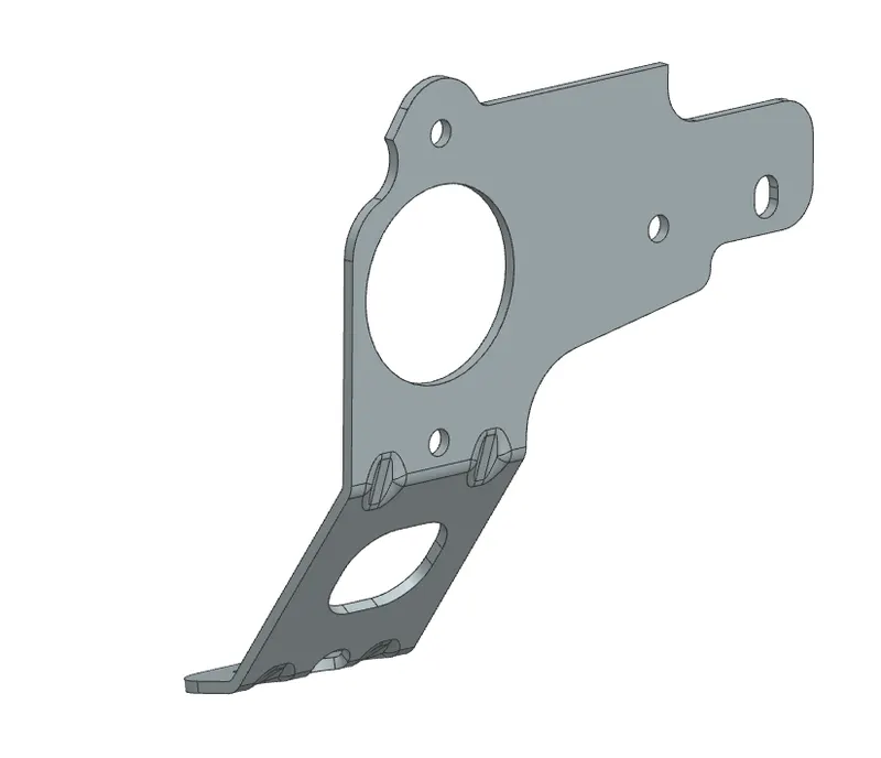
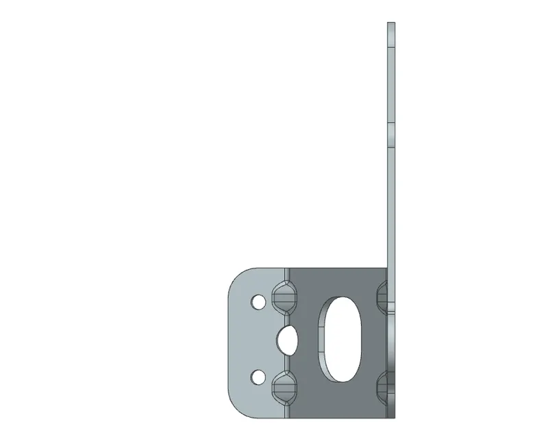
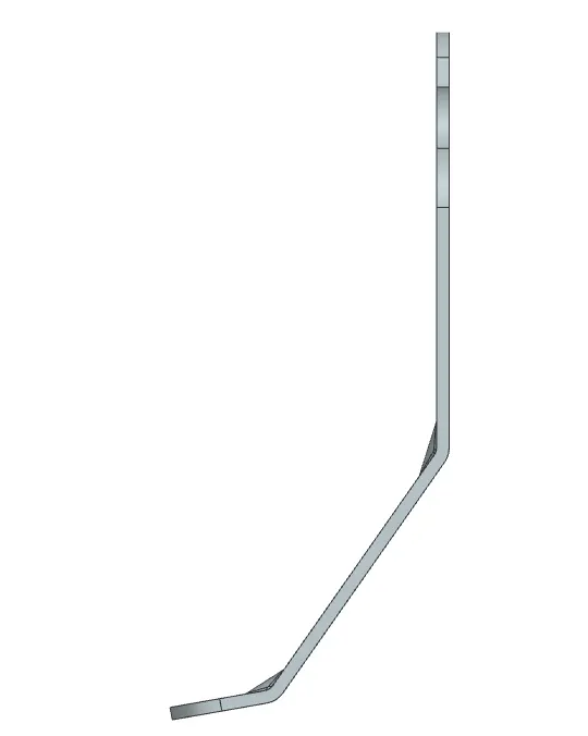
FINAL DESIGN MODEL
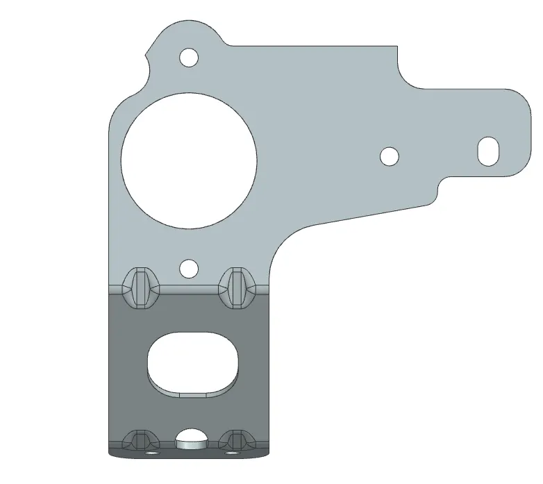
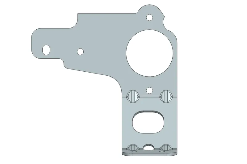
FEATURE TREE
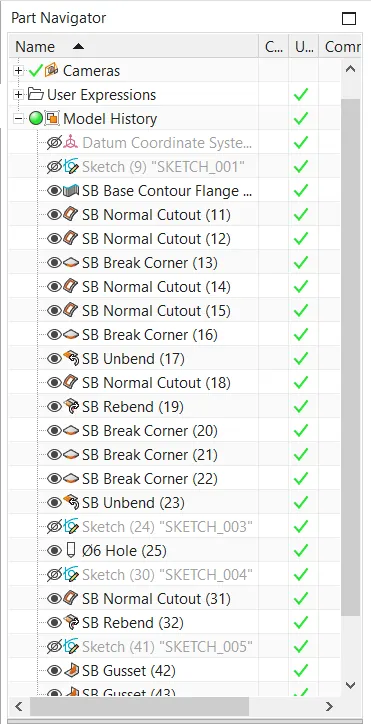
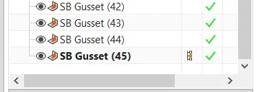
CONCLUSION:
Thus the objective of designing a metal bracket in the NX CAD Sheet metal application is done successfully.