Advanced Sheet Metal Design Using NX Cad Challenge_2_Box Assembly
1.Title-BOX ASSEMBLY
2.OBJECTIVE: To design a sheet metal casing in industrial manner by using Siemens NX Cad.
3.INTRODUCTION: The sheet metal application provides an environment for the design of sheet metal parts used in Machinery, Automotive,Aerospace etc.Enclosures,brackets,and other parts normally manufactured with a brake press.
4.Design methodology / approach:
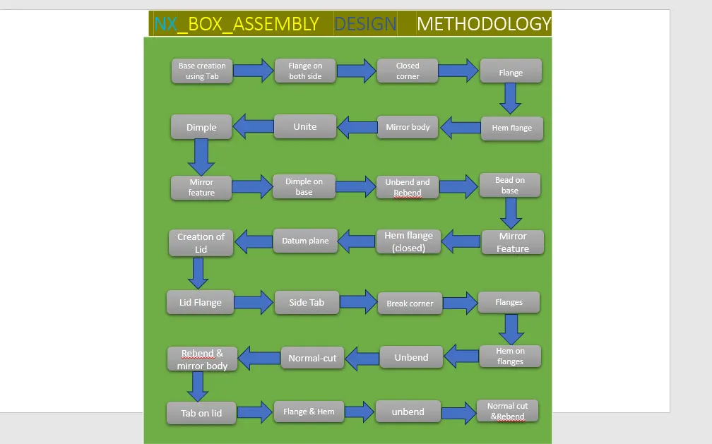
Features used while designing :
- 1.SKETCH: This is used to create a basic sketch of the design according to shape and size on selecting the desired plane.
- 2.TAB: This feature is used to create a base tab on selecting the curve drawn in sketch mode with the appropriate thickness.
- 3.FLANGE: Flange is used to add flanges on selecting the edges of our sheet, it works as a BEND feature along with that extra material can be added by adjusting the length of the flange.
- 4.CLOSED CORNER: This feature is used to close the corners by selecting two flanges.
- 5.HEM FLANGE: This feature is used for different purposes like stiffening and also for easy holding without making any physical hurts.
- 6.DIMPLE: It is used to draw a dimple on selecting a curve for modeling the sheet.
- 7.MIRROR BODY: This feature is used to create a copy of the body part in the opposite direction.
8.MIRROR FEATURE: This feature is used to create a copy of the feature part in the opposite direction.
- 8.BEND: This feature is used to bend the sheet metal along the sketched curve upon our requirement.
- 9.BREAK CORNERS: Break corners is used to make the edges round for easy handling when using.
- 10.NORMAL CUTOUT: This feature is used to cut the portions of the sheet metal by giving sketch curves.
- 11.UNBEND: Unbend is a feature used to analyze the model whether it has perfectly assigned the alignments, which ensures for the modeler to do further operations on it.
- 12.BEADS: This feature is used to create a bead on the sheet which generally strength to flange.
- 13.REBEND: This is used to re-bend the flange which is unbended after all modification.
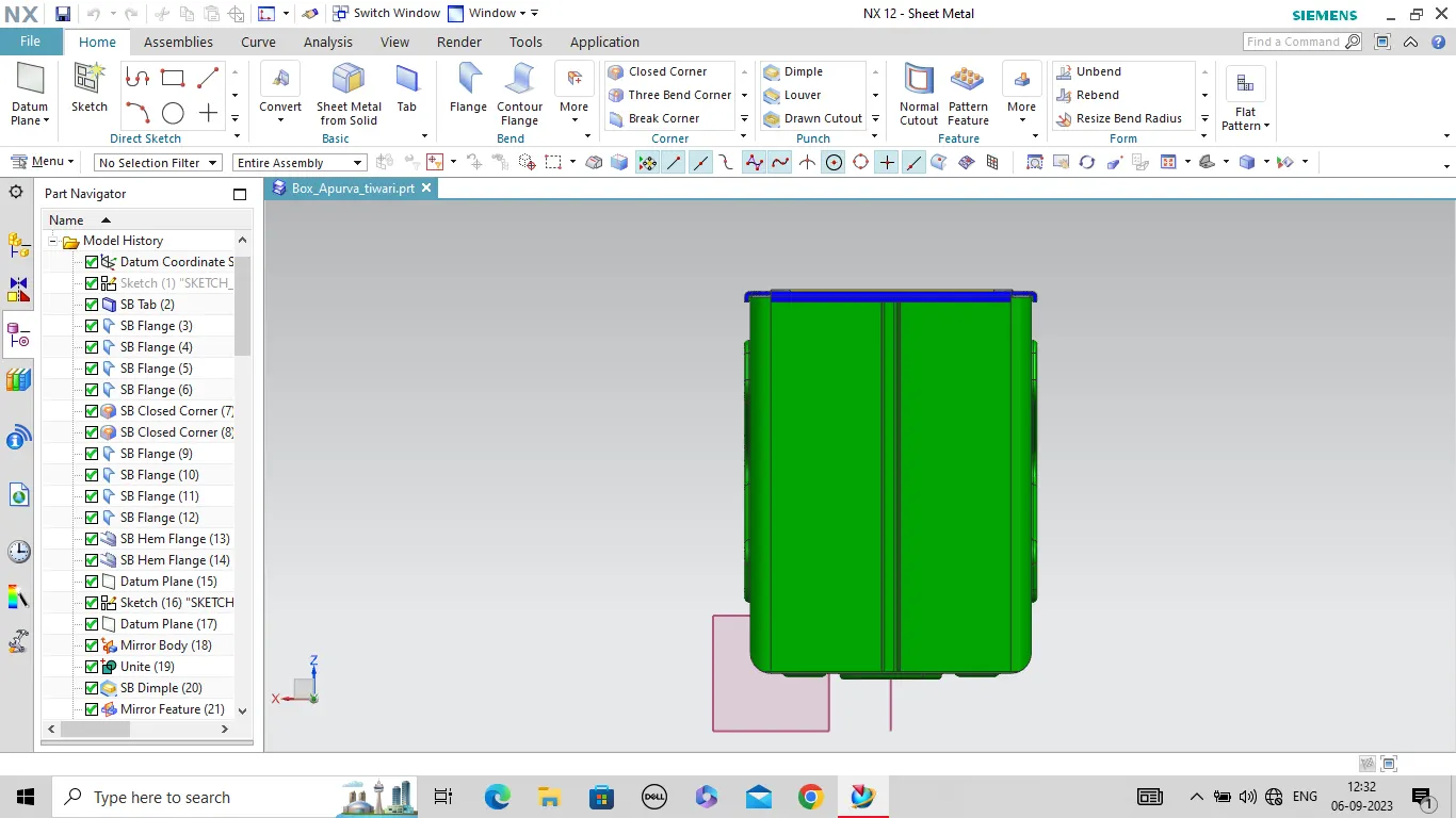
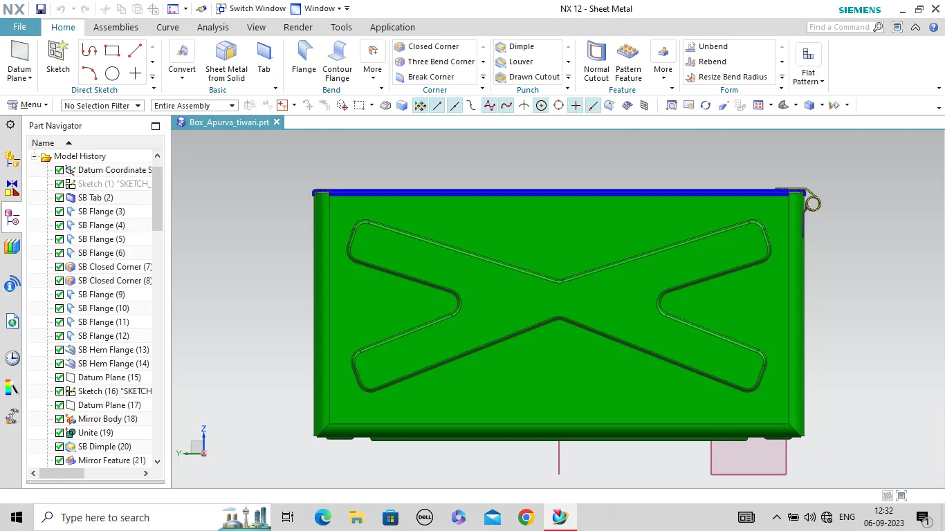
MODEL VIEW: (Front View, Side View, Isometric View and the Top View)
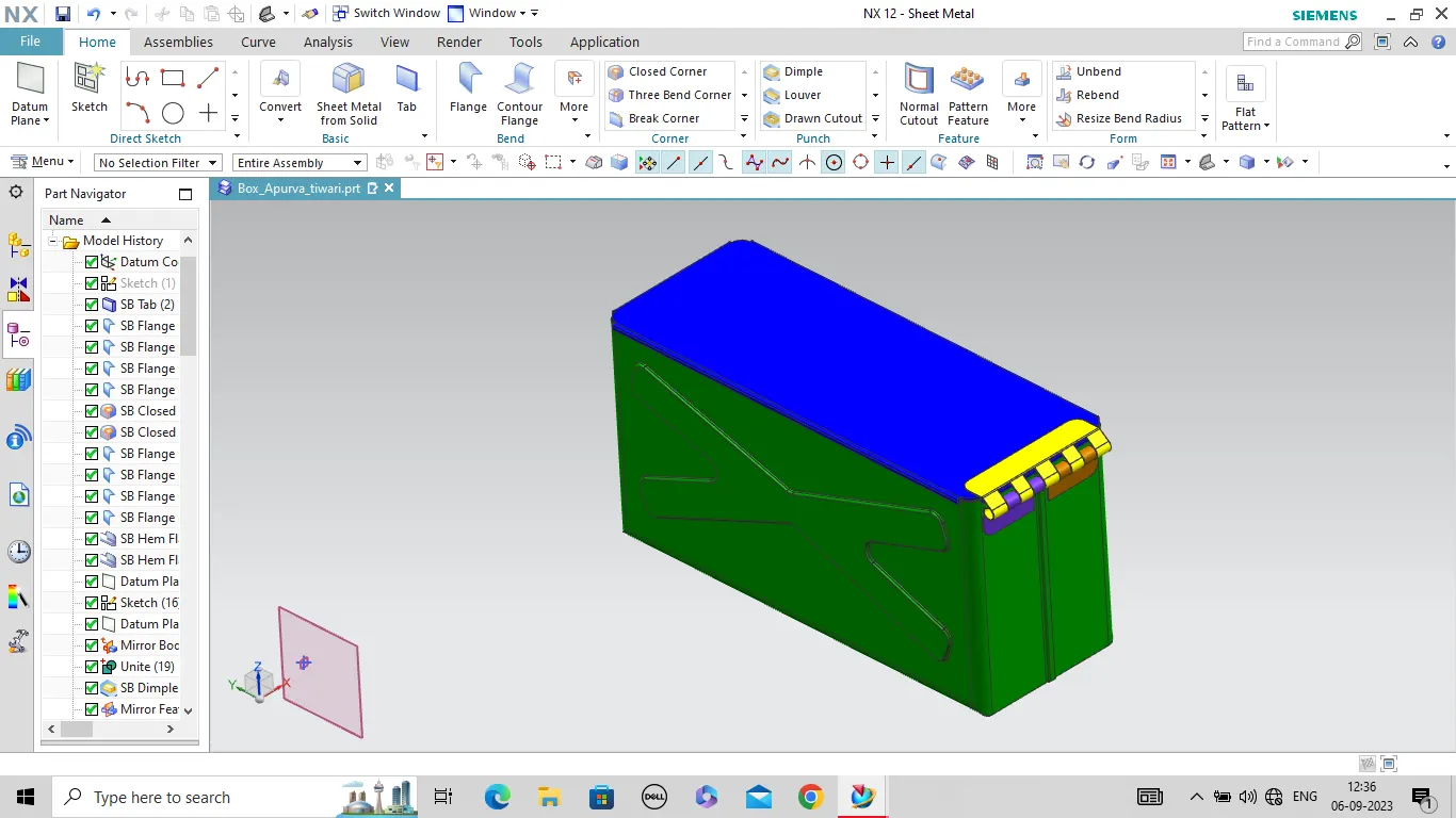
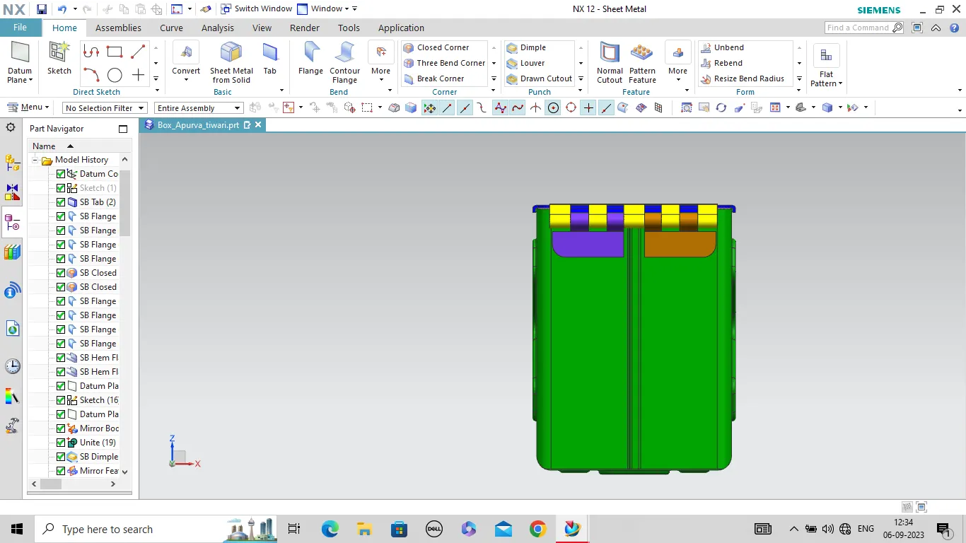
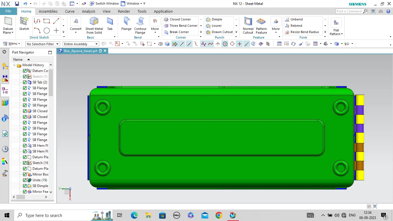
\
Conclusion:After follow above methods and tools we successfully design the sheet metal box assembly.