Week 9 - Challenge 3 - Bumper
Objective:Create the Bumper Plastic component through the given Class-A surface. To begin with, the tooling axis for the given Class-A Surface should be created meeting the requirements of the draft angle and at the end perform the Draft analysis on the model.
Take the Thickness of the component to be 3 mm.
Software Used:Catia v5
Steps involved while creating Switch Bezel component.
- Creation of tooling direction.
- Create class B surface.
- Create class C surface.
- Joined A and C surface.
- Final join all surfaces(A+B+C).
- Create solid component .
Given:
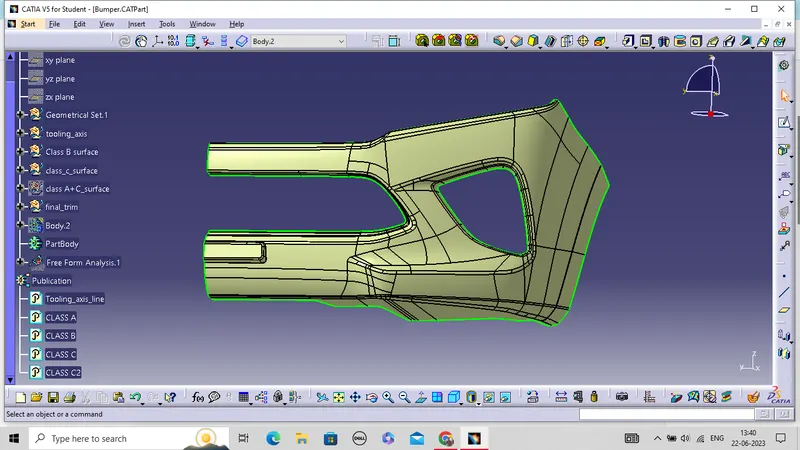
Class-A Surface: Image of given class A surface:
Creation of tooling direction.
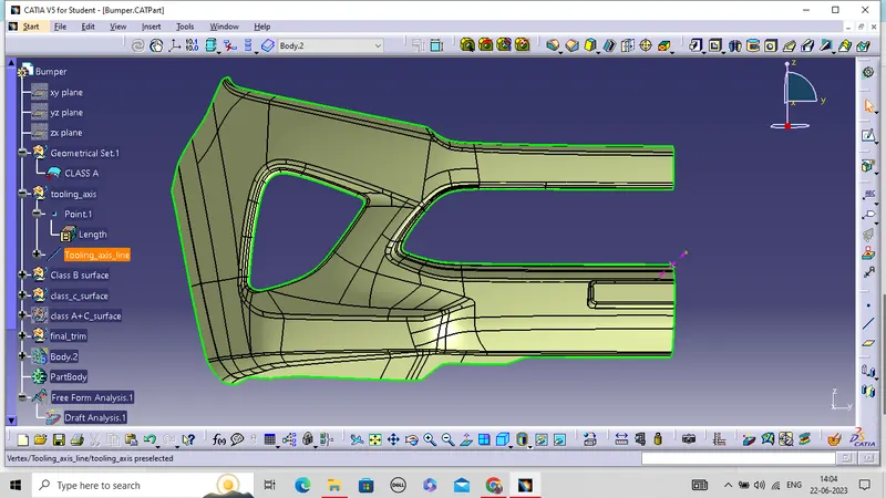
- The direction in which the mould open and close is called tooling direction.
- For tooling axis first we have checked all three axis and found that from x-axis we can see all surfaces and surface patches .
- Then create a point on curve of base surface.
- From that point created a line on X direction and performed draft analysis on Surface A and found that draft analysis is passes for A surface.
- Hence, that line is our tooling axis.
 Create class B surface.
- For creation of B surface we offset class A surface inward by 3 mm which is the thickness of component.
- There are some patches found after offseting.
- we have repaired patches through join ,extrude ,sweep ,multiple extract ,trim command.
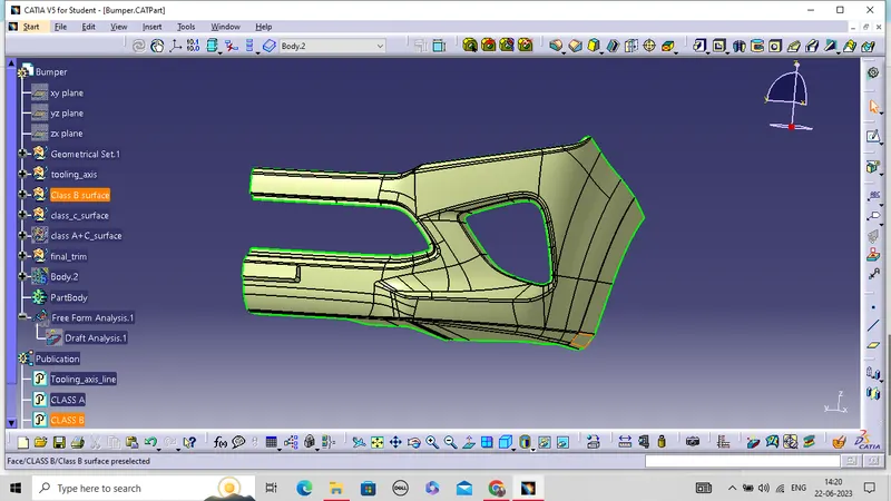
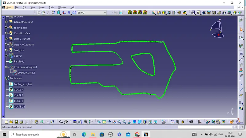
Create class C surface.
- Boundary of class A surface is extracted and middle portion is also extracted .
- Sweep command is used to create C surface at 90 degree of class surface and tooling axis .
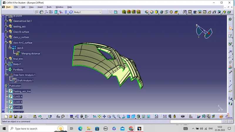
Joined A and C surface. Both the surfaces are join using join commmand.
Final join all surfaces(A+B+C). All surfaces trimmed with class A surface.
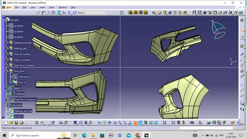
Create solid component .
Finally solid is bodyis created by using close surface command .
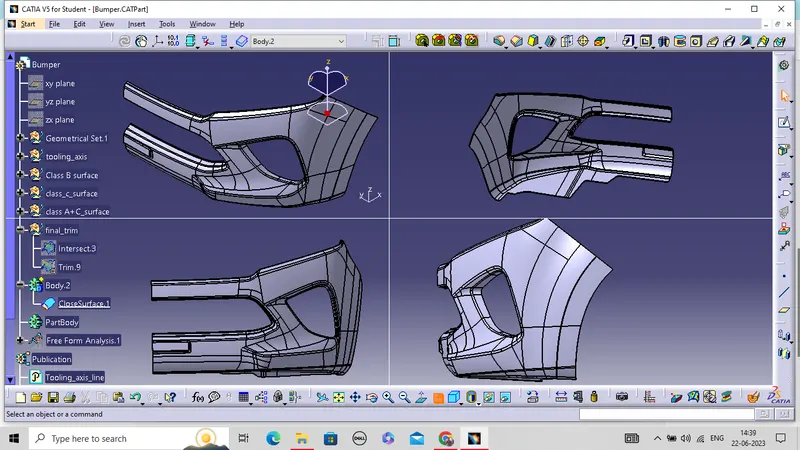
Draft Analysis:
- First the class – A surface is checked before creating the Class –B&C surface and finally the solid body must be analysed. Both can be done by following the below procedures.
- By changing the view mode to custom view parameters – Material mode then the feature draft analysis is enabled.
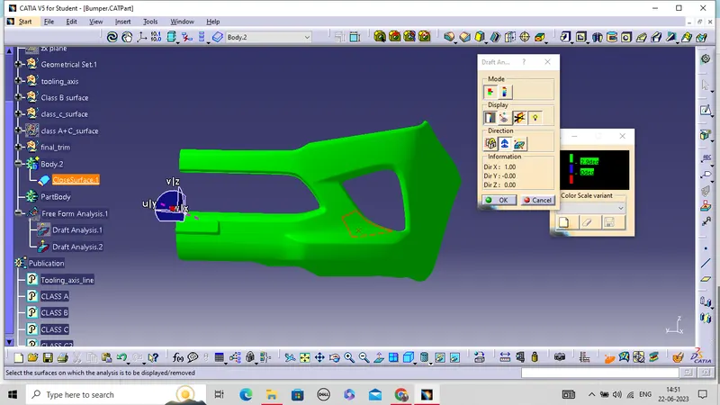
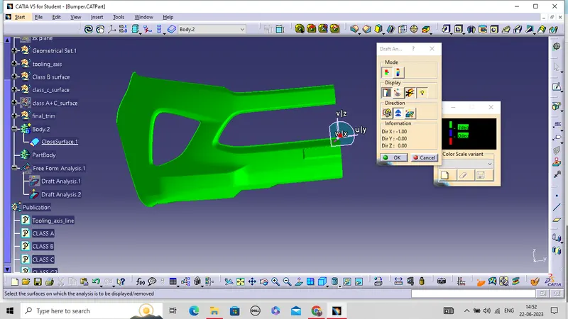
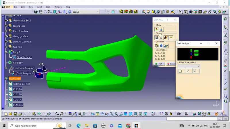
- Then the compass was activated and placed with the tooling axis by dragging the red pointer and then locked it.
- Then, by selecting the quick analysis mode, the nominal value will be 3 degrees and checked for the component's draft angle.
- The green colour area shows that it satisfies the 3-degree draft angle.
for Surface A:
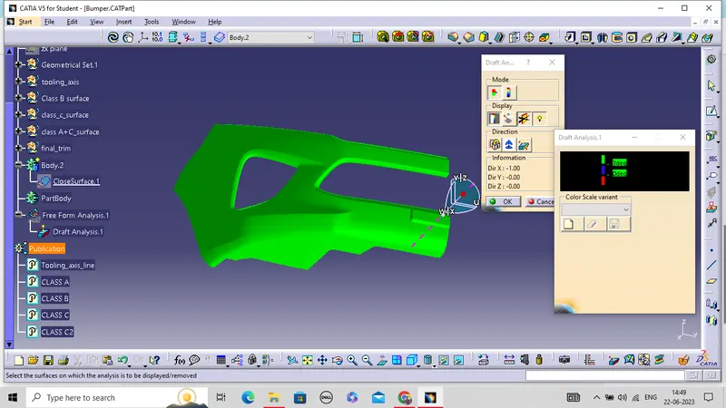
for solid component: