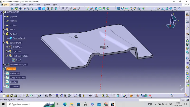
Week 9 - Challenge 1 - Base Bracket Design
REPORT ON BASE BRACKET DESIGN
Aim: To Create the Base Bracket Plastic component through the given Class-A surface. To begin with, the tooling axis for the given Class-A Surface should be created meeting the requirements of the draft angle and at the end perform the Draft analysis on the model .
Software Used: CATIA V5.
Thickness of Plastic Part - 2.5 mm
Steps to create component
- To Create the Tooling Axis.
- To Create the Class B and Class C surface.
- To Create a solid part from Surface.
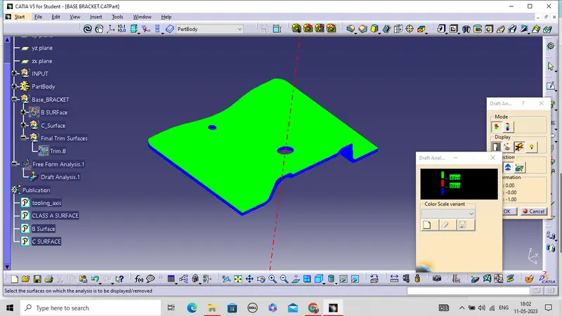
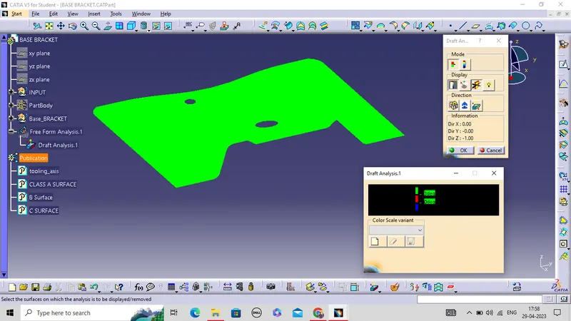
- Draft Analysis of Class A surface and final component.
CLASS A Surface: This Class A Surface is given to us as a input.
Draft Analysis of Surface A: The analysis is done for 3degree draft.
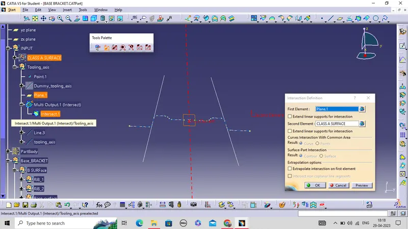
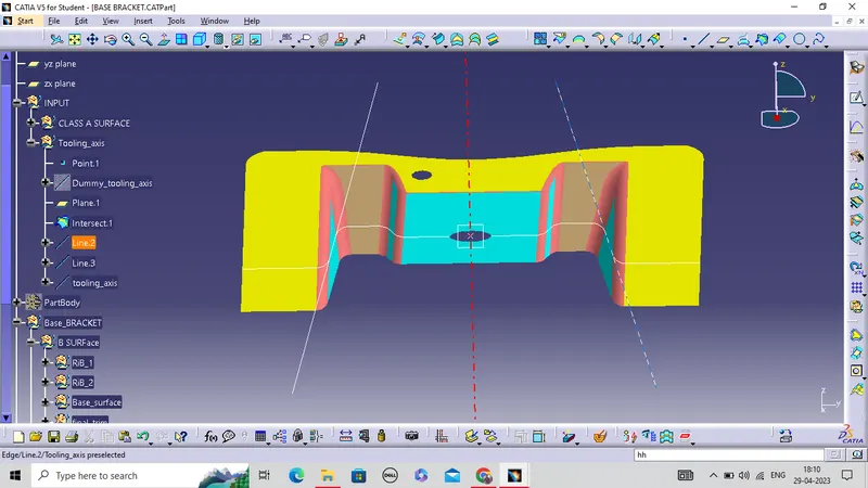
Tooling Axis: First
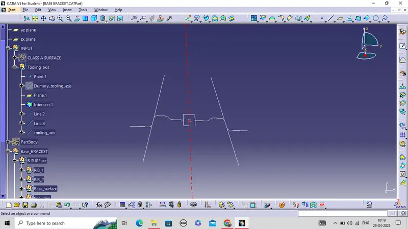
- Create an intersection of CLASS A surface with YZ plane and from the intersection create the tooling axis as shown below.
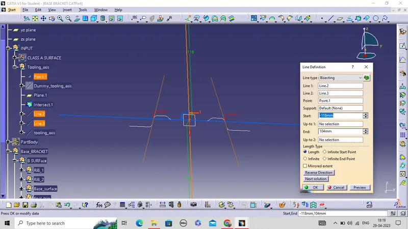
- Then create the two lines on intersection.
- After that create the bisecting line which is the tooling axis for the component.
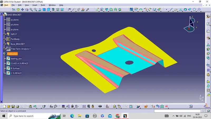
Creation of Class B:
- For the Class B creation, we have extracted surface from Class A and untrimmed them to obtain the original parent surfaces(Rib1,Rib2,Base surface.
- These surfaces are then offset to the required thickness.
- After offsetting, all the surfaces are trimmed into the required shape.
- fillets are provided to the surfaces where required.
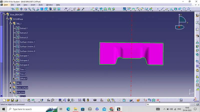
Creation of Class C:
- For creating this surface we have extracted the boundry of Class A using multi-extract and swept the boundary along the draft direction with a 3deg draft.
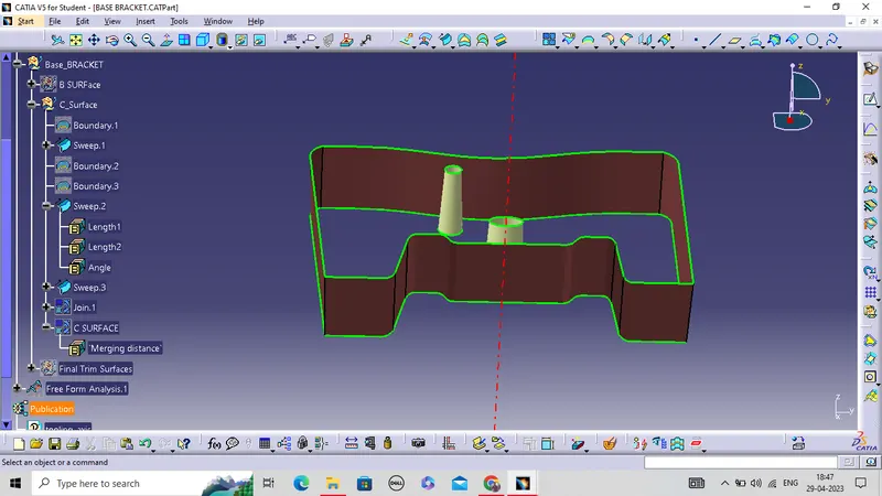
- And join the class C surface with the Class A surface.
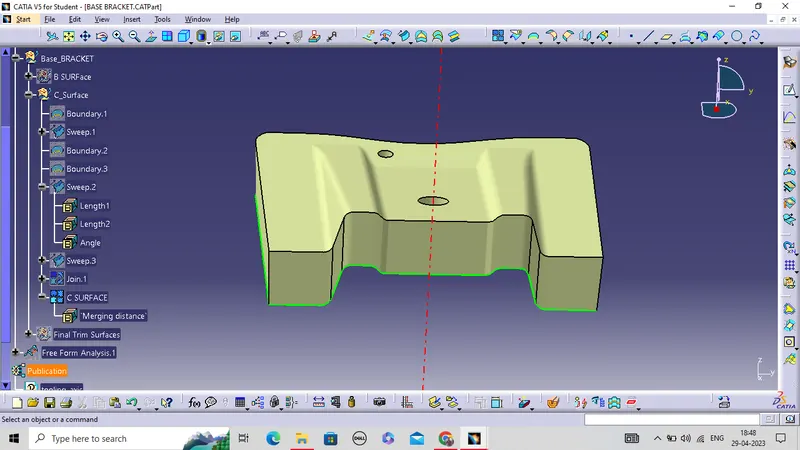
Now after joining the surface B and C and trimming with the surface B.
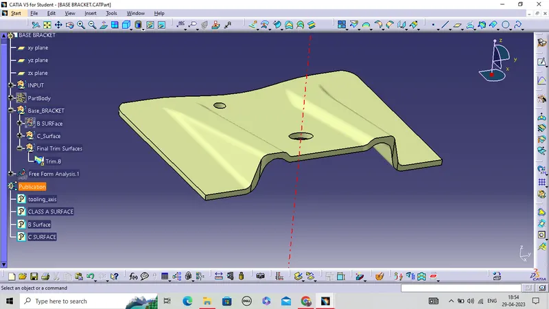
Final Component: Use close