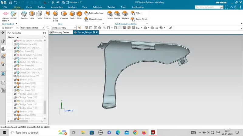
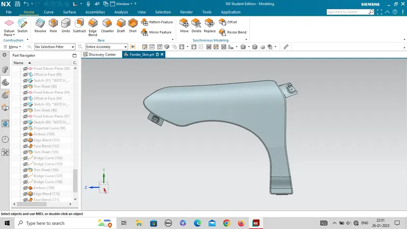
Fender Design
Report on FENDER DESIGN
OBJECTIVE :The objective is to design an automotive front side fender using NX-CAD.
INTRODUCTION:A fender is the part of a car, truck, motorcycle, or other vehicles that frames or covers a wheel well.Its primary purpose is to prevent sand, mud, rocks, liquids, and other road spray from being thrown into the air by the rotating wheel. Fenders are typically rigid and can be damaged by contact with the road surface.
There are Two types of Fenders:
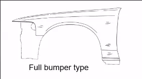
- Full bumper type
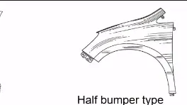
- Half bumper type
1.FULL BUMPER TYPE
Full bumper fender is not used nowadays because they required bigger size blank to produce the part & waste material is also there while manufacturing.
2.HALF BUMPER TYPE
Half bumper fender is used because the waste of material is less & can produce two fender at the same time by slightly increare the raw sheet. and to reduce the weight & cost mostly bumper fender are been produced.
There are 5 typesof mounting area in a automotive fender:
- Drip area
- Sill Mounting
- Bumper mounting
- A-piller mounting
- Splash cover mounting
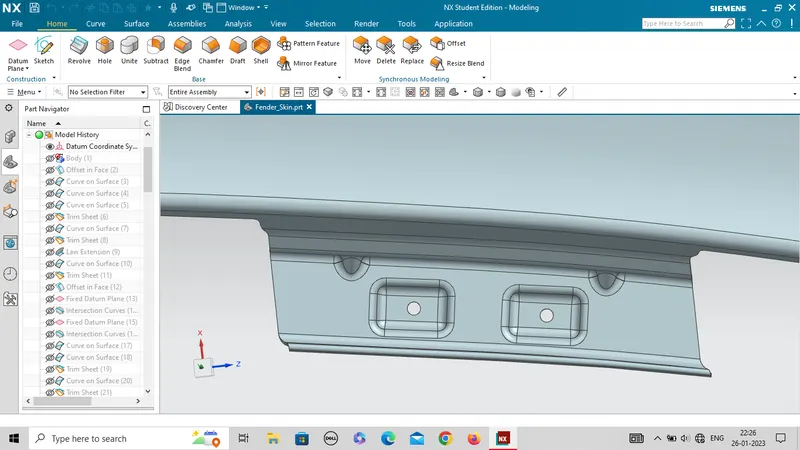
DRIP AREA
- It is the area which the fender is to be attached to engine housing through bolts. There are some standards to design the drip area, from the backside of the fender there should be 200mm clearence for cowl mounting and from the front the side the clearence should be 150mm for the head lamp.
- Cowl top part consists of wiper motor and its instruments
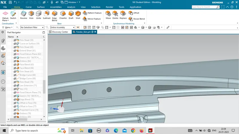
- Considering the above design we have to design embosses, holes to attach the fender to housing & some stiffners to provide strength to the drip area.
- Engine components should not be visible from outside for this we have purposely given 3 degree of angle and 9mm length is given.
- Drip area is very important in designing as it is joined with engine compartment and gives a rigid assemble strength to the whole fender part.
SILL MOUNTING
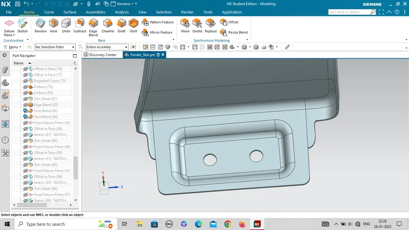
- Sill mounting is a portion fixed to the door sill. Sill is a part of car frame at the bottom.
- The Embossed sill mounting of the fender is attached with the fasteners.
BUMPER MOUNTING
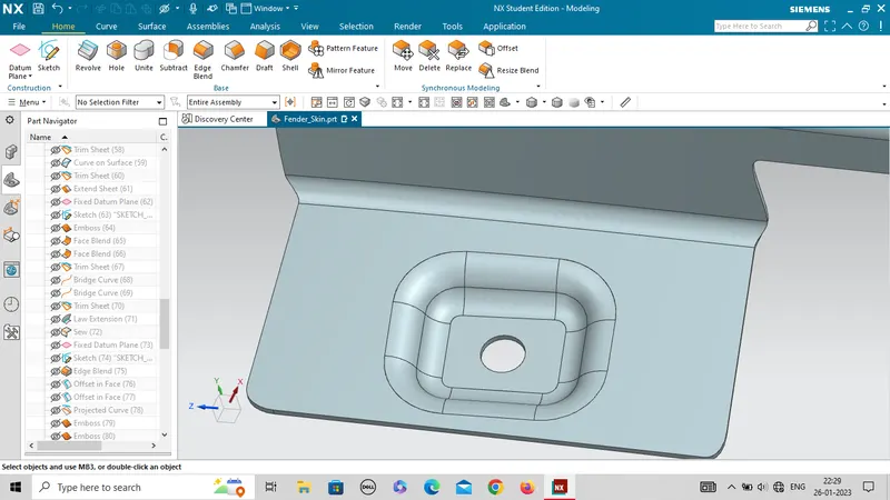
- Bumper is a structure attached to the front and rear end in order the restrict the shock after collision.
- Bumpers are usually made of plastic which covers the front of the car & protect it at time collisions
- This area is mounted to the bumper region.
- The fasteners can also be added in assembling the part.
A-Pillar Mounting
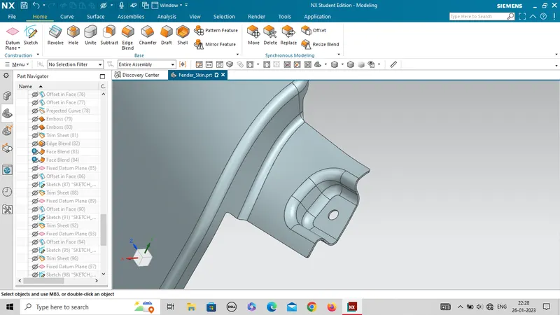
- This Mounting region is located near the cowl of the vehicle where the fender is fastened with the bottom edge of the windshield.
- This mounting is covered with the side rear-view mirror.
BAFFLE MOUNTING
- Baffle mounting or mudguard are clip fit type of mounting on the inner side of the fender arch over the Tyre.
- It is mounted on the fender using a special type of locking clips which are made up of plastics.
- It doesn't need nuts and bolts for mounting so that's why there is no need of embosses.
Manufacturing process
The manufacturing of the fender majorly involves these operations.
1.Embossing
2.Bending
3.Cutting and Blanking
Embossing
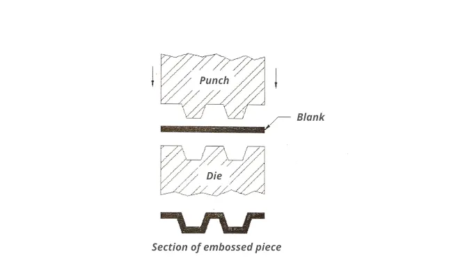
Embossing is a metal forming process for producing raised or sunken designs or relief in sheet material using matched male and female roller dies, theoretically with no change in metal thickness, or by passing sheet or a strip of metal between rolls of the desired pattern.
3 things to control during the embossing of sheet metal
- Pressure: Pressure applied to the sheet metal should be controlled during embossing.
- Heat: Heat level should be maintained consistently during the embossing to get the perfect impressions.
- Die depth: The depth of the die should be adjusted such that the extreme thinning or failure of sheet metal does not occur.
These three factors mostly determine the quality of the embossed product.
During the embossing of sheet metal, the metal sheet is drawn through the male and female roller dies, which ultimately produces a pattern or design on it.
Various types and shapes of dies are used to obtain the desired embossment on the metal sheet.
The combination of pressure and heat is like the principle of ironing the cloth, but here the sheet is depressed instead of straightening.
2.Bending
Metal bending is a process by which metal can be deformed when applying force to the subject, which causes it to bend at an angle and form the anticipated shape, which often results in it being in a ‘V’ or a ‘U’ shape. This is done through the application of force on a workpiece. The force on the work piece can be mechanical, pneumatic or hydraulic.
Cutting and Blanking
Cutting processes are those in which a piece of sheet metal is separated by applying a great enough shearing force to cause the material to fail.
Blanking is a steel manufacturing process in which a flat, geometric shape is created by feeding a coil of sheet metal into a press and die. In this process, the blank is punched out from the large metal sheet.
Design parameters
- The thickness of 0.75 mm inward on the final sewed surface of the fender to the sheet metal parameters
- Drip area design according to given mastersection:
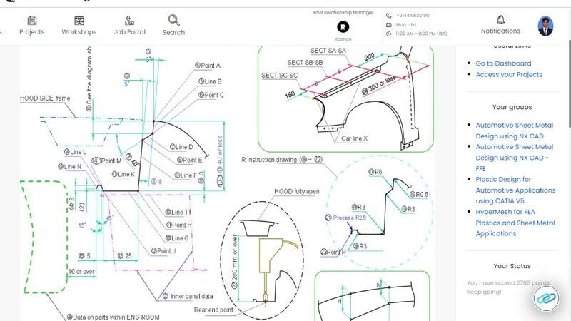
- There should be minimum 5mm flate surface around the holes created in embossed surface .
- The 3.75mm minimum edge blend radius given to edges of embosses.
- Two or three darts should be created in the drip area.
Conclusion:The complete fender is shown as-