Week 12- Final project
OBJECTIVE: To create the a Door Trim panel and its engineering features.
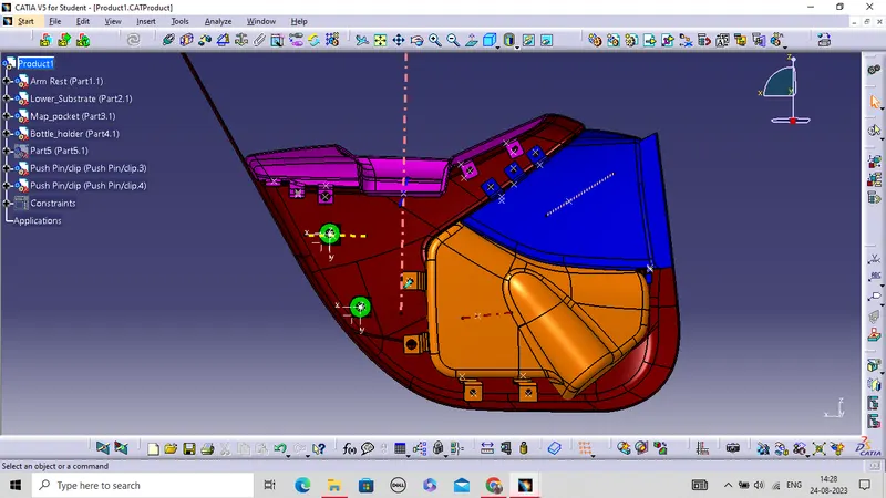
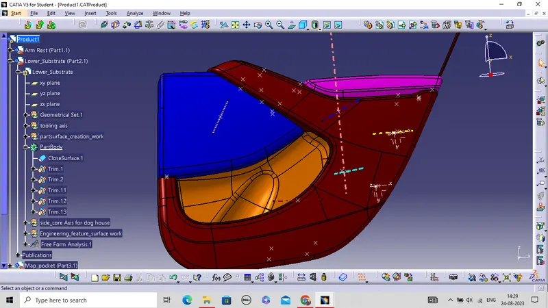
INTRODUCTION: The door trim panel is the interior plastic component attached to the sheet metal part of the Door. It ontains engineering features like a doghouse, heat stakes and pushpins to assemble its components.
Door trim panel is assembly of components such as:-
- Door armrest
- Lower substrate
- map pocket
- bottle holder
Software Used: Catia V5
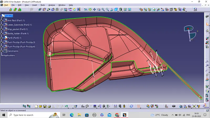
Given: The input provided in this is A surface of components(Door armrest,Lower substrate,map pocket,bottle holder) and mastersection for engineering features:
Steps involved while creating individual components .
- Creation of tooling direction.
- Create class B surface.
- Create class C surface.
- Joined A and C surface.
- Final join all surfaces(A+B+C).
- Create solid component(A-pillar)
- creation of engineering features such as (Flange,heatstakes,locator,Dog House).
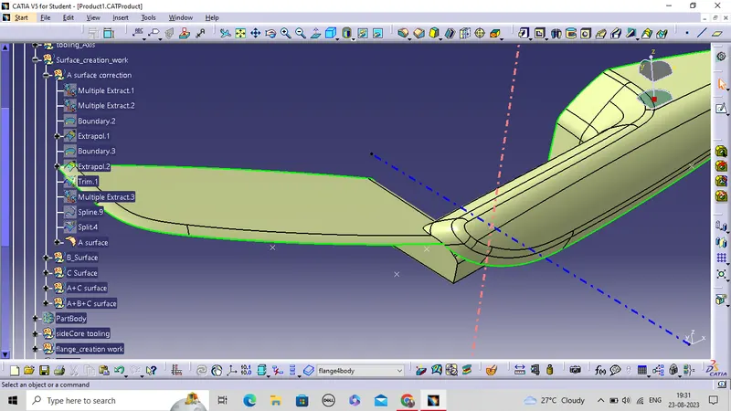
1.DOOR ARMREST: In this the provided class A surface have some discontinuous surface so first we corrected the given surface:
Corrected A surface:
1.Creation of tooling direction.
- The direction in which the mould open and close is called tooling direction.
- For tooling axis first we have checked all three axis.
- Then create a boundary of base surface.
- Now create two line on side of curve.
- Then create a bisecting line using two line and check draft analysis.
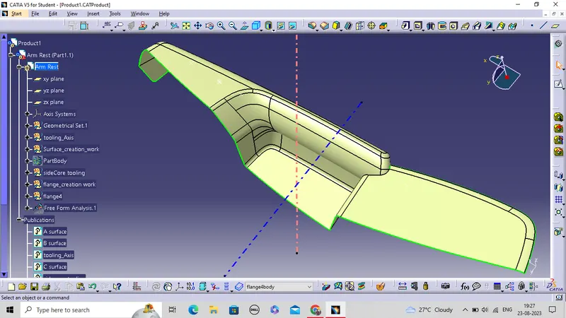
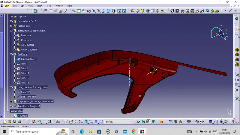
- Hence, that line(dotted-line)is our tooling axis for component and blue dotted line is tooling axis for flang.
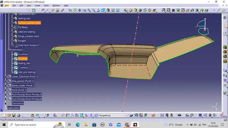
2.Create class B surface.
- For creation of B surface we offset class A surface outward by 2.5 mm which is the thickness of component.
- There are some patches found after offseting.
- we have repaired patches through join ,extrude ,sweep ,multiple extract ,trim,multisection surface command according to need.
3.Create class C surface.
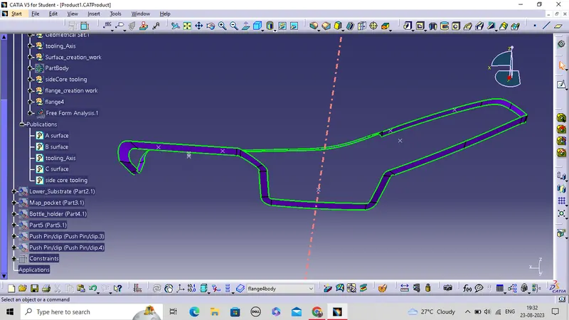
- Create the boundary of class a surface and by using sweep command create surface.
- Then join all the surfaces.
- Ensure that there is no any gap between the surfaces.
4.Joined A and C surface.
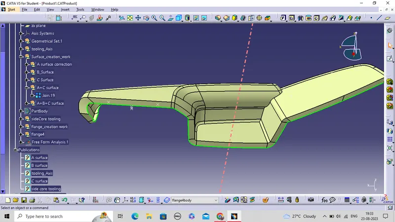
- Now join A and C surface together.
5.Final join all surfaces(A+B+C).
- Now trim the A+C surface with B surface.
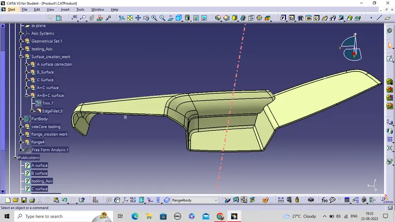
6.Create solid component
- Now create a solid component using close surface command.
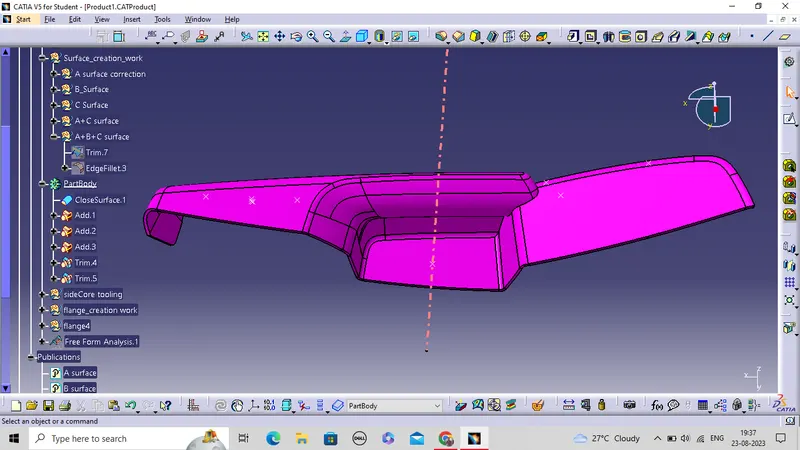
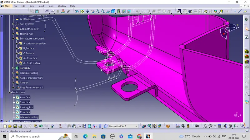
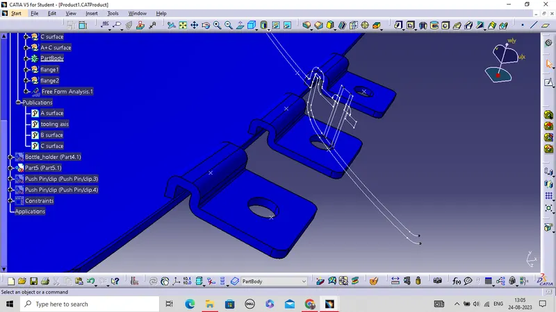
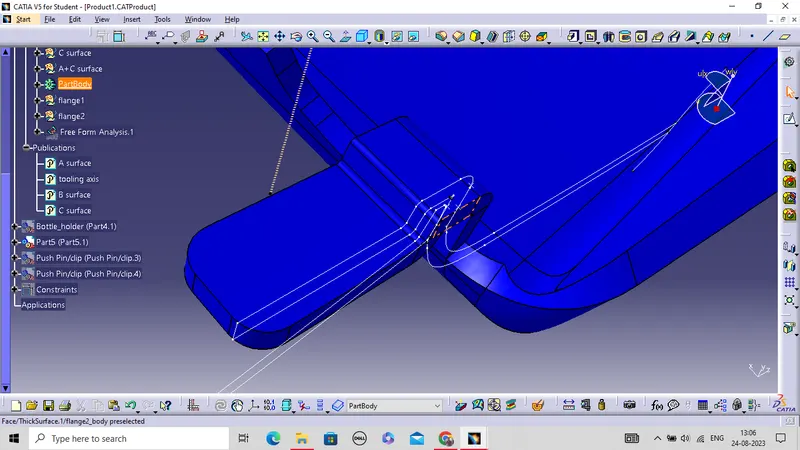
7.Creation of flanges: Flanges are created by given mastersection.for flanges first create sketch according mastersection then using surface command like sweep ,extrude .Thicken command is used to convert surface to solid.
LOWER SUBSTRATE:
1.Creation of tooling direction.
- For tooling axis first we have checked all three axis.
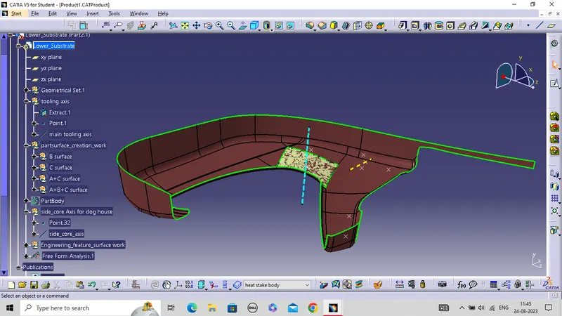
- Then extract the lower surface of given A surface and create a midpoint on that surface.
- Create a line using point and direction and create a line y-direction and check draft analysis.
- Hence,draft analysis is clearing so this line will work as main tooling axis.
2.Create class B surface.
- For creation of B surface we offset class A surface outward by 2.5 mm which is the thickness of component.
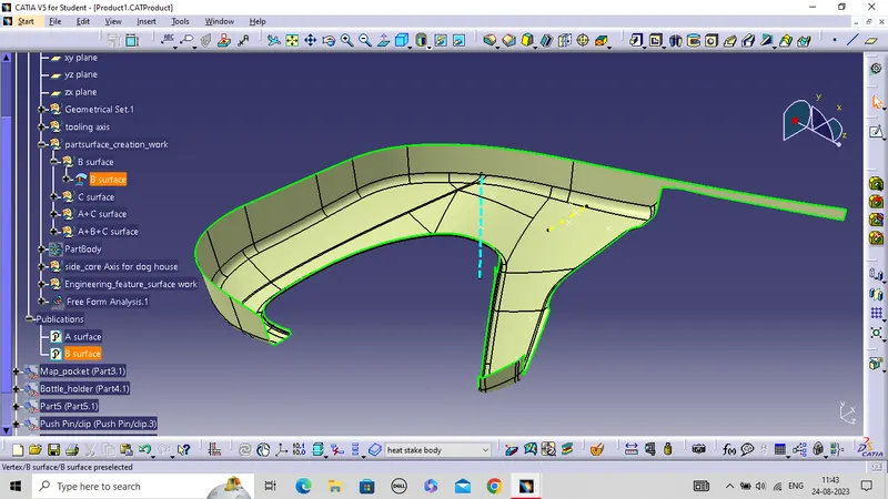
3.Create class C surface.
- Create the boundary of class a surface and by using sweep command create surface.
- Then join all the surfaces.
- Ensure that there is no any gap between the surfaces.
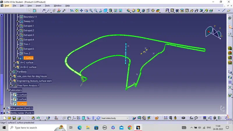
4.Joined A and C surface.
- Now join A and C surface together.
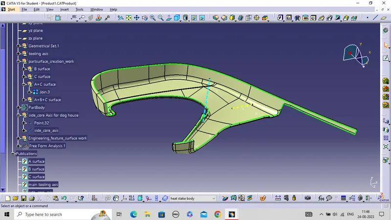
5.Final join all surfaces(A+B+C).
- Now trim the A+C surface with B surface.
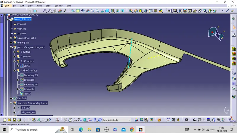
6.Create solid component
- Now create a solid component using close surface command.
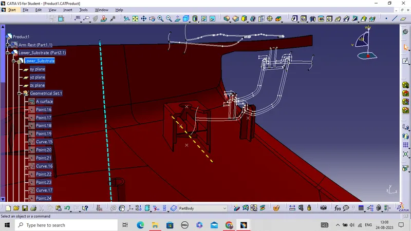
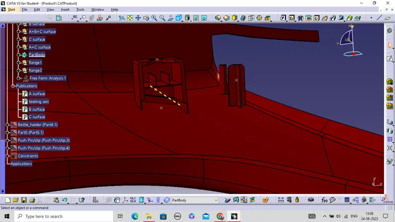
Creation of engineering features -Heat stakes,Locator,Dog house:
MAP POCKET:
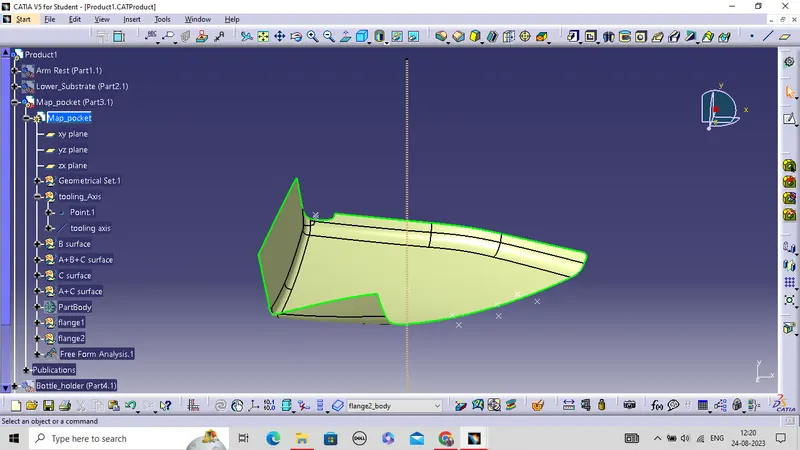
1.Creation of tooling direction.
- For tooling axis first we have checked all three axis.
- Then extract the lower surface of given A surface and create a midpoint on that surface.
- Create a line using point and direction and create a line y-direction and check draft analysis.
- Hence,draft analysis is clearing so this line will work as main tooling axis.
2.Create class B surface.
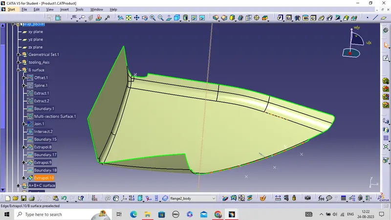
- For creation of B surface we offset class A surface by 2.5 mm which is the thickness of component.
- There are some patches found after offseting.
- we have repaired patches through join ,extrude ,sweep ,multiple extract ,trim,multisection surface command according to need.
3.Create class C surface.
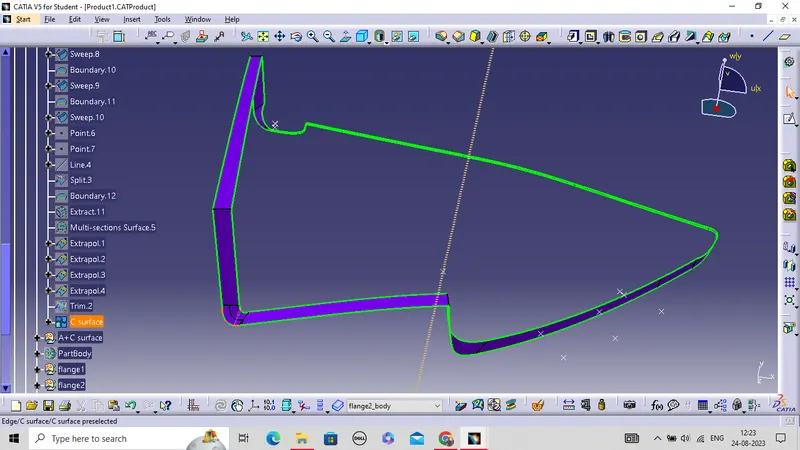
- Create the boundary of class a surface and by using sweep command create surface.
- Then join all the surfaces.
- Ensure that there is no any gap between the surfaces.
4.Joined A and C surface.
- Now join A and C surface together.
5.Final join all surfaces(A+B+C).
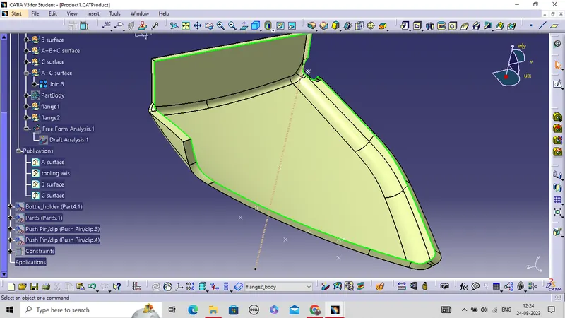
- Now trim the A+C surface with B surface.
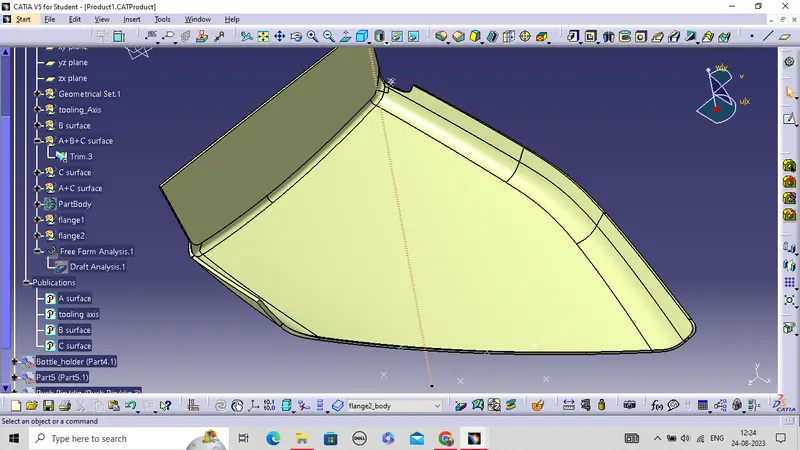
6.Create solid component
- Now create a solid component using close surface command.
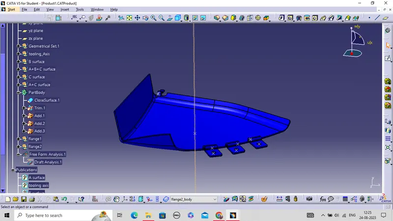
Creation of flanges:
BOTTLE HOLDER:
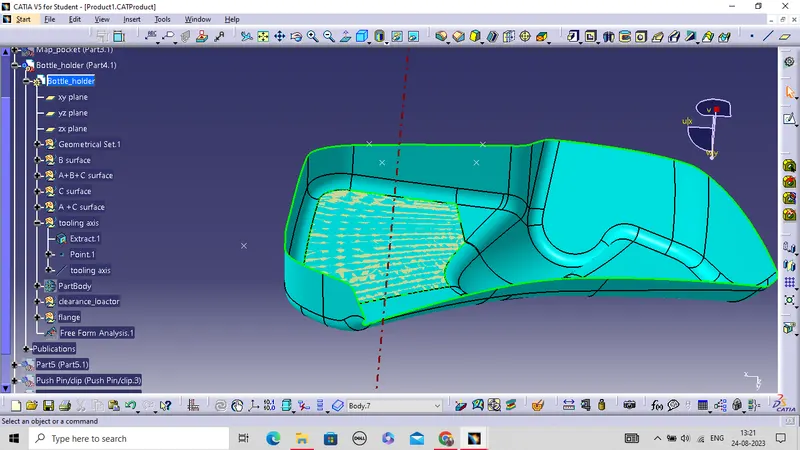
1.Creation of tooling direction.
- For tooling axis first we have checked all three axis.
- Then extract lower surface.
- Now create point on surface.
- Then create line using point and direction check draft analysis.
- Hence, that line(dotted-line)is our tooling axis .
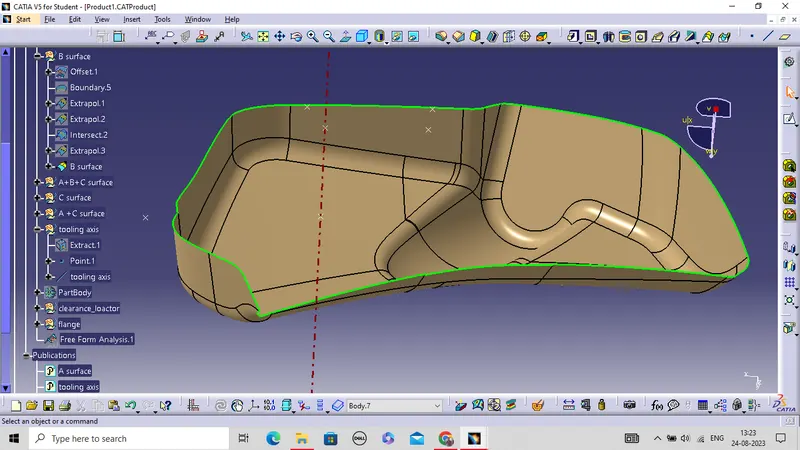
2.Create class B surface.
- For creation of B surface we offset class A surface outward by 2.5 mm which is the thickness of component.
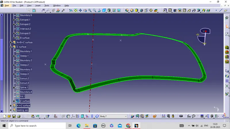
3.Create class C surface.
- Create the boundary of class a surface and by using sweep command create surface.
- Then join all the surfaces.
- Ensure that there is no any gap between the surfaces.
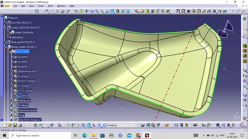
4.Joined A and C surface.
- Now join A and C surface together.
5.Final join all surfaces(A+B+C).
- Now trim the A+C surface with B surface.
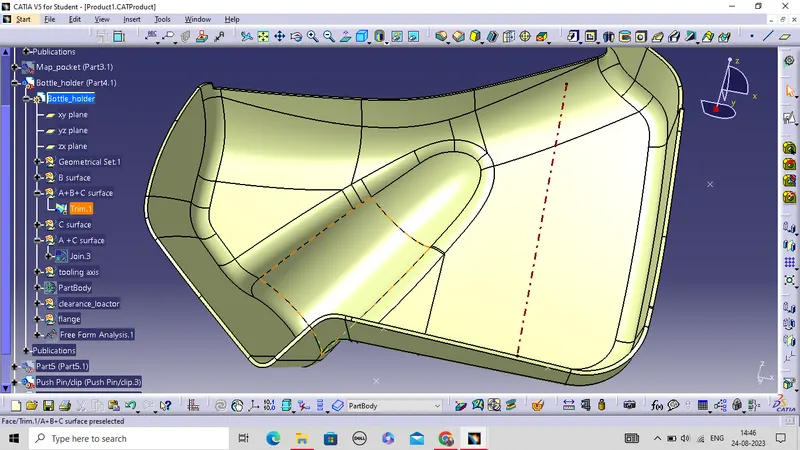
6.Create solid component
- Now create a solid component using close surface command.
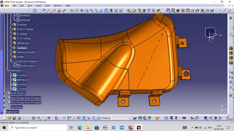
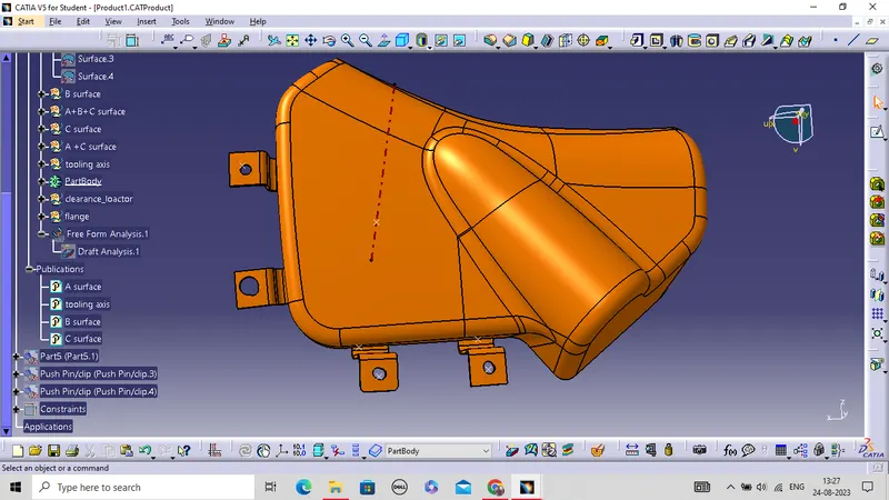
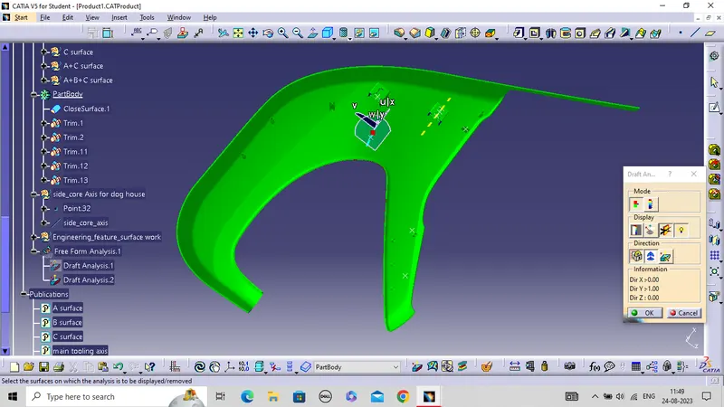
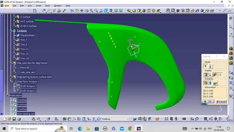
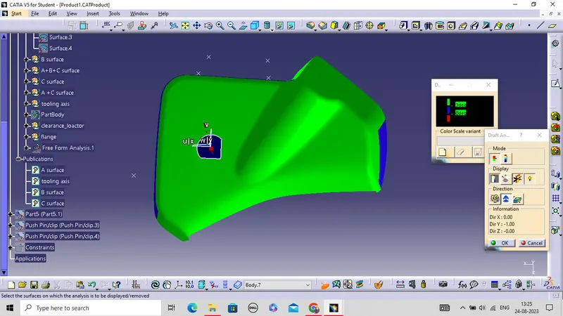
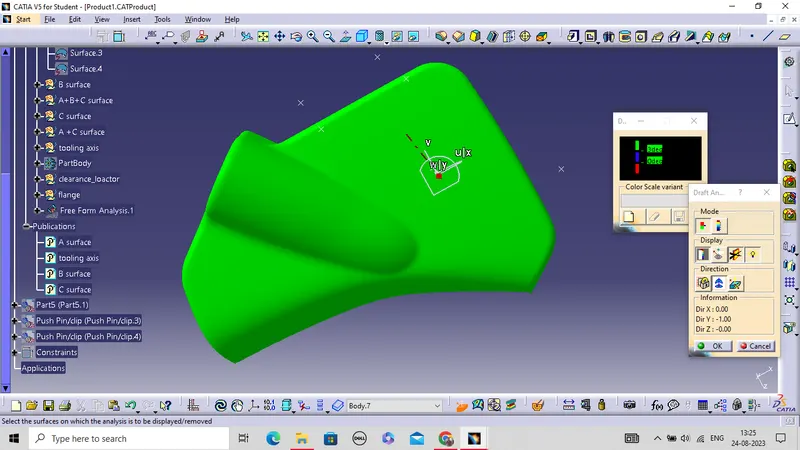
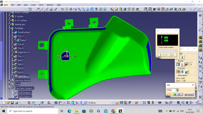
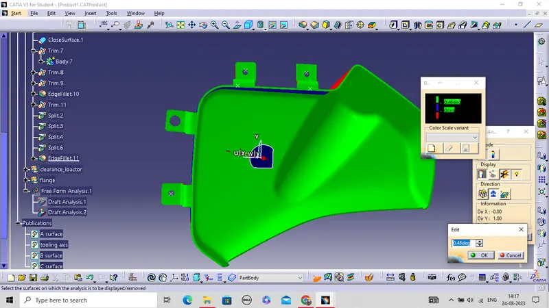
Draft Analysis:
- First the class – A surface of all component is checked before creating the Class –B&C surface and finally the solid body must be analysed. Both can be done by following the below procedures.
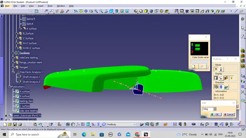
- By changing the view mode to custom view parameters – Material mode then the feature draft analysis is enabled.
- Then the compass was activated and placed with the tooling axis by dragging the red pointer and then locked it.
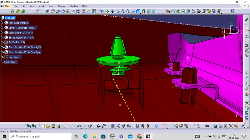
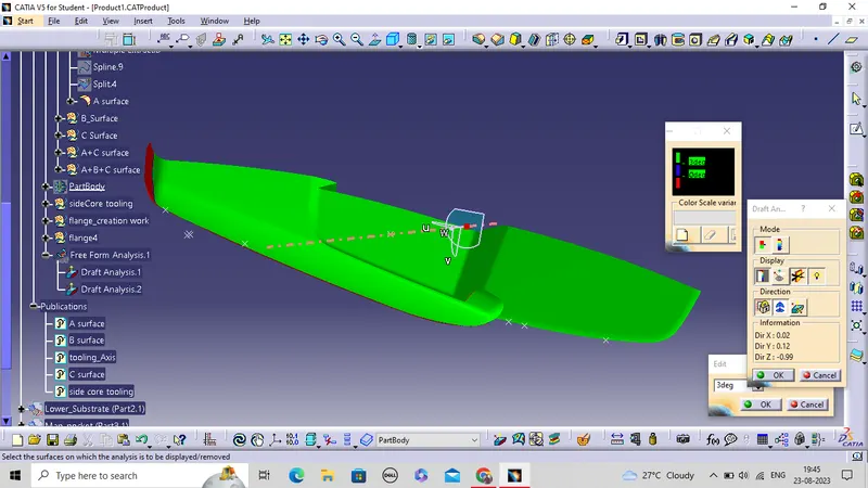
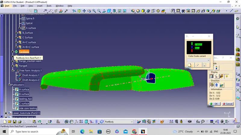
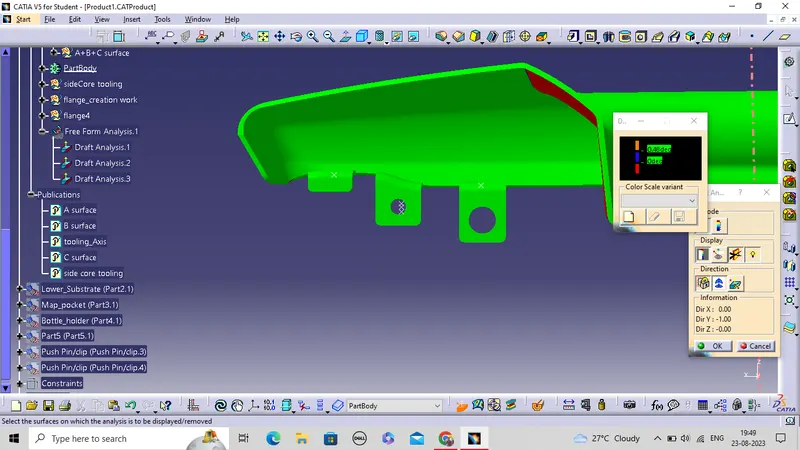
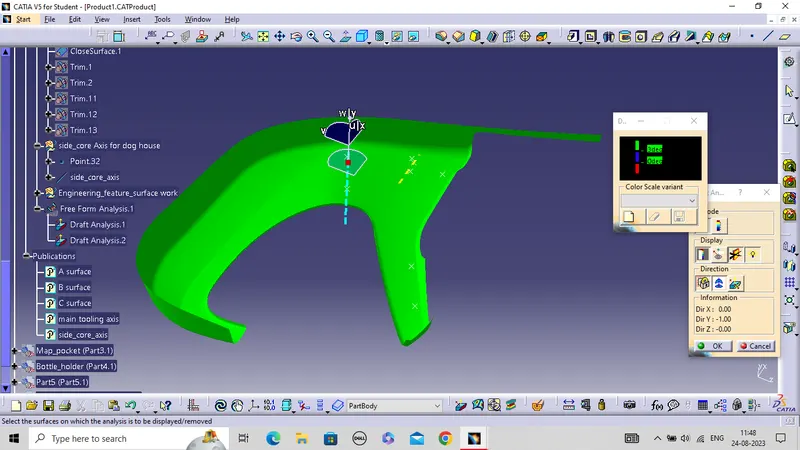
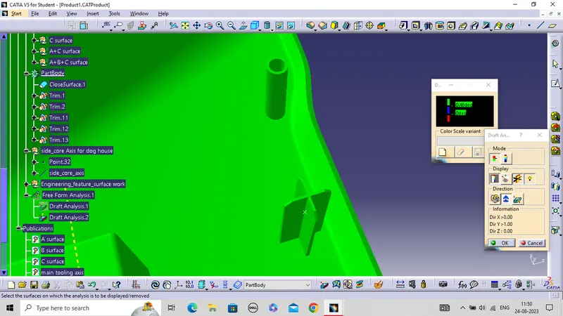
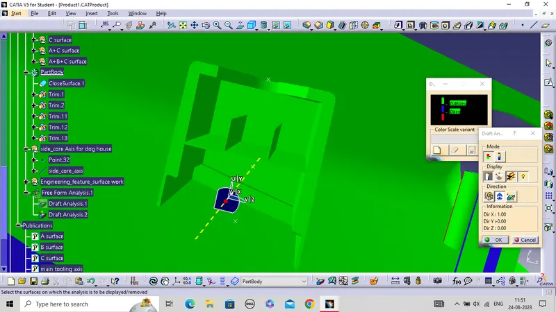
- Then, by selecting the quick analysis mode, the nominal value will be 3 degrees and checked for the component's draft angle and at angle 1.5 degree the Dog house outer face and at 0.5 degree inside faces of dog house and all flanges will check.
- The green colour area shows that it satisfies at given draft angle.
A SURFACE OF ARM REST:
SOLID BODY OF ARM REST:
FLANGES OF ARM REST:
A SURFACE OF LOWER SUBSTRATE:
SOLID BODY SUBSTRATE:
HEAT STAKES AND FOUR WAY LOCATOR:
DOG HOUSE INNER SURFACE:
A SURFACE MAP POCKET:
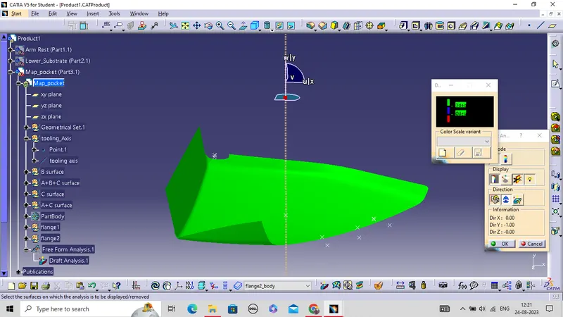
FLANGES OF MAP POCKET
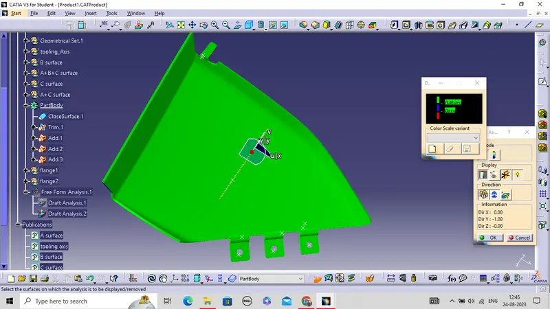
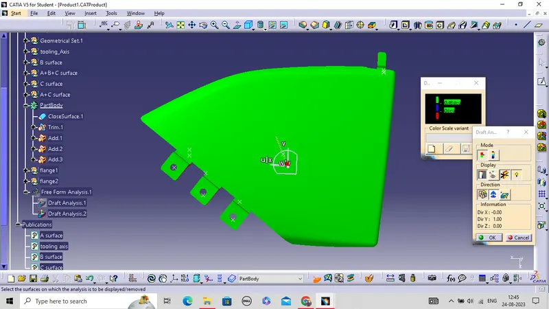
SOLID BODY OF MAP POCKETl:
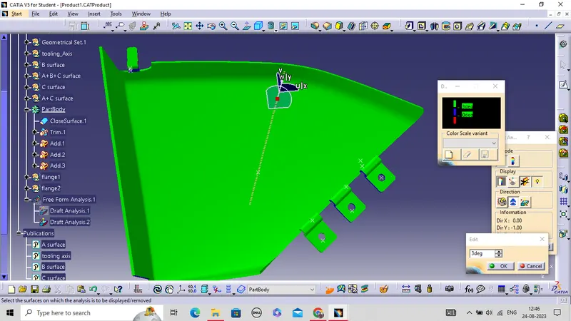
A SURFACE OF BOTTLE HOLDER:
ASSEMBLY OF ALL COMPONENTS OF DOOR TRIM: