Advanced Sheet Metal Design Using NX Cad Challenge_6_Bracket
1.Title of the Project: Nx_Bracket using Nx cad
2. Objective: To design a sheet metal Bracket in industrial manner by using Siemens NX Cad.
3.Introduction: The sheet metal application provides an environment for the design of sheet metal parts used in Machinery, Automotive,Aerospace etc.Enclosures,brackets,and other parts normally manufactured with a brake press.
4.Design methodology / approach (Flowchart):
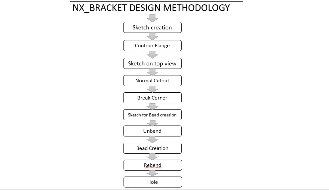
Description of used tool:
SKETCH: This is used to create a basic sketch of the design according to shape and size on selecting the desired plane.
Contour Flange: In Nx sheet metal contour flange command use to create a base feature by extruding a sketch along a vector, or adds material by sweeping a sketch along an edge or chain of edge
BREAK CORNERS: Break corners is used to make the edges round for easy handling when using.
NORMAL CUTOUT: This feature is used to cut the portions of the sheet metal by giving sketch curves.
UNBEND: Unbend is a feature used to analyze the model whether it has perfectly assigned the alignments, which ensures for the modeler to do further operations on it.
BEADS: This feature is used to create a bead on the sheet which generally strength to flange.
REBEND: This is used to re-bend the flange which is unbended after all modification.
Hole: Hole feature is used to generate hole with definite parameter on sheet metal in Siemens NX. We can create different types of holes using this feature
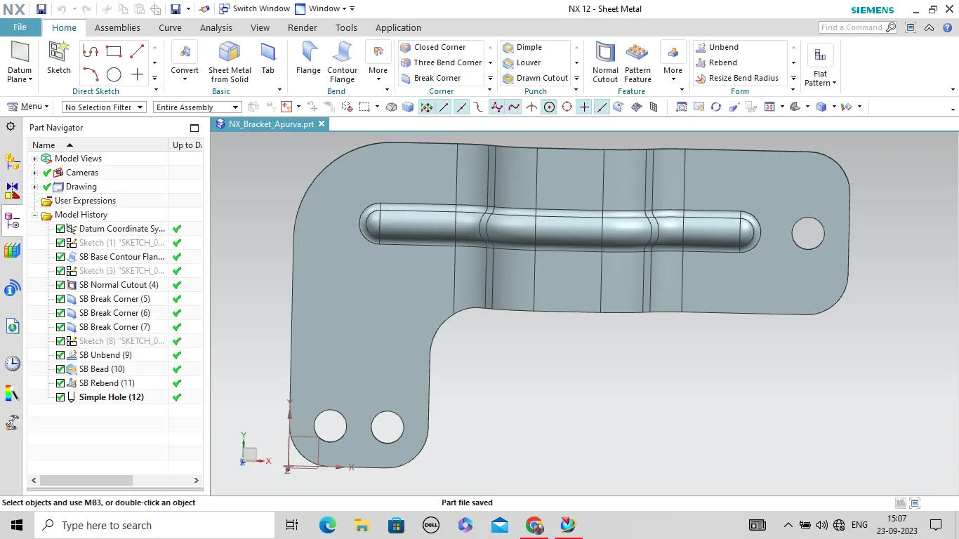
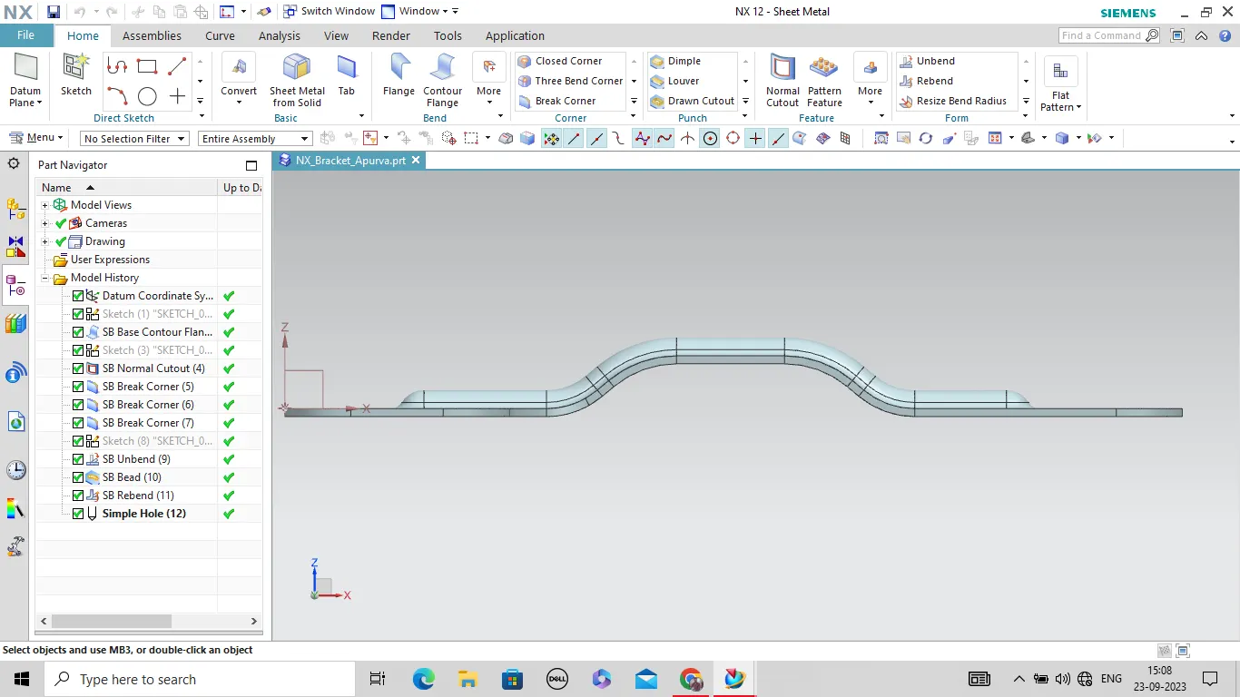
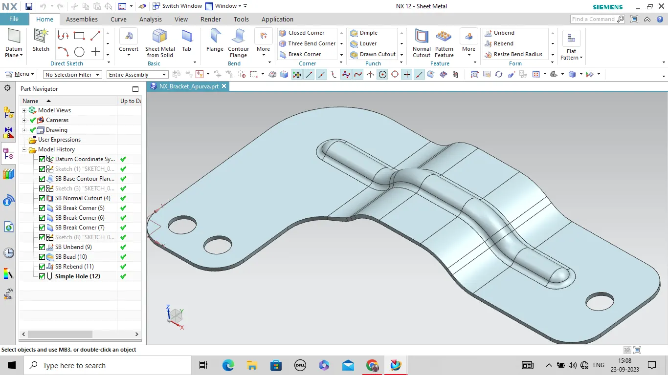
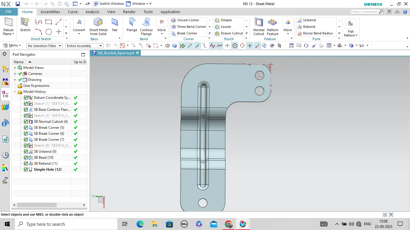
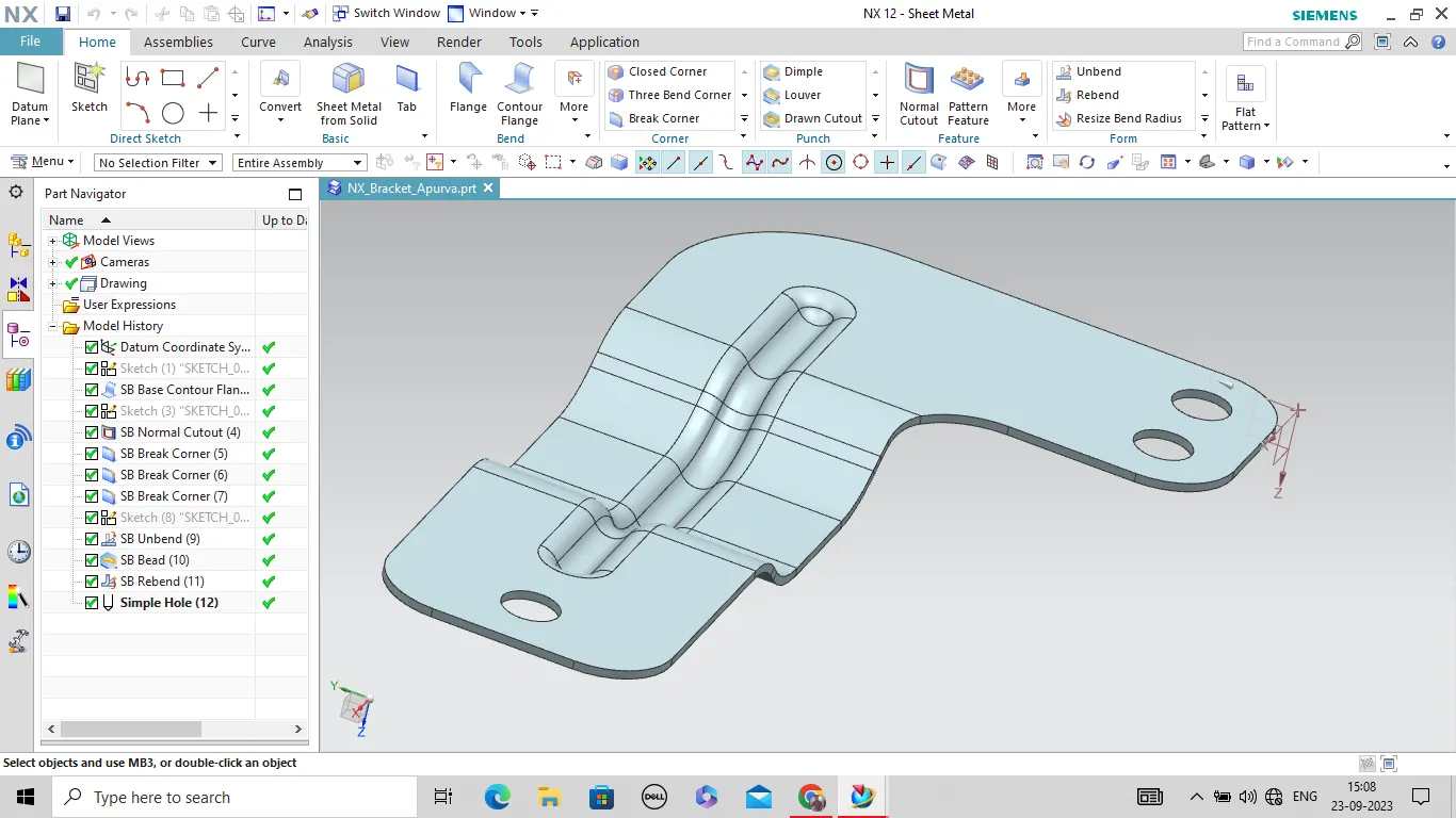
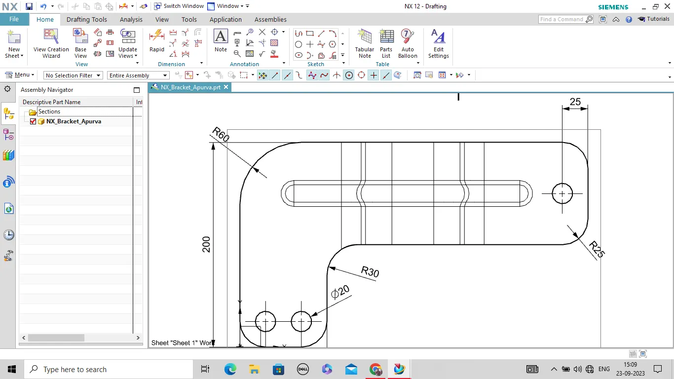
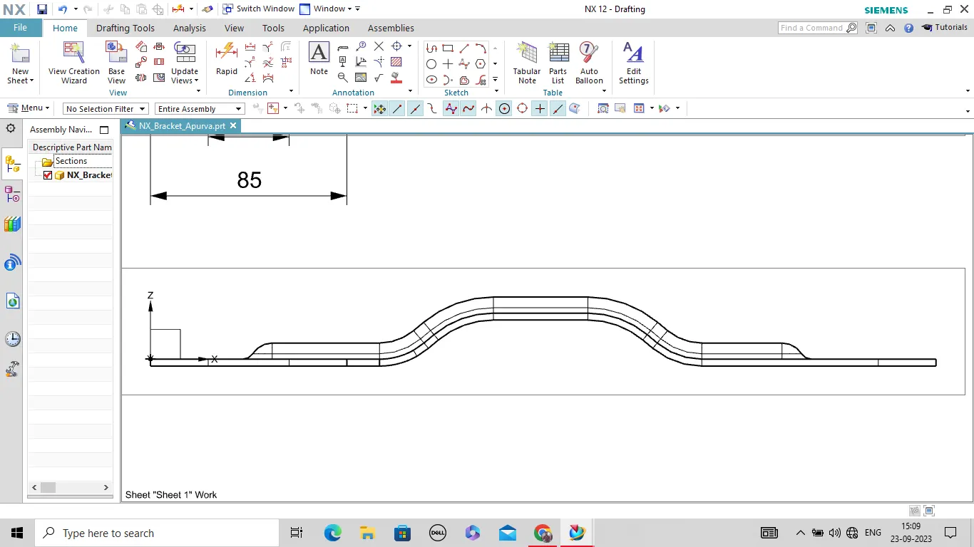
Model Images of different different view:
Conclusion: After follow above methods and tools we successfully design the sheet metal bracket.