Week 10 - Challenge 1- Attachment Feature Creation (Ribs & Screw Boss)
OBJECTIVE: To create the rib and screw boss for the door handle considering the design rules for the rib creation and screw boss creation and then perform the draft analysis for class A rib,screw boss and final component.
Given: Class A srface.
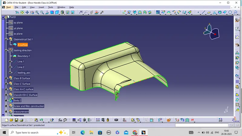
Software Used:Catia v5
Steps involved while creating Switch Bezel component.
- Creation of tooling direction.
- Create class B surface.
- Create class C surface.
- Joined A and C surface.
- Final join all surfaces(A+B+C).
- Create solid component
- creation of Ribs
- Creation of screw boss
1.Creation of tooling direction.
- The direction in which the mould open and close is called tooling direction.
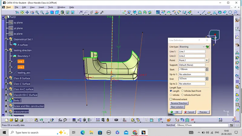
- For tooling axis first we have checked all three axis.
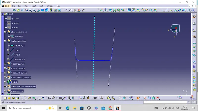
- Then create a boundary of base surface.
- Now create two line on side of curve..
- Then create a bisecting line using Line1 and Line2 and check draft analysis.
- Hence, that line is our tooling axis
2.Create class B surface.
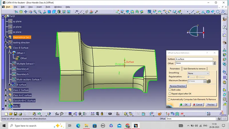
- For creation of B surface we offset class A surface inward by 3 mm which is the thickness of component.
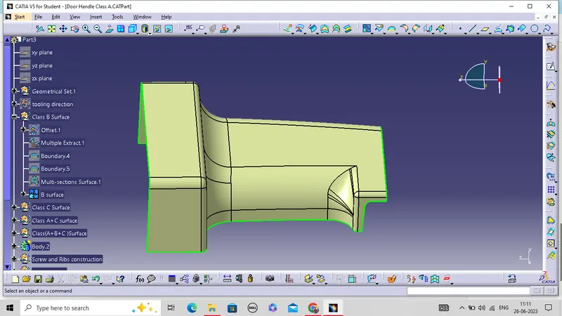
- There are some patches found after offseting.
- we have repaired patches through join ,extrude ,sweep ,multiple extract ,trim,multisection surface command according to need.
Create class C surface.
- Create the boundary of class a surface and by using sweep command create surface.
- Then join all the surfaces.
- Ensure that there is no any gap between the surfaces.
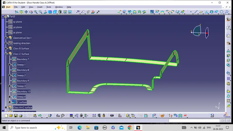
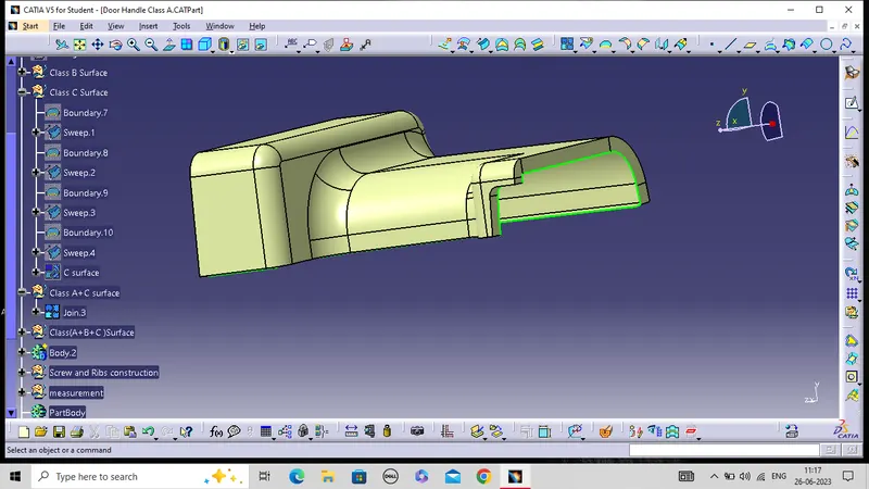
Joined A and C surface.
- Now join A and C surface together.
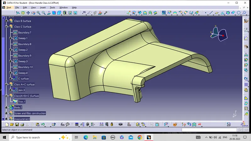
Final join all surfaces(A+B+C).
- Now trim the A+C surface with B surface.
Create solid component
- Now create a solid component using close surface command.
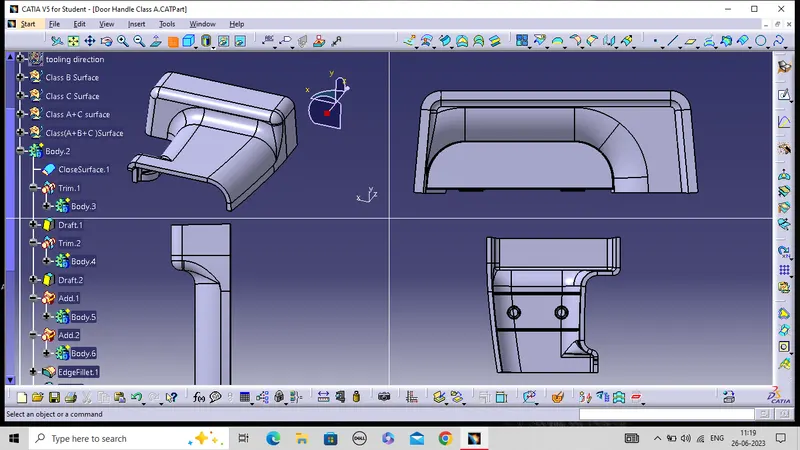
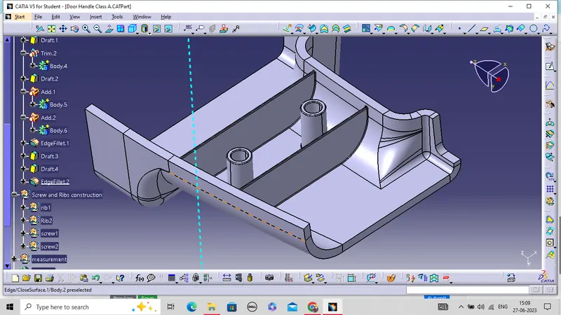
creation of Ribs
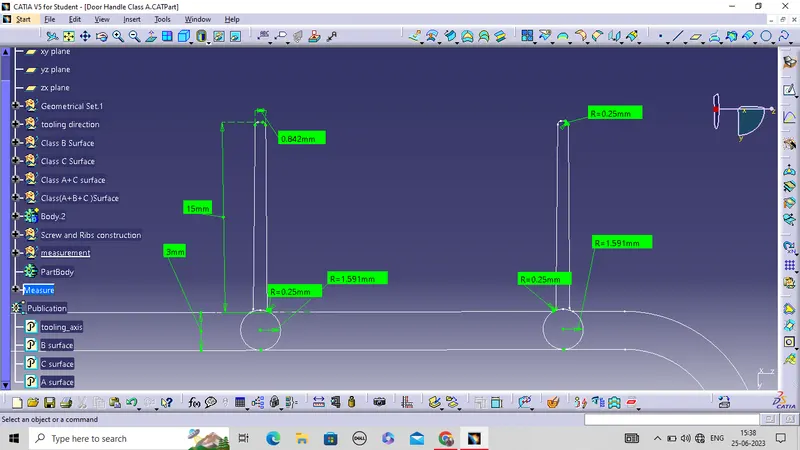
- For creation of proper rib there is some specific rule which should follow suring designing and creating the Rib.
- Component thickness(T)is taken as 3mm.
- Rib draft angle =0.5 degree.
- Rib fillet radius(r) can be = 0.5 >=r<=0.25.
- Rib thickness =0.4T;
- Rib tip thickness should be equal to 0.75 or more.distance between two rib should be minimum 3T.
General Guidelines for Bosses:
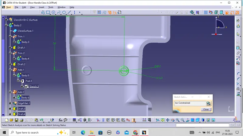
- Draft - 0.5 degrees on the walls of boss
- Thickness - Typically 40%* of the nominal wall at the base.
- Height to Diameter Ratio - 3:1
- Radii - 0.25mm maximum radii.
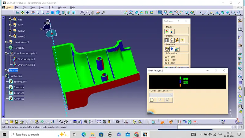
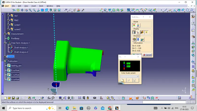
Draft Analysis:
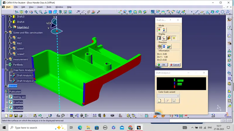
- First the class – A surface is checked before creating the Class –B&C surface and finally the solid body must be analysed. Both can be done by following the below procedures.
- By changing the view mode to custom view parameters – Material mode then the feature draft analysis is enabled.
- Then the compass was activated and placed with the tooling axis by dragging the red pointer and then locked it.
- Then, by selecting the quick analysis mode, the nominal value will be 3 degrees and checked for the component's draft angle and at angle 0.5 degree the ribs and screw boss will check.
- The green colour area shows that it satisfies the 3-degree draft angle.
Draft Analysis of A surface:
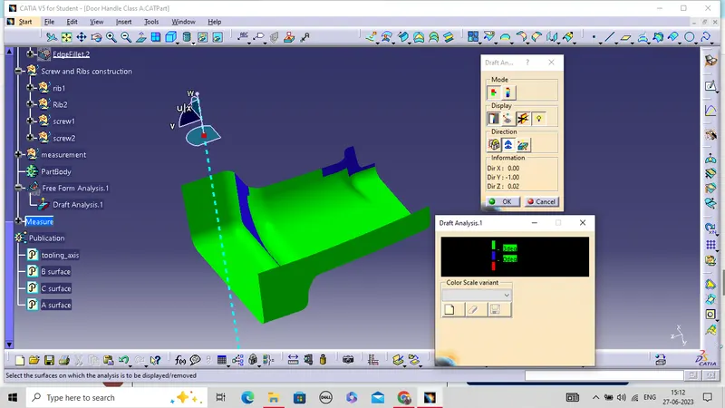
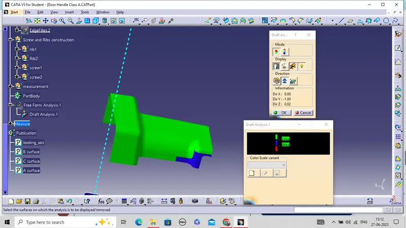
Draft Analysis of solid component ,Ribs and screw boss: