Menu


Modified on
Tensors, Stress, and 2D Meshing: A Primer for Beginners

Skill-Lync
A tensor is a mathematical object that describes a geometric relationship between vectors, scalars, and other tensors. They describe physical quantities with both magnitude and direction, such as velocity, force, and stress.
In this blog, let us look at why stress is a tensor, what a plain stress condition and how it is related to 2D meshing.
Before jumping to the scientific definition, studying tensors in relation to vectors would be helpful. Vectors are those quantities that are described using both magnitude and direction. E.g., Velocity
This means that a vector can be represented using a line, which lies in a particular plane, as shown below:

Thus a particular vector is unidirectional and lies in a plane in space. On the other hand, a tensor is a 3-dimensional quantity, meaning it has a volumetric distribution in multiple directions. To visualize it better, consider a color dropped in a glass of water, as represented below.

Image 2: Colour in water is distributed in all directions
The color is distributed in all directions, although not uniformly. A tensor also has a similar distribution in space. In simple terms, we can visualize this 3-dimensional distribution as a bundle of vectors related to each other by a definite relationship. This will allow us to understand the scientific definition of a tensor better.
Thus tensor is defined as an object that describes a relationship between sets of vectors in a vector space.
This brings us to the next question: why is stress a tensor?

Image 3: Conceptual representation of chemical bonds among particles of a material
Stress is the internal resistance offered by an object to its deformation. This is under the internal chemical bonds among the atoms/molecules of the object. So if a particular atom/molecule is deformed, the forces of attraction from the neighboring atoms/molecules will exert a resistive force, basically, the stress.
But since the neighboring atoms are distributed in a 3-dimensional space, the forces of resistance are also distributed in a 3-dimensional space in a definite relationship with one another. Since force is a vector, the bundle of all these force vectors creates a tensor.

Image 4: 3D Stress distribution within a part
The above image shows how stress is distributed in a 3-dimensional space in the object.
Because stress is a tensor, there are different ways to represent it. It can be expressed as matrix, a Mohr’s circle, von mises stress, or as normal and shear stresses separately.

Image 5: Normal stress, shear stress, and stress matrix
One approximation commonly used to simplify the representation and calculation of stress is called the plane stress condition.
In plane stress conditions, the normal and shear stresses directed perpendicular to a particular plane are assumed to be zero. This means, in the plane stress condition, the stress is assumed to be distributed in only one plane. E.g. the stress in the z-direction is assumed to be zero. This makes many of the terms in the stress matrix zero, which makes calculations easier.
To imagine the plain stress condition, just assume that an object comprises thin slices arranged on top of another. If we consider any one of the slices, the stress in that slice will be distributed in the plane of that slice only, as the thickness is very small compared to other two dimensions. The stress in the direction normal to the plane of the slice will be zero.
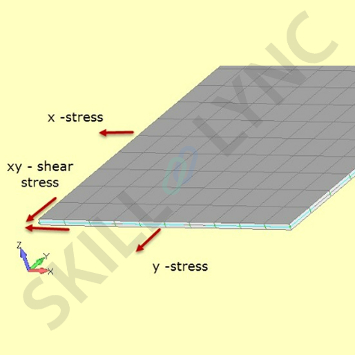
Image 6: Pictorial representation of plane stress conditions in XY plane
But what is the practical significance of plane stress conditions?
In FEA, to accurately analyze the state of a material, it's important to create a finite element mesh on the model. This process involves dividing the part into smaller elements and defining their behavior. 2D meshing involves creating a mesh in a single plane. Many thin components mesh using 2D elements like quad or tria. These 2D elements work on the principle of plain stress, under which stress normal to the plane of the elements is assumed to be zero.
This has 2 advantages:
Many of the terms in the stress matrix become zero, making calculations easier.
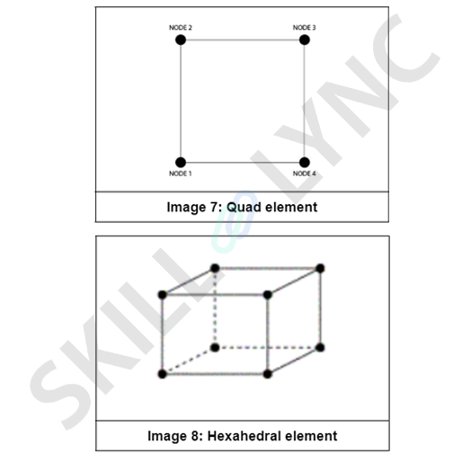
Two, the number of nodes under calculation is lesser than that in 3D meshing. In FEA, nodes are the points at which the edges of the elements intersect with each other. In layman's terms, they can be understood as the vertices of the elements. In 2D meshing, a linear quad element has 4 nodes. But the corresponding 3D element is the linear hexahedral or brick element, which has 8 nodes, as shown in the next image:
As a result, the calculation time is reduced, and we get faster results with reasonable accuracy.
So if you think about it, one of the basic engineering principles has become a foundational principle of FEA. In the image below, a sheet metal part, meshed using 2D elements is shown:
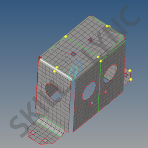
Image 9: the 2D meshing of a sheet metal part
This explains how tensors are related to plain stress conditions and 2D meshing. Understanding these concepts is crucial for accurately analyzing the behavior of models and ensuring their safety and stability.
Author

Navin Baskar
Author
Skill-Lync
Subscribe to Our Free Newsletter

Continue Reading
Related Blogs
Learn how to render a shock-tube-simulation and how to work on similar projects after enrolling into anyone of Skill-Lync's CAE courses.
09 May 2020
In this blog, read how to design the frontal BIW enclosure of a car (Bonnet) and learn how Skill-Lync Master's Program in Automotive Design using CATIA V5 will help you get employed as a design engineer.
09 May 2020
Tetrahedral is a four- nodded solid element that can be generated through the tria element by creating a volume and also through the existing volume of the geometry. These elements are used where the geometry has high thickness and complexity. The image attached below is a representation of a Tetra element. The Tetra element will have 4 triangular faces with four nodes joining them together
01 Aug 2022
A connector is a mechanism that specifies how an object (vertex, edge, or face) is connected to another object or the ground. By often simulating the desired behaviour without having to build the precise shape or specify contact circumstances, connectors make modeling simpler.
02 Aug 2022
One of the most crucial processes in carrying out an accurate simulation using FEA is meshing. A mesh is composed of elements that have nodes—coordinate positions in space that might change depending on the element type—that symbolise the geometry's shape.
03 Aug 2022
Author
Skill-Lync
Subscribe to Our Free Newsletter
Continue Reading
Related Blogs
Learn how to render a shock-tube-simulation and how to work on similar projects after enrolling into anyone of Skill-Lync's CAE courses.
09 May 2020
In this blog, read how to design the frontal BIW enclosure of a car (Bonnet) and learn how Skill-Lync Master's Program in Automotive Design using CATIA V5 will help you get employed as a design engineer.
09 May 2020
Tetrahedral is a four- nodded solid element that can be generated through the tria element by creating a volume and also through the existing volume of the geometry. These elements are used where the geometry has high thickness and complexity. The image attached below is a representation of a Tetra element. The Tetra element will have 4 triangular faces with four nodes joining them together
01 Aug 2022
A connector is a mechanism that specifies how an object (vertex, edge, or face) is connected to another object or the ground. By often simulating the desired behaviour without having to build the precise shape or specify contact circumstances, connectors make modeling simpler.
02 Aug 2022
One of the most crucial processes in carrying out an accurate simulation using FEA is meshing. A mesh is composed of elements that have nodes—coordinate positions in space that might change depending on the element type—that symbolise the geometry's shape.
03 Aug 2022
Related Courses