Wiring harness design in CATIA V5 - 3D modeling Week 2 Challenge
Download following connectors & Connector clip cad data from given link & define it as Electrical Connector using Electrical Part design Workbench. Define all the necessary properties to Connectors & Clip.
- Deutsch DT06 – 08SA ( https://www.te.com/usa-en/product-DT06-08SA.html)
- Tyco 174357-2 (https://www.te.com/usa-en/product-2-174357-2.html?source=header-match)
- Tyco 85229-1 – (https://www.te.com/usa-en/product-85229-1.html?q=85229&source=header)
Prepare a proper report with necessary images in the answer box provided
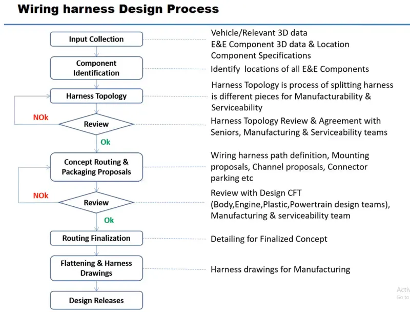
- DEFINIG ELECTRIC PARAMETER FLOW CHART
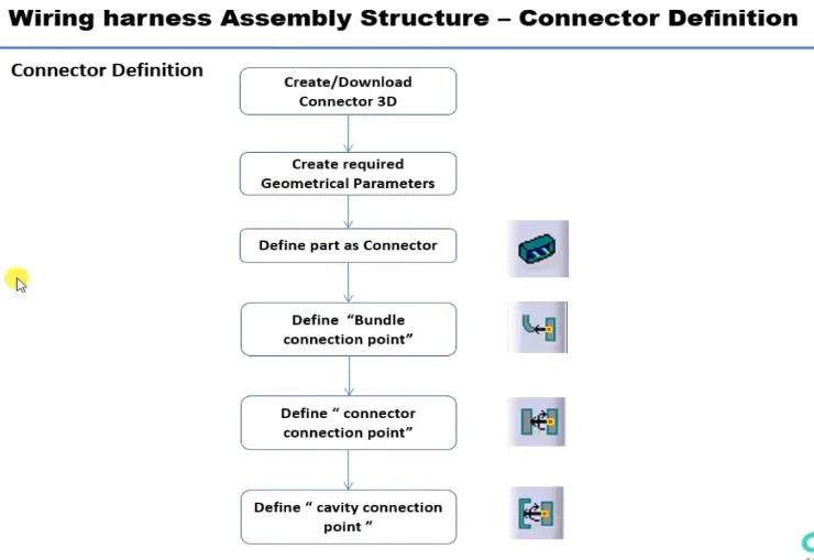
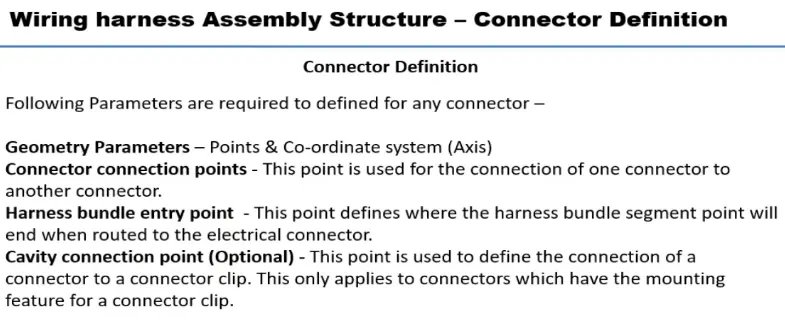
- CONNECTOR DEFINATIONS IN CATIA V5
1. Deutsch DT06 – 08SA
- Connector connection point
Create midpoint on the contact face which will be normal to wire bunddle insertion.
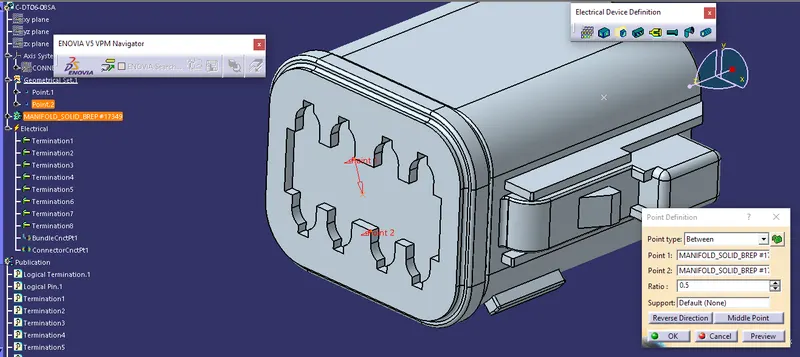
Defining Bundle entry point
Figure 3- Defining part as a Connector
Figure 4- Defining Bundle Connection Point
Figure 5- Defining Connector Connection Point
CONNECTOR 2- With Clip attachment- C-2-174357-2-E-3D –
Figure 1- Defining the Geometrical Parameter to the part
Figure 2- Defining Bundle entry point
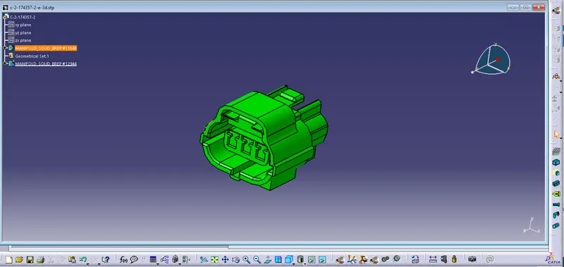
Figure 3- Defining the Geometrical Parameter for clip or cavity attachment
Figure 4- Defining part as a connector
Figure 5- Defining Bundle Connection Point
Figure 6- Defining Connector Connecting Point
Figure 7- Defining Cavity Connection Point
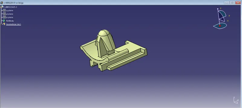
Tyco 85229-1 :
- Create midpoint
- create cavity connection point
- create cavity connection axis system and orientation should be same as in connector
- Switch to Electric part design and define part as Mounting Equipment
- Define cavity connection point
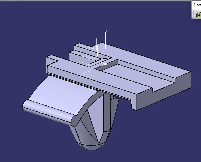
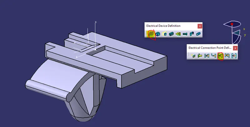
CLIP 2- C-0085229-01-A-3D-
Figure 1- Defining the Geometrical Parameters to the part
Figure 2- Defining part as mounting equipment (clip)
Figure 3- Defining Cavity
CLIP AND CONNECTOR ELECTRICAL ASSEMBLY-
CONCLUSION- Both the connectors and the clip were defined as an electrical connector and electrical mounting equipment respectively. All the necessary electrical and geometrical properties were given to the parts.