Project 1
Description:
Project 1 deals with the development of a forward energy-based fuel consumption model of a conventional vehicle.
The main goal of this project is to get familiar with the modeling process, writing scripts in Matlab, modeling in Simulink, analyzing data and generating plots.
In this project, a typical midsize car with a 1.9L engine and a 4-speed automatic transmission is considered. Data is taken from ADVISOR data base developed by NREL, USA. Transmission shift map and controller is taken from Matlab/Simulink example database.
The model developed has the capability to simulate the vehicle on different drive cycles like UDDS, HWFET, FTP, NEDC, etc.
“Project1_InitFile.m” is a Matlab script used to load all the variables required for running the Simulink model and for post-processing. The drive cycle selection is also done here. Before running the Simulink
vehicle model, run this initialization script.
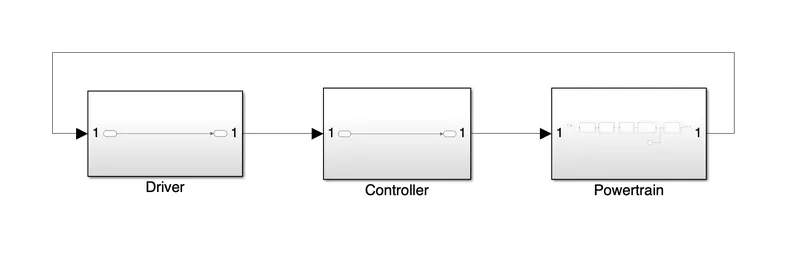
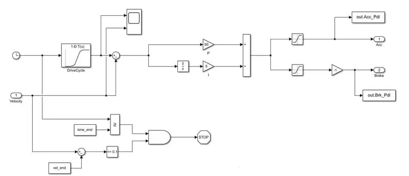
“Project1_VehicleModel.slx” is the Simulink model of the vehicle. It is modeled using a ‘Driver’ block, which is a basic PI controller that generates accelerator and brake pedal outputs to match the desired
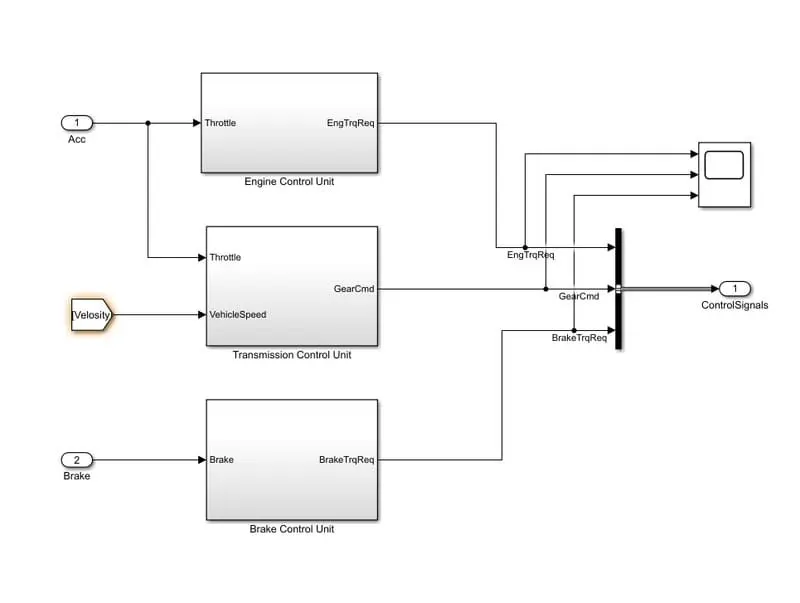
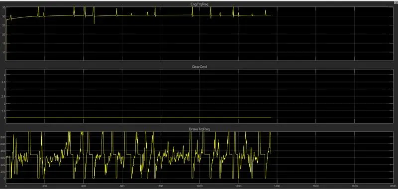
and actual vehicle speeds. The ‘Controller’ block is the brains of the vehicle, representing the electronic controls units. Based on the driver inputs, it generates desired engine torque, desired transmission gear
and desired brake torque. These inputs are fed to the ‘Powertrain’ block which represents the drivetrain of the vehicle. It consists of an ‘Engine’ connected to the ‘Automatic Transmission’ through a ‘Torque
Converter’. The output of the transmission is connected to the ’Differential’, which powers the ‘Wheels’, that provides the tractive force for vehicle acceleration. The longitudinal dynamics of the vehicle along with the road load is represented in the ‘Vehicle Dynamics’ block. The solver selected is ode3 with a fixed step size of 0.01 sec.
After running this Simulink model, data from the model will be loaded in the Matlab workspace.
“Project1_ProcessingFile.m” is the Matlab script used to analyze this data and to generate plots. This script needs to be executed after the Simulink model data has been loaded into the workspace. Here we
rename the variables loaded from the model (if desired), do some basic post-process calculations and generate results and plots.
Task:
The task of this project is to compute the fuel economy numbers for the given vehicle (kmpl) on the urban cycle (UDDS) and highway cycle (HWFET). Also, to analyze and understand the vehicle operating
points in terms of engine speed, torque, transmission speeds, pedal positions, gear, distance traveled, etc.
To do that, the following steps need to be followed:
1) Load the Project1 folder as the Current Folder in Matlab.
2) Run the “Project1_InitFile.m” Matlab script.
3) The provided vehicle Simulink model “Project1_VehicleModel.slx” is incomplete. The engine and vehicle dynamics block contents have been deleted. Build the Simulink blocks by referring to the course lecture and example block images provided. You can run the model and analyze the results using a ‘Scope’ for debugging.
4) Add additional ‘To Workspace’ blocks for transferring the desired Simulink vehicle data into the Matlab workspace.
5) Modify the “Project1_ProcessingFile.m” as per the desired plots and required calculations.
6) Write a project report that contains the following:
a. Tabulate the fuel economy numbers (kmpl) for UDDS and HWFET cycle. This forms the baseline numbers for comparing with the future hybrid version.
b. Plot the time trace for engine, transmission input, transmission output and wheel speed on one plot.
c. Plot engine torque, engine power, fuel rate and fuel consumption using subplots.
d. Plot accelerator and brake pedal, gear command, vehicle desired and actual speed, vehicle distance using subplots.
e. Plot the engine operating points on the engine fuel map.
f. Write down appropriate brief comments on each of these plots, describing the vehicle behavior throughout the drive cycle.
g. Generate the plots for both drive cycles
ANSWER :
Project1 InitFile.m:-
“Project1_InitFile.m” is a Matlab script used to load all the variables required for running the Simulink model and for post-processing. The drive cycle selection is also done here. Before running the Simulink vehicle model, this initialization script is run.
Driver:
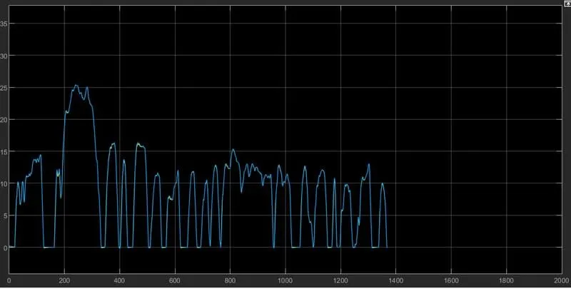
Controller:
Power Train:
Engine:
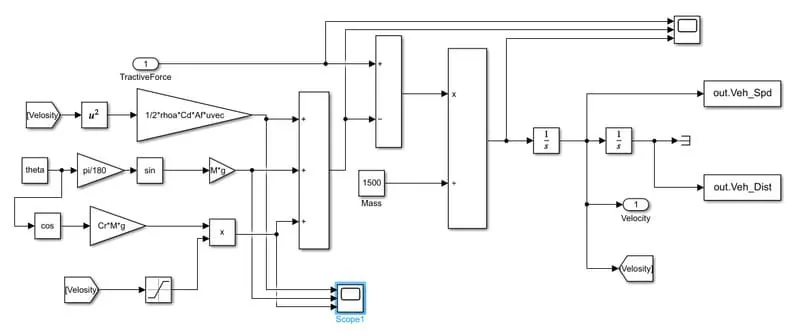
Now, the Vehicle dynamics block is developed using the equations
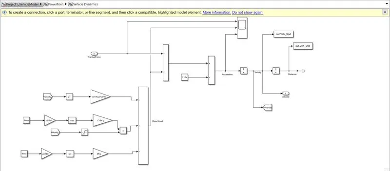
Equations for aerodynamic drag, rolling resistance, and gradient are created and summed up to get the road load
Road load is subtracted from the tractive force to get the force
This force is then divided by the mass to get the acceleration component
Integrator is used to integrate the acceleration and get the velocity component
Road load and velocity are multiplied to get the power required for the vehicle
Power is then multiplied by the total time to get the energy required
All the blocks of velocity, acceleration, road load, the power required, and energy required are attached to the 'scope' block to
see the output variations with respect to the time
Vehicle Dynamics:
Transmission:
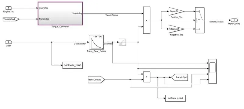
In these model we take engine torque, gear selector from controllerb for transmission of gear ratio. The ratio is multiply by transmission input torque and then the transmission efficiency positive torque and negative torque gives transmission input speed. In this case torque converter connects the engine to transmission it is part of transmission. In it basically engine dynamics and that is decoupled.
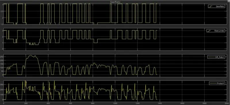
Graph created from Scope in Driver Model:- 1] Transmission in speed 2] Gear ratio 3] Differential Ratio
Differential:
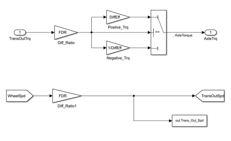
In this taking input is the transmission output then its going to the differential ratio multiplied the output and input torque then meet axle torque. The axle torque is a lower than the transmission torque and differential ratio.
Wheels:
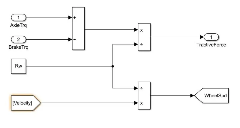
In this model we take the axle torque from differentail and brake torque from controller. it is substracts and multiplied rolling radius and velocity then we meet the tractive force from axle and brake torque. and the wheelspeed is meet using velocity.
5] Vehicle Dynamics:-
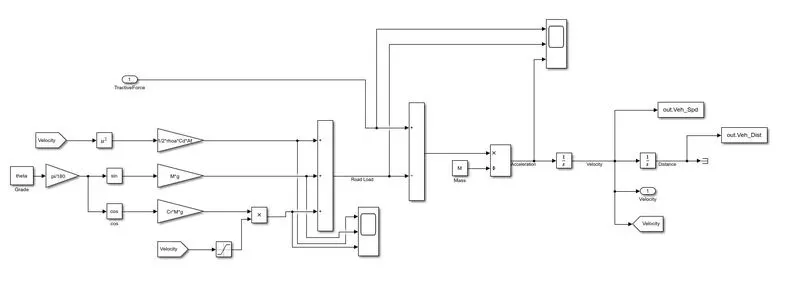
In this takes tractive force and road load. It is dictates vehicle speed based on tractive force and road load.
where,
p = air density [kg/m^3]
A = Frontal area [m^2]
Cd = drag Coefficiend
Vveh = velocity of vehicle [m/s^2]
Vwind = velocity of wind [m/s^2]
Cr = rolling resistance coefficient
M = mass in [Kg]
g = gravity.
Then we calculate and integrate then we meet acceleration of vehicle and velocity of vehicle it mean vehicle distance and vehicle speed.
Graph created from Scope in Driver Model:- 1] Road load 2] Acceleration 3] Tractive force
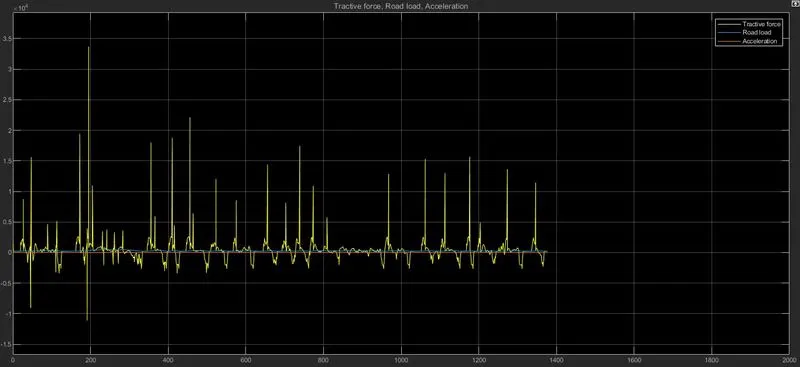
Graph created from Scope in Driver Model:- 1] Road load
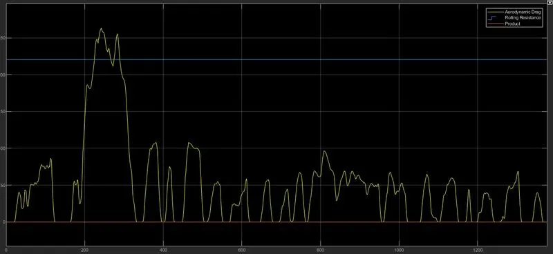
Now,
We compute the Fuel economy numbers using UDDS and HWFET cycle:-
1] UDDS Drive cycle
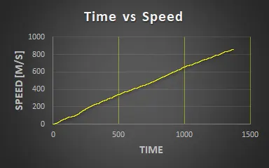
1] Time VS Speed:- In this the speed is increasing continuously.
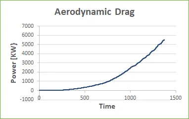
2] Aerodyanamic drag:- Drag as increase when the power increase.
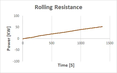
3] Rolling Resistance:- Its also increase when power is increase wrt time.
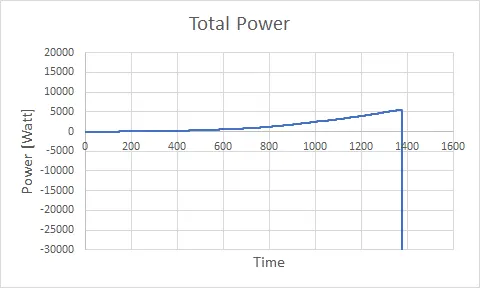
4] Total power = aerodynamic drag+rolling resistance+inertial resistance
Conclusion:-
Total Power is increase slowly as increasing rolling resistance, aerodynamic drag and inertial resistance.
2] HWFET Drive Cycle:-
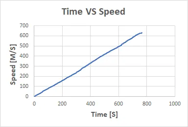
1] Time VS Speed:- Speed is continuosly increase wrt time.
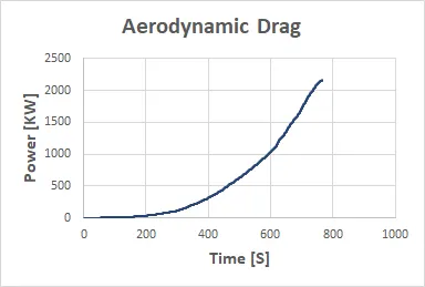
2] Aerodynamic Drag:- Drag as increase when the power increase.
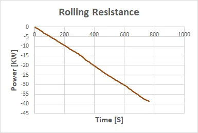
3] Rolling Resistance:- In this resistance is decrease wrt time.
4] Total Power:- aerodynamic drag+rolling resistance+inertial resistance
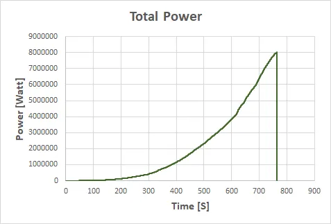
The power required for propelling an EV is that which overcomes the friction forces due to weightlessness, aerodynamics, and rolling.
Conclusion:-
Total Power is increase slowly as increasing aerodynamic drag and inertial resistance. but in this drive cycle bad impact occurs due to decreasing rolling resistance.
Result:-
As comparing both cycles we used to UDDS drive cycle. Its best for asses of fuel consumption and Pollutants emission of vehicle in a normalised way.
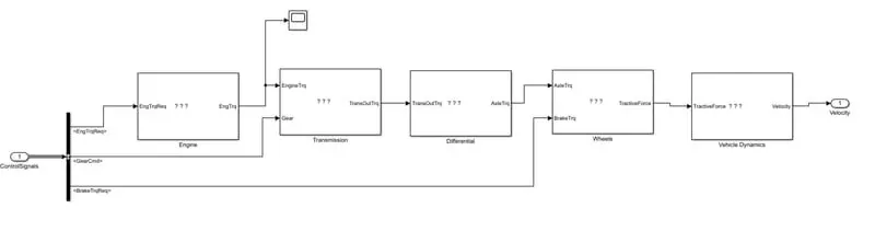
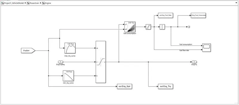
Firstly I have run the “Project1_InitFile.m” to load all the variables required for running the Simulink model and for post-processing. The drive cycle selection is also done here. Before running the Simulink vehicle model, run this initialization script. After that,I have opened given vehicle model file “Project1_VehicleModel.slx” in the Simulink and completed engine and vehicle dynamic block.The engine and vehicle dynamic block is shown in following images.
Drive Cycle HWFET
The Highway Fuel Economy Driving Schedule (HWFET) represents highway driving conditions under 60 mph.
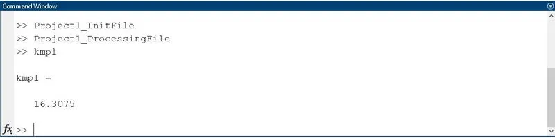
Fuel economy is 16.5010 [kmpl]
As per the fuel economy value for both cycles, the HWFET drive cycle has a higher economy than the UDDS drive cycle.
Results :-
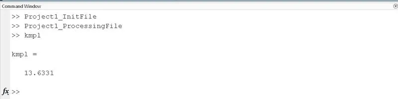
* The fuel economy numbers (kmpl) for UDDS cycle.
* The fuel economy numbers (kmpl) for HWFET cycle.
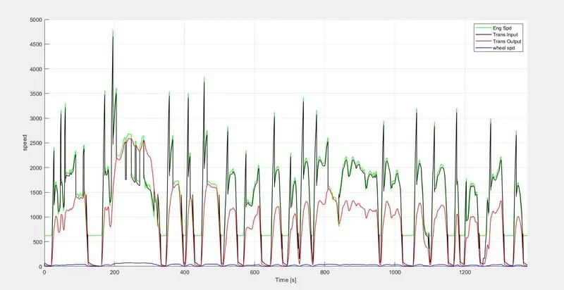
* Plot the time trace for engine, transmission input, transmission output and wheel speed on one plot.
# Plot for UDDS drive cycle :-
More power is generated in this drive cycle with more torque. A drastic change in the movement of the torque can be seen. There is less fluctuation in engine speed. Engine fuel consumption increases with time.
# Plot for HWFET drive cycle :-
Drive Cycle HWFET
The brake pedal seems to be steady in the overall ride. Mostly the vehicle is at maximum gear and there is less movement in the accelerator pedal, only when there is a slight movement in the brake pedal. Less fluctuation is seen in the speed part for this drive cycle.
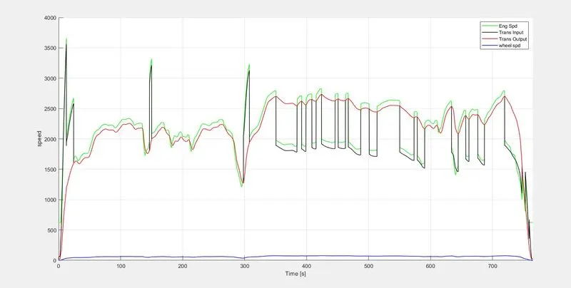
In above images time trace plot for engine speed ,Transmission input and output speed,wheel speed are shown for UDDS and HWFET drive cycle respectively.This data we get from engine ,transmission and wheel blocks of powertarin. from respective blocks this data is transfered to workspace .As shown in above image ,speed get reduces from engine to wheel.
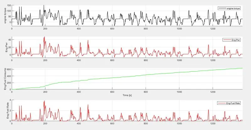
* Plot engine torque, engine power, fuel rate and fuel consumption using subplots.
# Plot for UDDS drive cycle :-
In the below plot, it can be seen that with an increase in gear, the accelerator pedal increases and there is no movement with the brake pedal. The speed increases with the moment of transmission input and output. Speed seems to be zero when there is movement in the brake pedal.
The vehicle reaches max gear only once in this cycle. The maximum time it is in 1st or 2nd gear.
# Plot for HWFET drive cycle :-
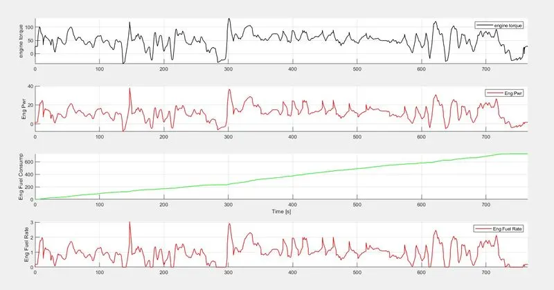
The above plot shows the variation in engine torque,engine power ,fuel rate and fuel consumption.As the requirement of engine torque and power increases,the fuel rate also get increased.
More power is generated in this drive cycle with more torque. A drastic change in the movement of the torque can be seen. There is less fluctuation in engine speed. Engine fuel consumption increases with time.
* Plot the engine operating points on the engine fuel map. :-
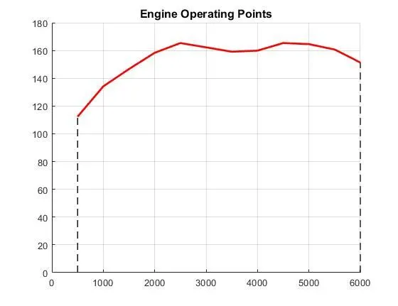
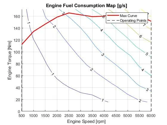
In this the as decrease torque speed is increase.
The engine operating points are speed and torque points obtained from simulation results which is plotted on the speed and torque input map showing the area where the engine operates with respect to the data provided.
For a given power requirement, the number of gears in a transmision provide the number of operating points for the powertrain in terms of torque and speed.
CONCLUSION
- Hence, the forward energy-based fuel consumption model of a conventional vehicle has been successfully Simulated using MATLAB and Simulink.
- Analyses and understands vehicle operating points based on engine speed, torque, transmission speed, pedal positions, gear, and distance travelled.
- Post process calculations were performed and the required graphs were successfully plotted.
- Successfully calculated vehicle fuel efficiency numbers (kmpl) for the given city cycle (UDDS) and highway cycle (HWFET)
- Both the plots are generated UDDS and HWFET