Week 9 - Project - Master Section Development
AIM:
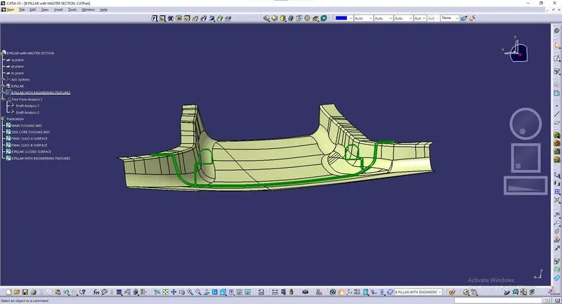
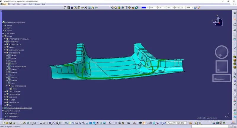
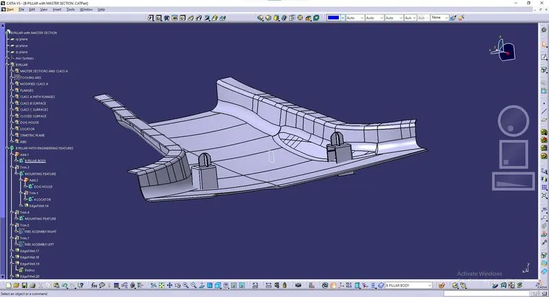
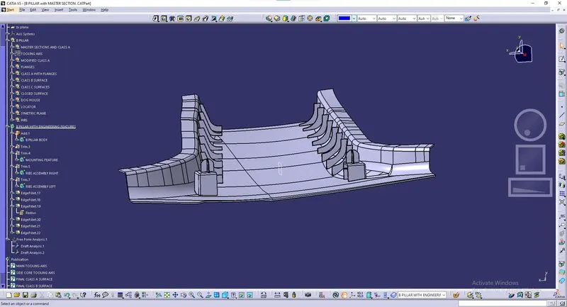
To create a solid body of B pillar cover including ribs and locators using CATIA v5 tool using given A-class surface and master section and adding thickness.
INTRODUCTION :
B-Pillar
The B-pillar is the central pillar of the car. This pillar is actually a sheet metal part that is welded in the BIW of the car. The B-pillar trim is attached to the B-pillar and improves the aesthetic look of the car. Mostly the trims are manufactured by the injection molding process. The design of the B-pillar is carefully done to make the part manufacturable and usable in the interior. While manufacturing a part through injection molding a lot of defects can occur on the plastic part which will destroy the look of the panel. The design has to make in such a way that all the errors can be rectified.
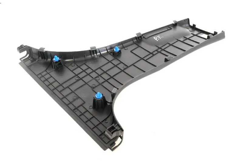
OVERVIEW DESIGN LIFE CYCLE AUTOMOTIVE INDUSTRY
The Stages of Design Life Cycle are
Concept Sketches:
Concept sketches are rough idea of free hand sketch obtained through styling team and will be used to prepare the Model. It is usually done through pen and paper and through the painting software. This is will be used to generate the concept for preparing the model by incorporating various styles and information obtained through the stakeholders
Class A Creation:
After finalizing the concept the sketches are usually worked in software’s such as Autodesk Alias to create Class A Surface
Clay Modeling :
The Class A Surface is concurrently worked by clay modelers to brainstorm and benchmark the styling of the product and later the Concept is validated by bringing up a rough clay model and then it is passed on to the Design team for the preparation of New Product Design (NPD) CAD.
NPD CAD :
This where the development of surfaces to parts in CAD kick off and Design engineers involvement is vital in this stage.
The Designers will work on the Input Class A surfaces which are validated from the Feasibility team
The procedure followed in creation of the plastic New Product Design are
- Tooling Axis
- B Surface Creation
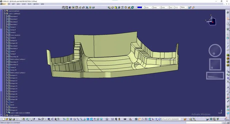
- C Surface Creation
- Closed Body Creation
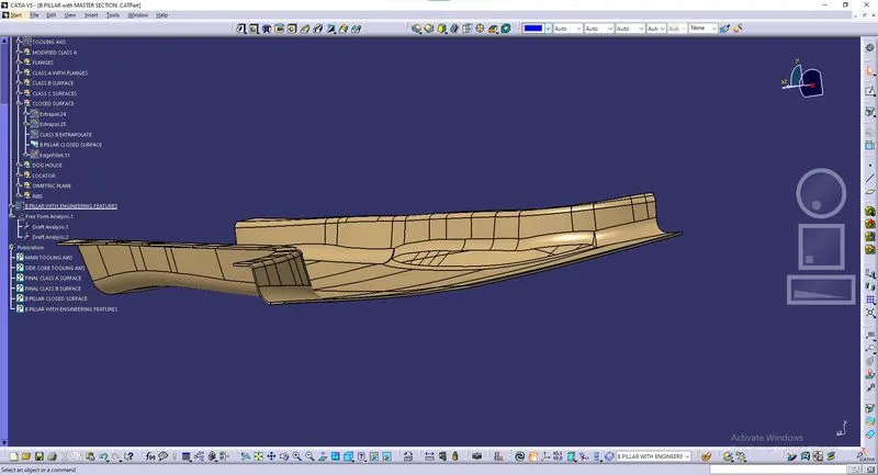
- Draft Analysis
TOOLING AXIS
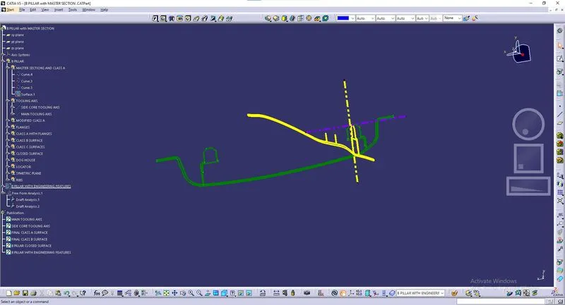
Class A surface of a component refers to the aesthetic surface which is visible to the naked eye when we observe a body(such as a car). In general, they are high-quality surfaces that have some fine finishing and aesthetic look to them. As plastic components are injection molded, we need a tooling axis for the core and the cavity. The tooling axis/direction is the direction in which the molds (core and cavity) move apart/together which means it serves as the reference to design your data up against. One more point to be noted here is that the draft is always provided along the tooling axis so that it can be easy when the component/mold is parted.
PROCEDURE:
CONCLUSION
- Class A, B, and C surfaces were created as per the automotive standards using CATIA v5software.
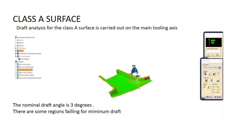
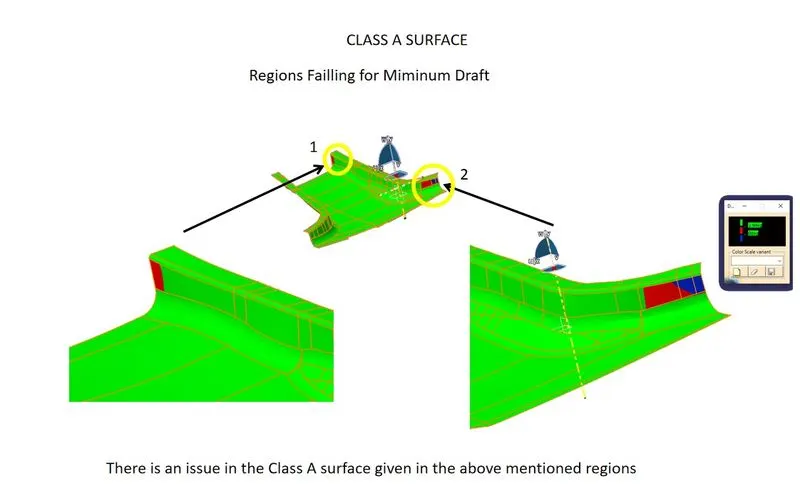
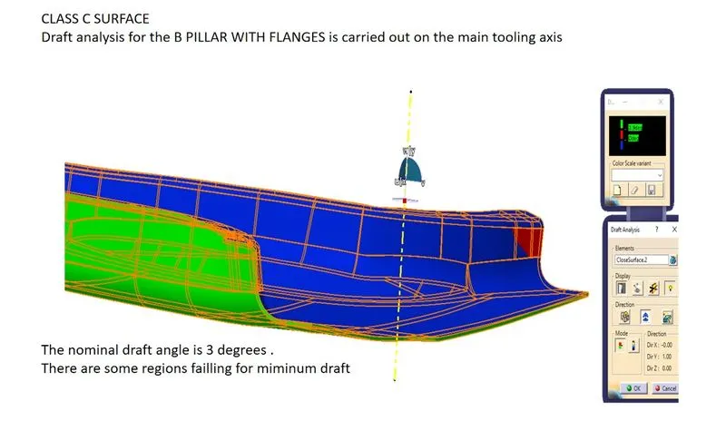
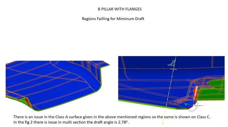
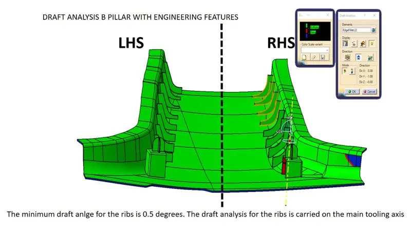
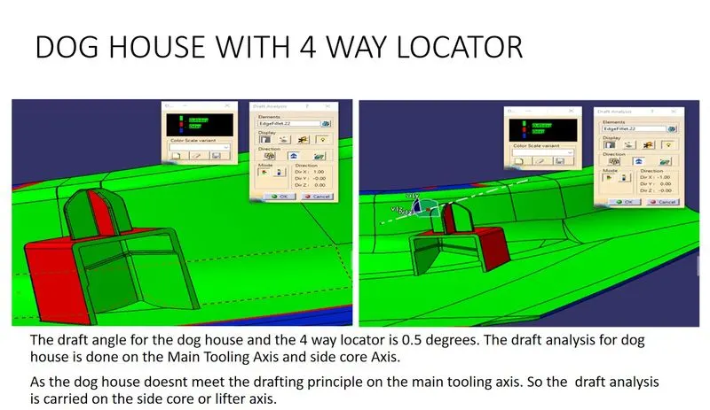
- Draft analysis was performed for the built model and it could be seen that the draft was under the permissible limit for the manufacturing of the component.
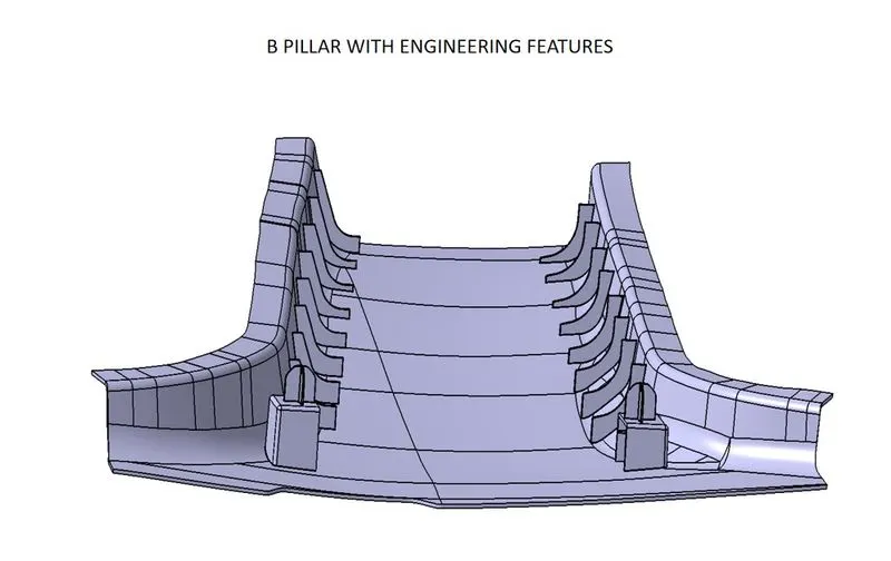
- B side features were created for the component as per the design rules.