Week 9-Creation of 1D Connectors Challenge
AIM:- To create a mesh and connectors for the given Chassis Frame as mentioned for each truss and rail .
OBJECTIVE :-
- To create a quality criteria file and mesh the trusses with mixed mesh with target size to be 5.
- Create connector and Attach the various parts of the given chassis frame
- At Right Rail 2 & Front truss 1 connect using Seam Quad (angled+capped+L).
- At Left Rail 2 & Front truss 1 connect using Quad elements.
- At Front truss 2, Front truss 1 & Right Rail 1 connect using Spot weld with 2 Layers and 5 mm Diameter.
- At Front truss 2, Front truss 1 & Left Rail 1 connect using Hexa (Adhesive).
- At Rear truss 2 & Right Rail 2 connect using Bolt Connector.
- At Rear truss 2 & Left Rail 2 connect using Bolt Connector.
- At Right Rail 1 & Right Rail 2 connect using Spot weld with Rigid Elements.
- At Left Rail 1 & Left Rail 2 connect using Spot weld with Spring Elements.
- At remaining Rail ,truss and reinforcement plate connect using other type of connector.
PROCEDURE:-
* The quailty criteria file is been updated as per as the given task, and model is been imported as shown in fig 1.1 .
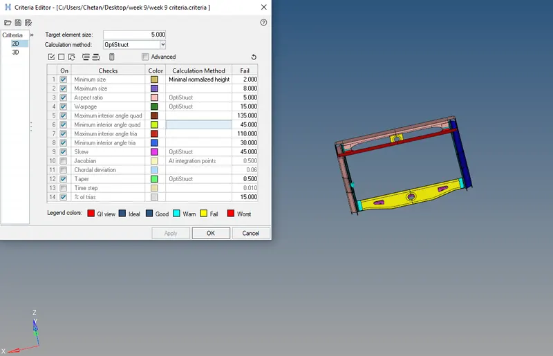
fig 1.1
* The frame components are selected and mesh by automesh using element size to be 5 units as shown in fig 1.2.
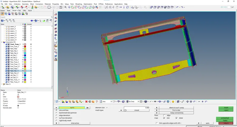
fig 1.2
*By using the connector tool, the Seam option is used at Right Rail 2 & Front truss 1 connect using Seam Quad (angled+capped+L) as shown in fig 1.3.
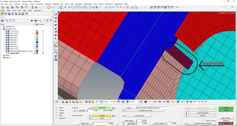
fig 1.3
*By using the connector tool, the Seam option is used at Left Rail 2 & Front truss 1 connect using Quad elements as shown in fig 1.4.
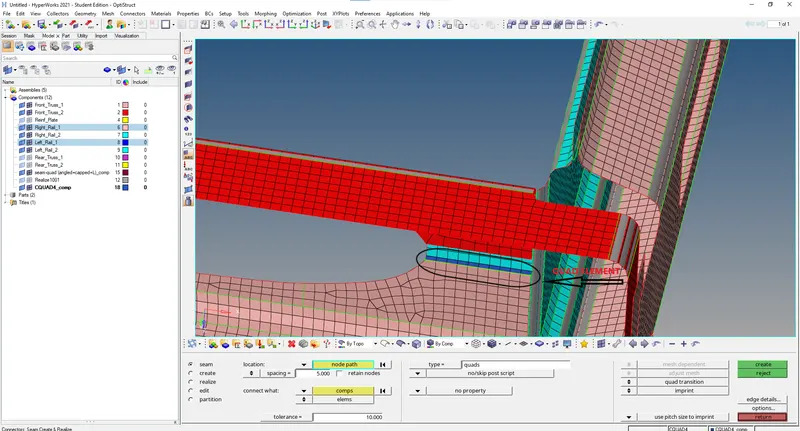
fig 1.4
*By using the connector tool, the Spot option is used at Front truss 2, Front truss 1 & Right Rail 1 connect using Spot weld with 2 Layers and 5 mm Diameter as shown in fig 1.5.
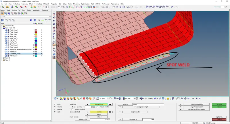
fig 1.5
*By using the connector tool, the Seam option is used at Front truss 2, Front truss 1 & Left Rail 1 connect using Hexa (Adhesive) as shown in fig 1.6.
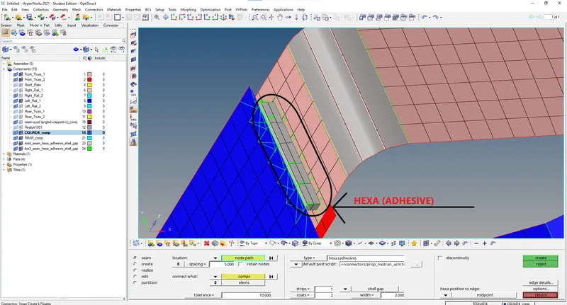
fig 1.6
*By using the connector tool, the Bolt option is used at Rear truss 2 & Right Rail 2 connect using Bolt Connector. The same is repeated at Rear truss 2 & Left Rail 2 connect using Bolt Connector as shown in fig 1.7.
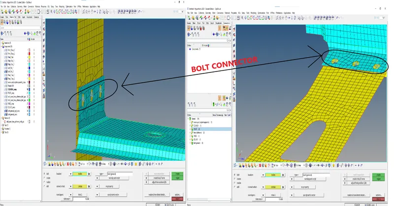
fig 1.7
*By using the connector tool, the Spot option is used at Right Rail 1 & Right Rail 2 connect using Spot weld with Rigid Elements as shown in fig 1.8.
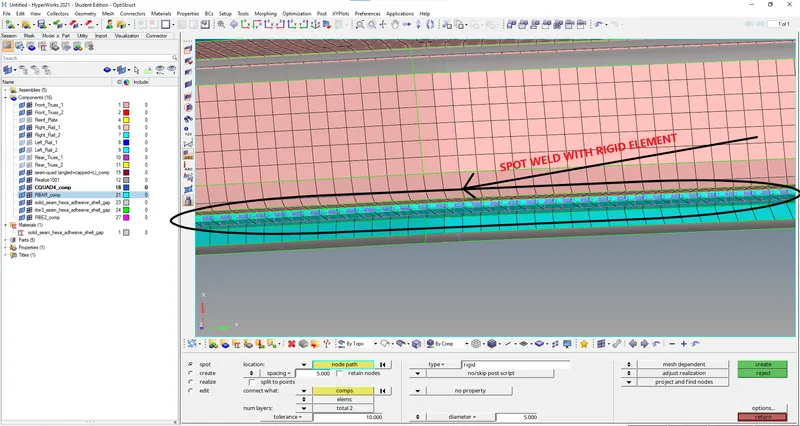
fig 1.8
*By using the connector tool, the Spot option is used at Left Rail 1 & Left Rail 2 connect using Spot weld with Spring Elements as shown in fig 1.9.
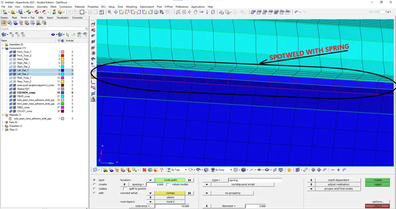
fig 1.9
*By using the connector tool, the Seam option is used at remaining Rail ,truss and reinforcement plate connect using other type of connector as shown in fig 1.10.
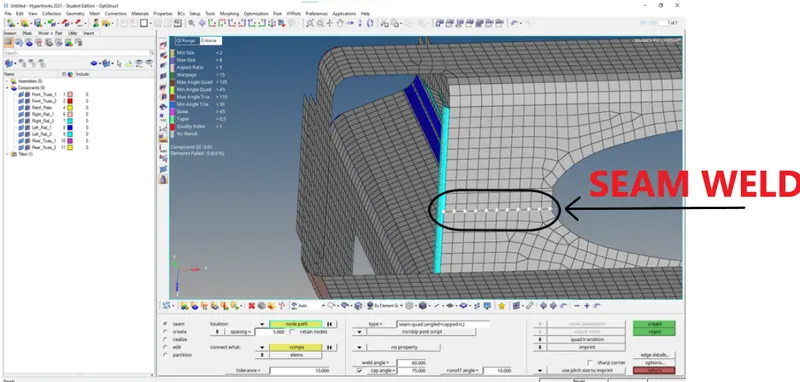
fig 1.10
RESULT:- The chassis frame rails and trusses are connected using the mentioned type and all the components are connected .